
Acer Aspire 5810T, Aspire 5810TZ Notebook Series Start Guide
Page 7
7 Closed front view English # Icon 1 2 Item Battery 5-in AC mode. Note: Push to remove/install the card. Only one card can operate at any given time. Accepts Secure Digital (SD), MultiMediaCard (MMC), Memory Stick (MS), Memory Stick PRO (MS PRO), xDPicture Card (xD). Rear view # Icon 1 Item Battery bay Description Houses the computer's battery pack. Charging: The light shows amber when the battery is charging. 2. Fully charged: The light shows blue when in -1 card reader Description Indicates the computer's battery status. 1.
7 Closed front view English # Icon 1 2 Item Battery 5-in AC mode. Note: Push to remove/install the card. Only one card can operate at any given time. Accepts Secure Digital (SD), MultiMediaCard (MMC), Memory Stick (MS), Memory Stick PRO (MS PRO), xDPicture Card (xD). Rear view # Icon 1 Item Battery bay Description Houses the computer's battery pack. Charging: The light shows amber when the battery is charging. 2. Fully charged: The light shows blue when in -1 card reader Description Indicates the computer's battery status. 1.

Acer Aspire 5810T, Aspire 5810TZ Notebook Series Start Guide
Page 10
Note: Do not cover or obstruct the opening of the fan. 6 Battery release latch Releases the battery for removal. 10 Base view English # Icon Item 1 Battery bay Description Houses the computer's battery pack. 2 Battery lock Locks the battery in position. 3 Memory compartment Houses the computer's main memory. 4 Hard disk bay Houses the computer's hard disk (secured with screws). 5 Ventilation slots and Enable the computer to stay cool, even cooling fan after prolonged use.
Note: Do not cover or obstruct the opening of the fan. 6 Battery release latch Releases the battery for removal. 10 Base view English # Icon Item 1 Battery bay Description Houses the computer's battery pack. 2 Battery lock Locks the battery in position. 3 Memory compartment Houses the computer's main memory. 4 Hard disk bay Houses the computer's hard disk (secured with screws). 5 Ventilation slots and Enable the computer to stay cool, even cooling fan after prolonged use.
Acer Aspire 5810T, Aspire 5810TZ Notebook Series Start Guide
Page 12
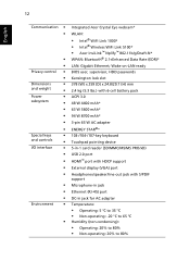
... ready BIOS user, supervisor, HDD passwords Kensington lock slot 378 (W) x 259 (D) x 24.8/29.7 (H) mm 2.4 kg (5.3 lbs.) with 6-cell battery pack ACPI 3.0 48 W 4400 mAh* 63 W 5600 mAh* 94 W 8700 mAh* 3-pin 65 W AC adapter ENERGY STAR®* 103-/104-/...8226; • • • • • • • Environment • • Integrated Acer Crystal Eye webcam* WLAN: • Intel® WiFi Link 1000* • Intel® Wireless WiFi Link 5100* • Acer InviLink™ Nplify™ 802.11b/g/Draft-N* WPAN: Bluetooth® 2.1+Enhanced Data Rate (EDR)* LAN: Gigabit...
... ready BIOS user, supervisor, HDD passwords Kensington lock slot 378 (W) x 259 (D) x 24.8/29.7 (H) mm 2.4 kg (5.3 lbs.) with 6-cell battery pack ACPI 3.0 48 W 4400 mAh* 63 W 5600 mAh* 94 W 8700 mAh* 3-pin 65 W AC adapter ENERGY STAR®* 103-/104-/...8226; • • • • • • • Environment • • Integrated Acer Crystal Eye webcam* WLAN: • Intel® WiFi Link 1000* • Intel® Wireless WiFi Link 5100* • Acer InviLink™ Nplify™ 802.11b/g/Draft-N* WPAN: Bluetooth® 2.1+Enhanced Data Rate (EDR)* LAN: Gigabit...
Aspire 5810TZ Service Guide
Page 7
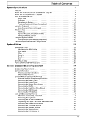
Table of Contents System Specifications 1 Features 1 Aspire 5810T/5810TZ/5410T System Block Diagram 3 Aspire 5810TG System Block Diagram 4 Your Acer Notebook tour 5 Right View 8 Indicators 11 Easy-Launch Buttons 1 Touchpad basics (with two-click buttons 11 Using the Keyboard ... General Information 40 Pre-disassembly Instructions 40 Disassembly Process 40 External Module Disassembly Process 41 External Modules Disassembly Flowchart 41 Removing the Battery Pack 42 Removing the Lower Cover 43 Removing the Optical Drive Module 44 Removing the DIMM 45 Removing the Hard Disk Drive...
Table of Contents System Specifications 1 Features 1 Aspire 5810T/5810TZ/5410T System Block Diagram 3 Aspire 5810TG System Block Diagram 4 Your Acer Notebook tour 5 Right View 8 Indicators 11 Easy-Launch Buttons 1 Touchpad basics (with two-click buttons 11 Using the Keyboard ... General Information 40 Pre-disassembly Instructions 40 Disassembly Process 40 External Module Disassembly Process 41 External Modules Disassembly Flowchart 41 Removing the Battery Pack 42 Removing the Lower Cover 43 Removing the Optical Drive Module 44 Removing the DIMM 45 Removing the Hard Disk Drive...

Aspire 5810TZ Service Guide
Page 14
Charging: The light shows amber when the battery is charging. 2. Note: Push to remove/install the card. Fully charged: The light shows blue when in AC mode. 2 5-in-1 card reader Accepts Secure Digital (SD), MultiMediaCard (MMC), Memory Stick (MS), Memory Stick PRO (MS PRO), xD-Picture Card (xD). Closed Front View # Icon Item Description 1 Battery Indicates the computer's battery status. 1. Only one card can operate at any given time. 6 Chapter 1
Charging: The light shows amber when the battery is charging. 2. Note: Push to remove/install the card. Fully charged: The light shows blue when in AC mode. 2 5-in-1 card reader Accepts Secure Digital (SD), MultiMediaCard (MMC), Memory Stick (MS), Memory Stick PRO (MS PRO), xD-Picture Card (xD). Closed Front View # Icon Item Description 1 Battery Indicates the computer's battery status. 1. Only one card can operate at any given time. 6 Chapter 1

Aspire 5810TZ Service Guide
Page 17
Rear View # Icon Item Description 1 Battery bay Houses the computer's battery pack. Chapter 1 9
Rear View # Icon Item Description 1 Battery bay Houses the computer's battery pack. Chapter 1 9

Aspire 5810TZ Service Guide
Page 18
latch 10 Chapter 1 Note: Do not cover or obstruct the opening of the fan. 6 Battery release Releases the battery for removal. compartment 4 Hard disk bay Houses the computer's hard disk (secured with screws). 5 Ventilation slots Enable the computer to stay cool, even after prolonged and cooling fan use. Bottom View Icon Item Description 1 Battery bay Houses the computer's battery pack. 2 Battery lock Locks the battery in position. 3 Memory Houses the computer's main memory.
latch 10 Chapter 1 Note: Do not cover or obstruct the opening of the fan. 6 Battery release Releases the battery for removal. compartment 4 Hard disk bay Houses the computer's hard disk (secured with screws). 5 Ventilation slots Enable the computer to stay cool, even after prolonged and cooling fan use. Bottom View Icon Item Description 1 Battery bay Houses the computer's battery pack. 2 Battery lock Locks the battery in position. 3 Memory Houses the computer's main memory.
Aspire 5810TZ Service Guide
Page 19
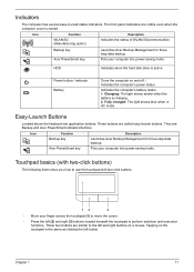
.... Icon Function Description WLAN/3G (Manufacturing option) Indicates the status of WLAN/3Gcommunication. Power button / indicator Battery Turns the computer on the touchpad is closed. Easy-Launch Buttons Located above the keyboard are : Backup and Acer PowerSmart indicators/buttons. Fully charged: The light shows blue when in AC mode. They are application...
.... Icon Function Description WLAN/3G (Manufacturing option) Indicates the status of WLAN/3Gcommunication. Power button / indicator Battery Turns the computer on the touchpad is closed. Easy-Launch Buttons Located above the keyboard are : Backup and Acer PowerSmart indicators/buttons. Fully charged: The light shows blue when in AC mode. They are application...
Aspire 5810TZ Service Guide
Page 31
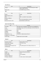
...Codec Controller NB Chipset Intel CS GS45NB + SB Chipset Intel CS AM82801IUX AMD M92LP (Aspire 5810TG) /UMA (Aspire 5810T/5810TZ/5410T) Intel ICH9M N/A N/A BCM2046 WLAN 802.11ABGN SHIRLEYPEAK1*2 Realtek Audio Codec ALC269X ...Keyboard Item Keyboard controller Total number of keypads Windows logo key Internal & external keyboard work simultaneously Specification Winbond WP CE 773LA 103-/104-/107-key Yes Plug USB keyboard to the USB port directly: Yes Battery Item Vendor Battery...
...Codec Controller NB Chipset Intel CS GS45NB + SB Chipset Intel CS AM82801IUX AMD M92LP (Aspire 5810TG) /UMA (Aspire 5810T/5810TZ/5410T) Intel ICH9M N/A N/A BCM2046 WLAN 802.11ABGN SHIRLEYPEAK1*2 Realtek Audio Codec ALC269X ...Keyboard Item Keyboard controller Total number of keypads Windows logo key Internal & external keyboard work simultaneously Specification Winbond WP CE 773LA 103-/104-/107-key Yes Plug USB keyboard to the USB port directly: Yes Battery Item Vendor Battery...

Aspire 5810TZ Service Guide
Page 43
... "Steps for the following conditions: • New versions of system programs • New features or options • Restore a BIOS when it becomes corrupted. If the battery pack does not contain enough power to any USB port. 5. Copy the "XXXXXXX.FD" file to the system. 6. Power on page 117) before you may...
... "Steps for the following conditions: • New versions of system programs • New features or options • Restore a BIOS when it becomes corrupted. If the battery pack does not contain enough power to any USB port. 5. Copy the "XXXXXXX.FD" file to the system. 6. Power on page 117) before you may...
Aspire 5810TZ Service Guide
Page 49
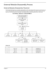
... below gives you a graphic representation on the components that order. EXTERNAL MODULE DISASSEMBLY TURN OFF POWER AND PERIPHERALS UNPLUG POWER CABLES REMOVE BATTERY PACK Hx4 Captive Screwx4 LOWER COVER RTC BATTERY Screw List A C D H SSD MODULE Ax1 ODD MODULE DIMM MODULES HDD MODULE OPTICAL DISK DRIVE Dx1 OPTICAL LOCKER BRACKET Cx2 HARD DISK...
... below gives you a graphic representation on the components that order. EXTERNAL MODULE DISASSEMBLY TURN OFF POWER AND PERIPHERALS UNPLUG POWER CABLES REMOVE BATTERY PACK Hx4 Captive Screwx4 LOWER COVER RTC BATTERY Screw List A C D H SSD MODULE Ax1 ODD MODULE DIMM MODULES HDD MODULE OPTICAL DISK DRIVE Dx1 OPTICAL LOCKER BRACKET Cx2 HARD DISK...
Aspire 5810TZ Service Guide
Page 50
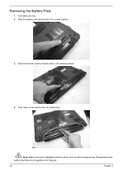
Turn base unit over. 2. Slide and hold the battery release latch to the unlock position. 3. Please detach the battery and follow local regulations for disposal. 42 Chapter 3 Note: Battery has been highlighted with the yellow circle as above image shows. Removing the Battery Pack 1. Then slide out the battery from the battery bay. Slide the battery lock/unlock latch to the release position. 4.
Turn base unit over. 2. Slide and hold the battery release latch to the unlock position. 3. Please detach the battery and follow local regulations for disposal. 42 Chapter 3 Note: Battery has been highlighted with the yellow circle as above image shows. Removing the Battery Pack 1. Then slide out the battery from the battery bay. Slide the battery lock/unlock latch to the release position. 4.

Aspire 5810TZ Service Guide
Page 51
Use a plastic screw driver to carefully pry open the lower cover. Torque 3.0 kgf-cm 4. Remove the lower cover from the lower case. Remove the four captive screws and four screws (H) securing the lower cover. 21 3 4 Step 1~4 Size (Quantity) M2.5 x L11 (4) Black Color 3. Chapter 3 43 Removing the Lower Cover 1. See "Removing the Battery Pack" on page 42. 2.
Use a plastic screw driver to carefully pry open the lower cover. Torque 3.0 kgf-cm 4. Remove the lower cover from the lower case. Remove the four captive screws and four screws (H) securing the lower cover. 21 3 4 Step 1~4 Size (Quantity) M2.5 x L11 (4) Black Color 3. Chapter 3 43 Removing the Lower Cover 1. See "Removing the Battery Pack" on page 42. 2.

Aspire 5810TZ Service Guide
Page 52
Remove the one screw (A) securing the optical drive. Step 1 Size (Quantity) M2.5 x L6 (1) Black Color Torque 3.0 kgf-cm 4. See "Removing the Battery Pack" on page 43. 3. Use a screw driver and carefully push out and slide out the optical drive module out of the bay. 44 Chapter 3 See "Removing the Lower Cover" on page 42. 2. Removing the Optical Drive Module 1.
Remove the one screw (A) securing the optical drive. Step 1 Size (Quantity) M2.5 x L6 (1) Black Color Torque 3.0 kgf-cm 4. See "Removing the Battery Pack" on page 43. 3. Use a screw driver and carefully push out and slide out the optical drive module out of the bay. 44 Chapter 3 See "Removing the Lower Cover" on page 42. 2. Removing the Optical Drive Module 1.

Aspire 5810TZ Service Guide
Page 53
Push out the latches on both sides of the DIMM socket to release the DIMM and remove it from the optical disk drive module. See "Removing the Lower Cover" on page 42. 2. 5. Chapter 3 45 See "Removing the Battery Pack" on page 43. 3. Remove the one screw (D) securing the locker bracket and remove the locker bracket from the socket. Step 1 Size (Quantity) M2 x L3 (1) Silver Color Torque 1.6 kgf-cm Removing the DIMM 1.
Push out the latches on both sides of the DIMM socket to release the DIMM and remove it from the optical disk drive module. See "Removing the Lower Cover" on page 42. 2. 5. Chapter 3 45 See "Removing the Battery Pack" on page 43. 3. Remove the one screw (D) securing the locker bracket and remove the locker bracket from the socket. Step 1 Size (Quantity) M2 x L3 (1) Silver Color Torque 1.6 kgf-cm Removing the DIMM 1.

Aspire 5810TZ Service Guide
Page 54
See "Removing the Battery Pack" on page 43. 3. NOTE: To prevent damage to the other socket if there is any DIMM present. Using the plastic tab, slide the hard disk drive module away from the bay. Removing the Hard Disk Drive Module 1. Do the same to device, avoid pressing down on it or placing heavy objects on top of it. 46 Chapter 3 See "Removing the Lower Cover" on page 42. 2. Lift up the hard disk module to remove from the connector. 4. 4.
See "Removing the Battery Pack" on page 43. 3. NOTE: To prevent damage to the other socket if there is any DIMM present. Using the plastic tab, slide the hard disk drive module away from the bay. Removing the Hard Disk Drive Module 1. Do the same to device, avoid pressing down on it or placing heavy objects on top of it. 46 Chapter 3 See "Removing the Lower Cover" on page 42. 2. Lift up the hard disk module to remove from the connector. 4. 4.

Aspire 5810TZ Service Guide
Page 56
... been highlighted with the yellow circle as above image shows. Removing the RTC Battery 1. NOTE: Be careful when removing the RTC battery. Please detach the battery and follow local regulations for disposal. 48 Chapter 3 Using the plastic tab, slide the SSD module away from the system. Removing the SSD ...Module 1. It is glued to remove it . Disconnect the RTC battery cable from the system board and lift to remove it from the connector and lift to the system board. See "Removing the Lower Cover" on...
... been highlighted with the yellow circle as above image shows. Removing the RTC Battery 1. NOTE: Be careful when removing the RTC battery. Please detach the battery and follow local regulations for disposal. 48 Chapter 3 Using the plastic tab, slide the SSD module away from the system. Removing the SSD ...Module 1. It is glued to remove it . Disconnect the RTC battery cable from the system board and lift to remove it from the connector and lift to the system board. See "Removing the Lower Cover" on...
Aspire 5810TZ Service Guide
Page 58
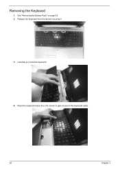
Carefully pry loose the keyboard. 4. Removing the Keyboard 1. See "Removing the Battery Pack" on page 42. 2. Place the keyboard below the LCD screen to gain access to the keyboard cable. 50 Chapter 3 Release the keyboard from the latches securing it. 3.
Carefully pry loose the keyboard. 4. Removing the Keyboard 1. See "Removing the Battery Pack" on page 42. 2. Place the keyboard below the LCD screen to gain access to the keyboard cable. 50 Chapter 3 Release the keyboard from the latches securing it. 3.

Aspire 5810TZ Service Guide
Page 59
Disconnect the antenna cables from the main board to remove the keyboard. See "Removing the Battery Pack" on page 50. 3. See "Removing the Keyboard" on page 42. 2. The Black antenna cable is connected to connector 1and the White antenna cable is connected to the WLAN board. NOTE: There are 2 antenna cables connected to connector 2. Chapter 3 51 Disconnect the keyboard cable from the WLAN board. Removing the WLAN Board Module 1. 5.
Disconnect the antenna cables from the main board to remove the keyboard. See "Removing the Battery Pack" on page 50. 3. See "Removing the Keyboard" on page 42. 2. The Black antenna cable is connected to connector 1and the White antenna cable is connected to the WLAN board. NOTE: There are 2 antenna cables connected to connector 2. Chapter 3 51 Disconnect the keyboard cable from the WLAN board. Removing the WLAN Board Module 1. 5.

Aspire 5810TZ Service Guide
Page 60
... 1.6 kgf-cm NOTE: When attaching the antenna back to release the WLAN board. Separating the Upper Case from the WLAN socket. See "Removing the RTC Battery" on the WLAN board to the WLAN board, make sure the cable are arranged properly. See "Removing the Optical Drive Module" on page 45. 6.... DIMM" on page 44. 5. See "Removing the WLAN Board Module" on page 42. 2. Detach the WLAN board from the Lower Case 1. See "Removing the Battery Pack" on page 51. 52 Chapter 3 See "Removing the Hard Disk Drive Module" on page 46. 7. Step 1 Size (Quantity) M2 x L4 (1) Black...
... 1.6 kgf-cm NOTE: When attaching the antenna back to release the WLAN board. Separating the Upper Case from the WLAN socket. See "Removing the RTC Battery" on the WLAN board to the WLAN board, make sure the cable are arranged properly. See "Removing the Optical Drive Module" on page 45. 6.... DIMM" on page 44. 5. See "Removing the WLAN Board Module" on page 42. 2. Detach the WLAN board from the Lower Case 1. See "Removing the Battery Pack" on page 51. 52 Chapter 3 See "Removing the Hard Disk Drive Module" on page 46. 7. Step 1 Size (Quantity) M2 x L4 (1) Black...


