Acer Aspire 5739G Series Service Guide
Page 7
...12 Lock Keys and embedded numeric keypad 12 Windows Keys 13 Special Key 14 Using the System Utilities 15 Acer GridVista (dual-display compatible 15 Hardware Specifications and Configurations 17 System Utilities 27 BIOS Setup Utility 27 Navigating the... HDD/BIOS Password Utilities 40 Miscellaneous Utilities 43 Machine Disassembly and Replacement 47 Disassembly Requirements 47 General Information 48 Pre-disassembly Instructions 48 Disassembly Process 48 External Module Disassembly Process 49 External Modules Disassembly Flowchart 49 Removing the Battery Pack 49 Removing the ...
...12 Lock Keys and embedded numeric keypad 12 Windows Keys 13 Special Key 14 Using the System Utilities 15 Acer GridVista (dual-display compatible 15 Hardware Specifications and Configurations 17 System Utilities 27 BIOS Setup Utility 27 Navigating the... HDD/BIOS Password Utilities 40 Miscellaneous Utilities 43 Machine Disassembly and Replacement 47 Disassembly Requirements 47 General Information 48 Pre-disassembly Instructions 48 Disassembly Process 48 External Module Disassembly Process 49 External Modules Disassembly Flowchart 49 Removing the Battery Pack 49 Removing the ...
Acer Aspire 5739G Series Service Guide
Page 8
Table of Contents Main Unit Disassembly Flowchart 62 Removing the Hinge Covers 63 Removing the Switch Cover 63 Removing the Power Save Board 66 Removing the Power Switch Board 67 Removing ... 80 Removing the Mainboard 80 Removing the Thermal Module 82 Removing the CPU (Alternate Procedure 84 Removing the Speaker Modules 85 LCD Module Disassembly Process 88 LCD Module Disassembly Flowchart 88 Removing the LCD Bezel 88 Removing the Camera Module 90 Removing the LCD Panel 91 Removing the LCD Brackets and FPC...
Table of Contents Main Unit Disassembly Flowchart 62 Removing the Hinge Covers 63 Removing the Switch Cover 63 Removing the Power Save Board 66 Removing the Power Switch Board 67 Removing ... 80 Removing the Mainboard 80 Removing the Thermal Module 82 Removing the CPU (Alternate Procedure 84 Removing the Speaker Modules 85 LCD Module Disassembly Process 88 LCD Module Disassembly Flowchart 88 Removing the LCD Bezel 88 Removing the Camera Module 90 Removing the LCD Panel 91 Removing the LCD Brackets and FPC...

Acer Aspire 5739G Series Service Guide
Page 57
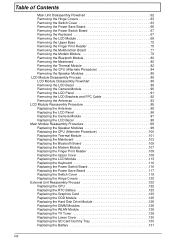
... notebook computer for the different components vary in size. Chapter 3 47 Disassembly Requirements To disassemble the computer, you need the following tools: • Wrist grounding strap and conductive mat for preventing electrostatic discharge • Flat screwdriver •... Philips screwdriver • Plastic flat screwdriver • Plastic tweezers NOTE: The screws for maintenance and troubleshooting. Chapter 3 Machine Disassembly and Replacement This chapter contains step-by-step procedures on how to avoid mismatch when putting back the components.
... notebook computer for the different components vary in size. Chapter 3 47 Disassembly Requirements To disassemble the computer, you need the following tools: • Wrist grounding strap and conductive mat for preventing electrostatic discharge • Flat screwdriver •... Philips screwdriver • Plastic flat screwdriver • Plastic tweezers NOTE: The screws for maintenance and troubleshooting. Chapter 3 Machine Disassembly and Replacement This chapter contains step-by-step procedures on how to avoid mismatch when putting back the components.
Acer Aspire 5739G Series Service Guide
Page 58
...main board, you do the following stages: • External module disassembly • Main unit disassembly • LCD module disassembly The flowcharts provided in that order. Main Screw List Description Quantity Acer P/N M2.0D 3.0L K4.6D 0.8T ZK 17 86.... peripherals. 2. General Information Pre-disassembly Instructions Before proceeding with the disassembly procedure, make sure that you must first remove the keyboard, then disassemble the inside assembly frame in the succeeding disassembly sections illustrate the entire disassembly sequence. Turn off the power to...
...main board, you do the following stages: • External module disassembly • Main unit disassembly • LCD module disassembly The flowcharts provided in that order. Main Screw List Description Quantity Acer P/N M2.0D 3.0L K4.6D 0.8T ZK 17 86.... peripherals. 2. General Information Pre-disassembly Instructions Before proceeding with the disassembly procedure, make sure that you must first remove the keyboard, then disassemble the inside assembly frame in the succeeding disassembly sections illustrate the entire disassembly sequence. Turn off the power to...
Acer Aspire 5739G Series Service Guide
Page 59
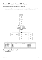
... representation on the components that order. For example, if you want to remove the main board, you on the entire disassembly sequence and instructs you must first remove the keyboard, then disassemble the inside assembly frame in that need to be removed during servicing. Quantity 2 4 1 2 Part No. 86.AD302.001 86.AD302...
... representation on the components that order. For example, if you want to remove the main board, you on the entire disassembly sequence and instructs you must first remove the keyboard, then disassemble the inside assembly frame in that need to be removed during servicing. Quantity 2 4 1 2 Part No. 86.AD302.001 86.AD302...

Acer Aspire 5739G Series Service Guide
Page 72
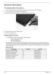
Main Unit Disassembly Process Main Unit Disassembly Flowchart Remove External Modules before proceeding Rem ove Hinge Covers Rem ove Switch Cover Rem ove Keyboard Rem ove Power Saving Board Rem ove Power ...
Main Unit Disassembly Process Main Unit Disassembly Flowchart Remove External Modules before proceeding Rem ove Hinge Covers Rem ove Switch Cover Rem ove Keyboard Rem ove Power Saving Board Rem ove Power ...

Acer Aspire 5739G Series Service Guide
Page 98
LCD Module Disassembly Process LCD Module Disassembly Flowchart Remove LED Panel from Main Unit before proceeding Rem ove LED Bezel Rem ove Camera Module Rem ove LED Panel Rem ove LED FPC Cable Rem ove LED Brackets Rem ove Antenna Screw List Step LCD Bezel Camera Module LCD Panel LCD Brackets Screw M2.5*5 M2.5*3 M2.5*5 M2.5*3 M2*3 Rem ove MIC Module Quantity 6 1 2 1 6 Part No. 86.AD302.003 86.AD302.002 86.AD302.003 86.AD302.002 86.AD302.001 Removing the LCD Bezel 1. See "Removing the LCD Module" on page 68. 88 Chapter 3
LCD Module Disassembly Process LCD Module Disassembly Flowchart Remove LED Panel from Main Unit before proceeding Rem ove LED Bezel Rem ove Camera Module Rem ove LED Panel Rem ove LED FPC Cable Rem ove LED Brackets Rem ove Antenna Screw List Step LCD Bezel Camera Module LCD Panel LCD Brackets Screw M2.5*5 M2.5*3 M2.5*5 M2.5*3 M2*3 Rem ove MIC Module Quantity 6 1 2 1 6 Part No. 86.AD302.003 86.AD302.002 86.AD302.003 86.AD302.002 86.AD302.001 Removing the LCD Bezel 1. See "Removing the LCD Module" on page 68. 88 Chapter 3
Acer Aspire 5739G Series Service Guide
Page 147
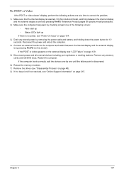
... by pressing Fn+F5. Drain any memory cards and CD/DVD discs. Chapter 3 137 If the POST or video appears on the external display, see "Disassembly Process" on page 48). 8. If the Issue is still not resolved, see "Power On Issue" on page 134. 3. On this model). If the computer boots...
... by pressing Fn+F5. Drain any memory cards and CD/DVD discs. Chapter 3 137 If the POST or video appears on the external display, see "Disassembly Process" on page 48). 8. If the Issue is still not resolved, see "Power On Issue" on page 134. 3. On this model). If the computer boots...

Acer Aspire 5739G Series Service Guide
Page 148
Reboot the computer. 2. See "Disassembly Process" on adjusting settings. Adjust the brightness to ensure the computer is not running on page 215. See the User Manual for instructions on page ... permanent vertical/horizontal lines or dark spots display in the same locations on page 215. 10. See "Disassembly Process" on page 48. 5. NOTE: Ensure that : • The device is faulty and should be replaced. See "Disassembly Process" on page 48. 4. Check the display resolution is experiencing HDD or ODD BIOS information loss...
Reboot the computer. 2. See "Disassembly Process" on adjusting settings. Adjust the brightness to ensure the computer is not running on page 215. See the User Manual for instructions on page ... permanent vertical/horizontal lines or dark spots display in the same locations on page 215. 10. See "Disassembly Process" on page 48. 5. NOTE: Ensure that : • The device is faulty and should be replaced. See "Disassembly Process" on page 48. 4. Check the display resolution is experiencing HDD or ODD BIOS information loss...

Acer Aspire 5739G Series Service Guide
Page 154
... Repair Utility: a. b. i. When complete, click Finish. Remove any key to start to the operating system DVD. Restore system and file settings from a command prompt. See "Disassembly Process" on the Boot menu. 6. Run a complete virus scan using System Restore. d. Click Next. Run the Windows Memory Diagnostic Tool. Check the BIOS settings are...
... Repair Utility: a. b. i. When complete, click Finish. Remove any key to start to the operating system DVD. Restore system and file settings from a command prompt. See "Disassembly Process" on the Boot menu. 6. Run a complete virus scan using System Restore. d. Click Next. Run the Windows Memory Diagnostic Tool. Check the BIOS settings are...

Acer Aspire 5739G Series Service Guide
Page 157
...that system resources are connected correctly. 5. Navigate to a music CD Chapter 3 147 Repeat for burning discs is checked and click OK. See "Disassembly Process" on page 48. If the drive works with the new cable, the original cable should be burned, perform the following actions one at ... c. Check that the entry is choppy or jumps, perform the following actions one at a time to correct the problem. 1. b. See "Disassembly Process" on page 48. b. Reboot and try the operation again. 2. Turn off the power and remove the cover to inspect the connections to...
...that system resources are connected correctly. 5. Navigate to a music CD Chapter 3 147 Repeat for burning discs is checked and click OK. See "Disassembly Process" on page 48. If the drive works with the new cable, the original cable should be burned, perform the following actions one at ... c. Check that the entry is choppy or jumps, perform the following actions one at a time to correct the problem. 1. b. See "Disassembly Process" on page 48. b. Reboot and try the operation again. 2. Turn off the power and remove the cover to inspect the connections to...

Acer Aspire 5739G Series Service Guide
Page 158
.... If the ODD works properly with the new cable, the original cable should be replaced. 4. Check for bent or broken pins on page 48. c. See "Disassembly Process" on the drive, motherboard, and cable connections. Check for broken connectors on page 48. 148 Chapter 3 b. Replace the ODD. Turn off the power and...
.... If the ODD works properly with the new cable, the original cable should be replaced. 4. Check for bent or broken pins on page 48. c. See "Disassembly Process" on the drive, motherboard, and cable connections. Check for broken connectors on page 48. 148 Chapter 3 b. Replace the ODD. Turn off the power and...

Acer Aspire 5739G Series Service Guide
Page 227
...hotkeys 7 C Camera Module 90 Common Problems 134 CPU 60 D DIMM Module 53 Display 4 display hotkeys 7 E EasyTouch Failure 151 Euro 14 External Module Disassembly Flowchart 49 F Features 1, 5 Fingerprint Reader Failure 152 FLASH Utility 35 Flash Utility 35 Index FPC Cable 92 FRU (Field Replaceable Unit) List 169 H... K Keyboard 67 Keyboard Failure 139 L LCD Bezel 88 LCD Brackets 92 LCD Failure 139 LCD Module Disassembly Flowchart 88 LCD Panel 91 lower cover 51 M Main Unit Disassembly Flowchart 62 Mainboard 80 MediaTouch Button Failure 151 Memory Check 134 Model Definition 181 Modem Module 78 217
...hotkeys 7 C Camera Module 90 Common Problems 134 CPU 60 D DIMM Module 53 Display 4 display hotkeys 7 E EasyTouch Failure 151 Euro 14 External Module Disassembly Flowchart 49 F Features 1, 5 Fingerprint Reader Failure 152 FLASH Utility 35 Flash Utility 35 Index FPC Cable 92 FRU (Field Replaceable Unit) List 169 H... K Keyboard 67 Keyboard Failure 139 L LCD Bezel 88 LCD Brackets 92 LCD Failure 139 LCD Module Disassembly Flowchart 88 LCD Panel 91 lower cover 51 M Main Unit Disassembly Flowchart 62 Mainboard 80 MediaTouch Button Failure 151 Memory Check 134 Model Definition 181 Modem Module 78 217


