Aspire 5680/5650/5630/5610/5610Z/3690 User's Guide
Page 39
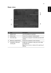
Houses the computer's hard disk (secured with screws). 21 Base view English # Item 1 Battery lock 2 Battery bay 3 Hard disk bay 4 Memory compartment 5 Ventilation slots and cooling fan Description Locks the battery in position. Enable the computer to stay cool, even after prolonged use. Note: Do not cover or obstruct the opening of the fan. Houses the computer's battery pack. Houses the computer's main memory.
Houses the computer's hard disk (secured with screws). 21 Base view English # Item 1 Battery lock 2 Battery bay 3 Hard disk bay 4 Memory compartment 5 Ventilation slots and cooling fan Description Locks the battery in position. Enable the computer to stay cool, even after prolonged use. Note: Do not cover or obstruct the opening of the fan. Houses the computer's battery pack. Houses the computer's main memory.

Aspire 5610 Service Guide
Page 11
The image above may not be exactly the same as the real main board you get. 1 JP19 FAN Connector 2 U42 VGA Chipset 3 JP18 CPU Socket 4 JP16 DVI Connector 5 JP15 CRT Connector 6 JP14 TV-Out Connector 7 PCN1 DC-IN Jack 8 JP17 Mini Card Connector 9 ... Bluetooth and 3G Switch South Bridge Chipset Mini Card Connector IEEE 1394 Connector 5 IN1 Socket RJ45 Connector USB Connector USB Connector MINIPCI Connector (TV-Tuner) FAN Connector North Bridge Chipset Chapter 1 5 Bottom View NOTE: This is engineering sample.
The image above may not be exactly the same as the real main board you get. 1 JP19 FAN Connector 2 U42 VGA Chipset 3 JP18 CPU Socket 4 JP16 DVI Connector 5 JP15 CRT Connector 6 JP14 TV-Out Connector 7 PCN1 DC-IN Jack 8 JP17 Mini Card Connector 9 ... Bluetooth and 3G Switch South Bridge Chipset Mini Card Connector IEEE 1394 Connector 5 IN1 Socket RJ45 Connector USB Connector USB Connector MINIPCI Connector (TV-Tuner) FAN Connector North Bridge Chipset Chapter 1 5 Bottom View NOTE: This is engineering sample.
Aspire 5610 Service Guide
Page 21
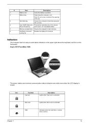
...4 5 6 Item Description Battery lock Locks the battery in position. Note: Do not cover or obstruct the opening of the fan. Ventilation slots and cooling fan Release the battery for TravelMate 4200) Memory compartment Houses the computer's main memory. Indicators The computer has four easy-to-read ... Battery bay Helps keep the computer cool. Hard disk bay Houses the computer's hard disk (secured with screws) Acer DASP (Disk Anti- Aspire 5610/TravelMate 4200: The power, battery and wireless communication status indicators are visible even when the LCD display is ...
...4 5 6 Item Description Battery lock Locks the battery in position. Note: Do not cover or obstruct the opening of the fan. Ventilation slots and cooling fan Release the battery for TravelMate 4200) Memory compartment Houses the computer's main memory. Indicators The computer has four easy-to-read ... Battery bay Helps keep the computer cool. Hard disk bay Houses the computer's hard disk (secured with screws) Acer DASP (Disk Anti- Aspire 5610/TravelMate 4200: The power, battery and wireless communication status indicators are visible even when the LCD display is ...
Aspire 5610 Service Guide
Page 63
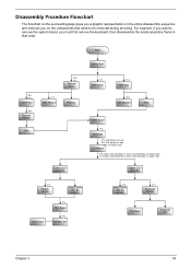
Start Battery Pack B*1 D*1 System Fan B*4 Thermal Module F*1 ODD Module CPU D*5 F*1 Thermal Door Memory Lower Case Assembly F*1 Mimi Cover F*2 HDD Door H*4 HDD Bracket HDD Middle Cover F*2 Keyboard C*2 LCD hinges to logic D*2 ...
Start Battery Pack B*1 D*1 System Fan B*4 Thermal Module F*1 ODD Module CPU D*5 F*1 Thermal Door Memory Lower Case Assembly F*1 Mimi Cover F*2 HDD Door H*4 HDD Bracket HDD Middle Cover F*2 Keyboard C*2 LCD hinges to logic D*2 ...
Aspire 5610 Service Guide
Page 66
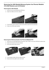
...from the main board. 56 Chapter 3 Pull the HDD module outwards to take out the fan cable as shown. 5. Take out the HDD module carefully. Detach the thermal door from the notebook. 3. Disconnect the fan cable from the main board. 4. M2*3(NL) for red circle; Remove the six ...screws fastening the thermal door. (M2.5*15(NL) for yellow circle) 2. Removing the HDD Module/Memory/System Fan/Thermal Module/ CPU/ODD Module and LCD Module Removing...
...from the main board. 56 Chapter 3 Pull the HDD module outwards to take out the fan cable as shown. 5. Take out the HDD module carefully. Detach the thermal door from the notebook. 3. Disconnect the fan cable from the main board. 4. M2*3(NL) for red circle; Remove the six ...screws fastening the thermal door. (M2.5*15(NL) for yellow circle) 2. Removing the HDD Module/Memory/System Fan/Thermal Module/ CPU/ODD Module and LCD Module Removing...
Aspire 5610 Service Guide
Page 67
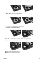
Use a flat-headed screwdriver to release the CPU lock (Turn anti-clockwise). 11. Chapter 3 57 Then detach the thermal module carefully. 10. Detach the CPU from the main unit. 8. Then remove the antenna protection cover. 6. Remove the two screws fastening the system fan. 7. Remove the four screws fastening the thermal module. 9. Tear off the tape fastening the antenna set. 13. Take out the system fan from the CPU socket carefully. 12.
Use a flat-headed screwdriver to release the CPU lock (Turn anti-clockwise). 11. Chapter 3 57 Then detach the thermal module carefully. 10. Detach the CPU from the main unit. 8. Then remove the antenna protection cover. 6. Remove the two screws fastening the system fan. 7. Remove the four screws fastening the thermal module. 9. Tear off the tape fastening the antenna set. 13. Take out the system fan from the CPU socket carefully. 12.

Aspire 5610 Service Guide
Page 96
Bottom View NOTE: This is engineering sample. The image above may not be exactly the same as the real main board you get. 1 JP19 FAN Connector 2 U42 VGA Chipset 3 JP18 CPU Socket 4 JP16 DVI Connector 5 JP15 CRT Connector 6 JP14 TV-Out Connector 7 PCN1 DC-IN Jack 8 JP17 Mini Card Connector 9 ... Bluetooth and 3G Switch South Bridge Chipset Mini Card Connector IEEE 1394 Connector 5 IN1 Socket RJ45 Connector USB Connector USB Connector MINIPCI Connector (TV-Tuner) FAN Connector North Bridge Chipset 86 Chapter 5
Bottom View NOTE: This is engineering sample. The image above may not be exactly the same as the real main board you get. 1 JP19 FAN Connector 2 U42 VGA Chipset 3 JP18 CPU Socket 4 JP16 DVI Connector 5 JP15 CRT Connector 6 JP14 TV-Out Connector 7 PCN1 DC-IN Jack 8 JP17 Mini Card Connector 9 ... Bluetooth and 3G Switch South Bridge Chipset Mini Card Connector IEEE 1394 Connector 5 IN1 Socket RJ45 Connector USB Connector USB Connector MINIPCI Connector (TV-Tuner) FAN Connector North Bridge Chipset 86 Chapter 5

Aspire 5610 Service Guide
Page 108
... RUBBER THERMAL DOOR RUBBER POINTING DEVICE TOUCHPAD W/SPONGE NAME PLATE - LARGE RUBBER FOOT - TM4200 RUBBER FOOT - MIDDLE RUBBER FOOT - CATEGORY FAN PARTNAME MEMORY 512MB DDR II 533 NANYA NT512T64UHA1FN-37B MEMORY 512MB DDR II 533 INFINEON HYS64T64020HDL-3.7-A MEMORY 512MB DDR II 533 MICRON MT8HTF6464HDY-53EB3 ...MEMORY 512MB DDR II 533 SAMSUNG M470T6554CZ3-CD500 MEMORY 512MB DDR II 533 HYNIX HYMP564S64P6-C4 Acer PN KN.51203.023 KN.51202.021 KN.51204.019 KN.5120B.015 KN.5120G.005 FAN ASSY - CPU THERMAL MODULE - UMA 23.TAVV5.001 HEATSINK THERMAL MODULE - LARGE ...
... RUBBER THERMAL DOOR RUBBER POINTING DEVICE TOUCHPAD W/SPONGE NAME PLATE - LARGE RUBBER FOOT - TM4200 RUBBER FOOT - MIDDLE RUBBER FOOT - CATEGORY FAN PARTNAME MEMORY 512MB DDR II 533 NANYA NT512T64UHA1FN-37B MEMORY 512MB DDR II 533 INFINEON HYS64T64020HDL-3.7-A MEMORY 512MB DDR II 533 MICRON MT8HTF6464HDY-53EB3 ...MEMORY 512MB DDR II 533 SAMSUNG M470T6554CZ3-CD500 MEMORY 512MB DDR II 533 HYNIX HYMP564S64P6-C4 Acer PN KN.51203.023 KN.51202.021 KN.51204.019 KN.5120B.015 KN.5120G.005 FAN ASSY - CPU THERMAL MODULE - UMA 23.TAVV5.001 HEATSINK THERMAL MODULE - LARGE ...


