Acer Aspire 5542 Notebook Series Service Guide
Page 7
...keypad 13 Windows Keys 14 Hot Keys 15 Special Key (only for certain models 16 Using the System Utilities 17 Acer GridVista (dual-display compatible 17 Hardware Specifications and Configurations 19 System Utilities 27 BIOS Setup Utility 27 Navigating the ... 38 BIOS Flash Utility 39 Remove HDD Password 40 Machine Disassembly and Replacement 41 Disassembly Requirements 41 General Information 42 Pre-disassembly Instructions 42 Disassembly Process 42 External Module Disassembly Process 43 External Modules Disassembly Flowchart 43 Removing the Battery Pack 44 Removing the SD ...
...keypad 13 Windows Keys 14 Hot Keys 15 Special Key (only for certain models 16 Using the System Utilities 17 Acer GridVista (dual-display compatible 17 Hardware Specifications and Configurations 19 System Utilities 27 BIOS Setup Utility 27 Navigating the ... 38 BIOS Flash Utility 39 Remove HDD Password 40 Machine Disassembly and Replacement 41 Disassembly Requirements 41 General Information 42 Pre-disassembly Instructions 42 Disassembly Process 42 External Module Disassembly Process 43 External Modules Disassembly Flowchart 43 Removing the Battery Pack 44 Removing the SD ...

Acer Aspire 5542 Notebook Series Service Guide
Page 8
...Main Board 77 Removing the Heatsink Module 79 Removing the CPU 81 LCD Module Disassembly Process 83 LCD Module Disassembly Flowchart 83 Removing the LCD Bezel 84 Removing the Inverter Board (Aspire 5738DG/5738DZG Series only 86 Removing the LCD panel with the Brackets 88 ... List 121 Exploded Diagram 122 FRU List 123 Model Definition and Configuration 214 Aspire 5738G/5738ZG/5738Z/5738/5338 Series 215 Aspire 5536/5536G/5236 Series 235 Aspire 5738DG/5738DZG Series 249 Aspire 5542G/5542/5242 Series 263 Test Compatible Components 291 Microsoft® Windows® Environment ...
...Main Board 77 Removing the Heatsink Module 79 Removing the CPU 81 LCD Module Disassembly Process 83 LCD Module Disassembly Flowchart 83 Removing the LCD Bezel 84 Removing the Inverter Board (Aspire 5738DG/5738DZG Series only 86 Removing the LCD panel with the Brackets 88 ... List 121 Exploded Diagram 122 FRU List 123 Model Definition and Configuration 214 Aspire 5738G/5738ZG/5738Z/5738/5338 Series 215 Aspire 5536/5536G/5236 Series 235 Aspire 5738DG/5738DZG Series 249 Aspire 5542G/5542/5242 Series 263 Test Compatible Components 291 Microsoft® Windows® Environment ...

Acer Aspire 5542 Notebook Series Service Guide
Page 49
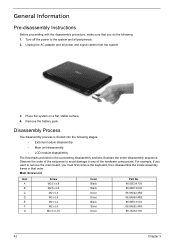
... • Plastic tweezers NOTE: The screws for maintenance and troubleshooting. Chapter 3 41 During the disassembly process, group the screws with the corresponding components to disassemble the notebook computer for the different components vary in size. Chapter 3 Machine Disassembly and Replacement This chapter contains step-by-step procedures on how to avoid mismatch when...
... • Plastic tweezers NOTE: The screws for maintenance and troubleshooting. Chapter 3 41 During the disassembly process, group the screws with the corresponding components to disassemble the notebook computer for the different components vary in size. Chapter 3 Machine Disassembly and Replacement This chapter contains step-by-step procedures on how to avoid mismatch when...
Acer Aspire 5542 Notebook Series Service Guide
Page 50
... main board, you do the following stages: • External module disassembly • Main unit disassembly • LCD module disassembly The flowcharts provided in that you must first remove the keyboard, then disassemble the inside assembly frame in the succeeding disassembly sections illustrate the entire disassembly sequence. Turn off the power to any of the hardware components...
... main board, you do the following stages: • External module disassembly • Main unit disassembly • LCD module disassembly The flowcharts provided in that you must first remove the keyboard, then disassemble the inside assembly frame in the succeeding disassembly sections illustrate the entire disassembly sequence. Turn off the power to any of the hardware components...

Acer Aspire 5542 Notebook Series Service Guide
Page 51
...if you want to remove the main board, you on the entire disassembly sequence and instructs you must first remove the keyboard, then disassemble the inside assembly frame in that need to be removed during servicing. EXTERNAL MODULE DISASSEMBLY TURN OFF POWER AND PERIPHERALS UNPLUG POWER CABLES REMOVE BATTERY PACK SD ...L8 M3 x L4 M2 x L4 Color Black Silver Silver Part No. 86.00E34.738 86.9A554.4R0 86.9A552.4R0 Chapter 3 43 External Module Disassembly Process External Modules Disassembly Flowchart The flowchart below gives you a graphic representation on the components that order.
...if you want to remove the main board, you on the entire disassembly sequence and instructs you must first remove the keyboard, then disassemble the inside assembly frame in that need to be removed during servicing. EXTERNAL MODULE DISASSEMBLY TURN OFF POWER AND PERIPHERALS UNPLUG POWER CABLES REMOVE BATTERY PACK SD ...L8 M3 x L4 M2 x L4 Color Black Silver Silver Part No. 86.00E34.738 86.9A554.4R0 86.9A552.4R0 Chapter 3 43 External Module Disassembly Process External Modules Disassembly Flowchart The flowchart below gives you a graphic representation on the components that order.

Acer Aspire 5542 Notebook Series Service Guide
Page 63
Main Unit Disassembly Process Main Unit Disassembly Flowchart MAIN UNIT DISASSEMBLY MAIN UNIT MIDDLE COVER F x 1 VOLUME BUTTON BOARD KEYBOARD Ax2 Gx2 LCD MODULE A x 10 F x 3 UPPER CASE Ex1 RIGHT SPEAKER MODULE BLUETOOTH MODULE Fx1 MODEM CARD FINGERPRINT MODULE Fx1 USB MODULE TOUCHPAD MODULE Ex2 LEFT SPEAKER MODULE Fx1 MAIN BOARD SCREW X 6 HEATSINK MODULE CPU Screw List Item A E F G Screw M2.5 x L8 M2 x L4 M2 x L4 M2.5 x L10 Color Black Black Silver Silver Part No. 86.00E34.738 86.00E13.524 86.9A552.4R0 86.1A553.100 Chapter 3 55
Main Unit Disassembly Process Main Unit Disassembly Flowchart MAIN UNIT DISASSEMBLY MAIN UNIT MIDDLE COVER F x 1 VOLUME BUTTON BOARD KEYBOARD Ax2 Gx2 LCD MODULE A x 10 F x 3 UPPER CASE Ex1 RIGHT SPEAKER MODULE BLUETOOTH MODULE Fx1 MODEM CARD FINGERPRINT MODULE Fx1 USB MODULE TOUCHPAD MODULE Ex2 LEFT SPEAKER MODULE Fx1 MAIN BOARD SCREW X 6 HEATSINK MODULE CPU Screw List Item A E F G Screw M2.5 x L8 M2 x L4 M2 x L4 M2.5 x L10 Color Black Black Silver Silver Part No. 86.00E34.738 86.00E13.524 86.9A552.4R0 86.1A553.100 Chapter 3 55
Acer Aspire 5542 Notebook Series Service Guide
Page 305
... by Crisis Disk 117 steps 117 BIOS Recovery Hotkey 117 BIOS Utility 27-39 Navigating 28 Security 32 System Security 38 block diagram Aspire 5536/5536G/5236 Series 5 Aspire 5738G/5738ZG/5738Z/5738/5338 Series 4, 6 brightness hotkeys 15 button/indicator 3G WWAN 7, 12 bluetooth 7, 12 wireless LAN 7, 12 buttons ...creating 117 D DIMM Module 46 display hotkeys 15 E Error Symptom-to-Spare Part Index 98 Euro 16 External CD-ROM Drive Check 96 External Module Disassembly Flowchart 43 F Flash Utility 39 FRU (Field Replaceable Unit) List 121 H Hard disk 21 Hard Disk Drive Module 48 HDD 21 Hibernation mode ...
... by Crisis Disk 117 steps 117 BIOS Recovery Hotkey 117 BIOS Utility 27-39 Navigating 28 Security 32 System Security 38 block diagram Aspire 5536/5536G/5236 Series 5 Aspire 5738G/5738ZG/5738Z/5738/5338 Series 4, 6 brightness hotkeys 15 button/indicator 3G WWAN 7, 12 bluetooth 7, 12 wireless LAN 7, 12 buttons ...creating 117 D DIMM Module 46 display hotkeys 15 E Error Symptom-to-Spare Part Index 98 Euro 16 External CD-ROM Drive Check 96 External Module Disassembly Flowchart 43 F Flash Utility 39 FRU (Field Replaceable Unit) List 121 H Hard disk 21 Hard Disk Drive Module 48 HDD 21 Hibernation mode ...
Acer Aspire 5542 Notebook Series Service Guide
Page 306
... removing 58 Keyboard or Auxiliary Input Device Check 96 L LCD bezel removing 84 LCD Brackets removing 89 LCD Module Disassembly Flowchart 83 LCD with the brackets removing 88 M Main 113 Main Unit Disassembly Flowchart 55 media access on indicator 8 Memory Check 97 Menu Boot 37 menu Exit 38 Information 29 Security 33...
... removing 58 Keyboard or Auxiliary Input Device Check 96 L LCD bezel removing 84 LCD Brackets removing 89 LCD Module Disassembly Flowchart 83 LCD with the brackets removing 88 M Main 113 Main Unit Disassembly Flowchart 55 media access on indicator 8 Memory Check 97 Menu Boot 37 menu Exit 38 Information 29 Security 33...


