Acer Aspire 5538 Series Service Guide
Page 7
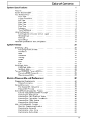
... 37 Removing BIOS Passwords 38 Miscellaneous Utilities 39 Machine Disassembly and Replacement 42 Disassembly Requirements 42 Related Information 42 General Information 43 Pre-disassembly Instructions 43 Disassembly Process 43 External Module Disassembly Process 44 External Modules Disassembly Flowchart 44 Removing the Battery Pack 45 Removing the ... Drive Module 49 Removing the DIMM Module 52 Removing the WLAN Board 55 Main Unit Disassembly Process 58 Main Unit Disassembly Flowchart 58 Removing the Keyboard 60 Removing the Upper Cover 62 Removing the Button Board 66 VII
... 37 Removing BIOS Passwords 38 Miscellaneous Utilities 39 Machine Disassembly and Replacement 42 Disassembly Requirements 42 Related Information 42 General Information 43 Pre-disassembly Instructions 43 Disassembly Process 43 External Module Disassembly Process 44 External Modules Disassembly Flowchart 44 Removing the Battery Pack 45 Removing the ... Drive Module 49 Removing the DIMM Module 52 Removing the WLAN Board 55 Main Unit Disassembly Process 58 Main Unit Disassembly Flowchart 58 Removing the Keyboard 60 Removing the Upper Cover 62 Removing the Button Board 66 VII
Acer Aspire 5538 Series Service Guide
Page 8
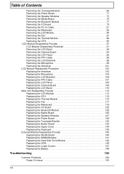
... the Mainboard 82 Removing the LCD Module 85 Removing the Fan 87 Removing the Thermal Module 89 Removing the CPU 90 LCD Module Disassembly Process 91 LCD Module Disassembly Flowchart 91 Removing the LCD Bezel 92 Removing the Camera Board 94 Removing the LCD Panel 95 Removing the FPC Cable 96 Removing...
... the Mainboard 82 Removing the LCD Module 85 Removing the Fan 87 Removing the Thermal Module 89 Removing the CPU 90 LCD Module Disassembly Process 91 LCD Module Disassembly Flowchart 91 Removing the LCD Bezel 92 Removing the Camera Board 94 Removing the LCD Panel 95 Removing the FPC Cable 96 Removing...
Acer Aspire 5538 Series Service Guide
Page 52
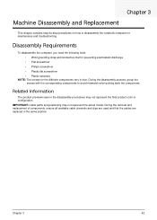
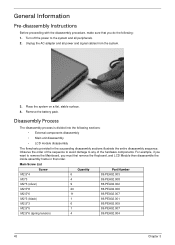
...notebook computer for the different components vary in the same position. Related Information The product previews seen in the disassembly procedures may not represent the actual model. During the removal and replacement of components, ensure all available cable... that the cables are replaced in size. IMPORTANT: Cable paths and positioning may not represent the final product color or configuration. Disassembly Requirements To disassemble the computer, you need the following tools: • Wrist grounding strap and conductive mat for preventing electrostatic discharge • Flat...
...notebook computer for the different components vary in the same position. Related Information The product previews seen in the disassembly procedures may not represent the actual model. During the removal and replacement of components, ensure all available cable... that the cables are replaced in size. IMPORTANT: Cable paths and positioning may not represent the final product color or configuration. Disassembly Requirements To disassemble the computer, you need the following tools: • Wrist grounding strap and conductive mat for preventing electrostatic discharge • Flat...
Acer Aspire 5538 Series Service Guide
Page 53
..., make sure that order. Place the system on a flat, stable surface. 4. Disassembly Process The disassembly process is divided into the following : 1. Remove the battery pack. Main Screw List Screw Quantity Part Number M2.5*4 6 86.... the Keyboard, and LCD Module then disassemble the inside assembly frame in that you do the following sections: • External components disassembly • Main unit disassembly • LCD module disassembly The flowcharts provided in the succeeding disassembly sections illustrate the entire disassembly sequence. Turn off the power to any...
..., make sure that order. Place the system on a flat, stable surface. 4. Disassembly Process The disassembly process is divided into the following : 1. Remove the battery pack. Main Screw List Screw Quantity Part Number M2.5*4 6 86.... the Keyboard, and LCD Module then disassemble the inside assembly frame in that you do the following sections: • External components disassembly • Main unit disassembly • LCD module disassembly The flowcharts provided in the succeeding disassembly sections illustrate the entire disassembly sequence. Turn off the power to any...
Acer Aspire 5538 Series Service Guide
Page 54
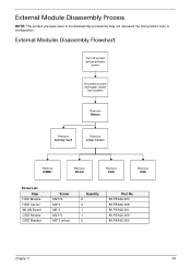
External Modules Disassembly Flowchart Turn off system and peripherals power Disconnect power and signal cables from system Remove Battery Remove Dummy Card Remove Lower Covers Remove DIMMs Remove ...*3 M2.5*3 M2*3 (silver) Quantity 2 4 1 1 2 Part No. 86.PEA02.003 86.PEA02.008 86.PEA02.001 86.PEA02.009 86.PEA02.002 Chapter 3 44 External Module Disassembly Process NOTE: The product previews seen in the disassembly procedures may not represent the final product color or configuration.
External Modules Disassembly Flowchart Turn off system and peripherals power Disconnect power and signal cables from system Remove Battery Remove Dummy Card Remove Lower Covers Remove DIMMs Remove ...*3 M2.5*3 M2*3 (silver) Quantity 2 4 1 1 2 Part No. 86.PEA02.003 86.PEA02.008 86.PEA02.001 86.PEA02.009 86.PEA02.002 Chapter 3 44 External Module Disassembly Process NOTE: The product previews seen in the disassembly procedures may not represent the final product color or configuration.
Acer Aspire 5538 Series Service Guide
Page 68
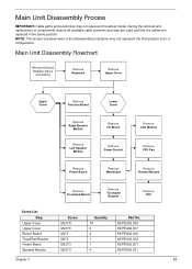
NOTE: The product previews seen in the same position. Main Unit Disassembly Flowchart Remove External Modules before proceeding Remove Keyboard Remove Upper Cover Upper Cover Remove Function Board Lower Cover Remove Right Speaker Module Remove Left Speaker ... 18 6 4 1 1 4 Part No. 86.PEA02.006 86.PEA02.007 86.PEA02.002 86.PEA02.002 86.PEA02.001 86.PEA02.001 Chapter 3 58 Main Unit Disassembly Process IMPORTANT: Cable paths and positioning may not represent the final product color or configuration. During the removal and replacement of components, ensure all available...
NOTE: The product previews seen in the same position. Main Unit Disassembly Flowchart Remove External Modules before proceeding Remove Keyboard Remove Upper Cover Upper Cover Remove Function Board Lower Cover Remove Right Speaker Module Remove Left Speaker ... 18 6 4 1 1 4 Part No. 86.PEA02.006 86.PEA02.007 86.PEA02.002 86.PEA02.002 86.PEA02.001 86.PEA02.001 Chapter 3 58 Main Unit Disassembly Process IMPORTANT: Cable paths and positioning may not represent the final product color or configuration. During the removal and replacement of components, ensure all available...
Acer Aspire 5538 Series Service Guide
Page 72
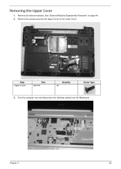
Removing the Upper Cover 1. Remove the screws securing the Upper Cover to the Lower Cover. Step Upper Cover Size M2.5*8 Quantity 18 Screw Type 3. Turn the computer over and disconnect the following cables from the Mainboard: Chapter 3 62 See "External Modules Disassembly Flowchart" on page 44. 2. Remove all external modules.
Removing the Upper Cover 1. Remove the screws securing the Upper Cover to the Lower Cover. Step Upper Cover Size M2.5*8 Quantity 18 Screw Type 3. Turn the computer over and disconnect the following cables from the Mainboard: Chapter 3 62 See "External Modules Disassembly Flowchart" on page 44. 2. Remove all external modules.
Acer Aspire 5538 Series Service Guide
Page 101
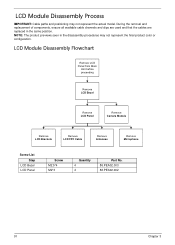
LCD Module Disassembly Flowchart Remove LCD Panel from Main Unit before proceeding Remove LCD Bezel Remove LCD Panel Remove Camera Module Remove LCD Brackets Remove LCD FPC Cable ... position. During the removal and replacement of components, ensure all available cable channels and clips are used and that the cables are replaced in the disassembly procedures may not represent the actual model. LCD Module Disassembly Process IMPORTANT: Cable paths and positioning may not represent the final product color or configuration.
LCD Module Disassembly Flowchart Remove LCD Panel from Main Unit before proceeding Remove LCD Bezel Remove LCD Panel Remove Camera Module Remove LCD Brackets Remove LCD FPC Cable ... position. During the removal and replacement of components, ensure all available cable channels and clips are used and that the cables are replaced in the disassembly procedures may not represent the actual model. LCD Module Disassembly Process IMPORTANT: Cable paths and positioning may not represent the final product color or configuration.
Acer Aspire 5538 Series Service Guide
Page 164
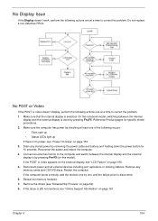
... display and the external display is done by checking at a time to correct the problem. 1. Make sure that the internal display is no power, see "Disassembly Process" on page 153. 3. Drain any memory cards and CD/DVD discs. Connect an external monitor to the computer and switch between the internal display...
... display and the external display is done by checking at a time to correct the problem. 1. Make sure that the internal display is no power, see "Disassembly Process" on page 153. 3. Drain any memory cards and CD/DVD discs. Connect an external monitor to the computer and switch between the internal display...
Acer Aspire 5538 Series Service Guide
Page 165
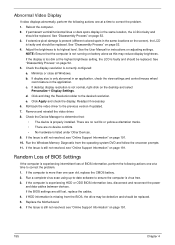
... not resolved, see "Online Support Information" on page 52. 3. If the Issue is virus free. 3. Reboot the computer. 2. See "Disassembly Process" on page 191. 10. NOTE: Ensure that : • The device is experiencing intermittent loss of BIOS Settings If the computer is... If video displays abnormally, perform the following actions one at a time to correct the problem. 1. d. Replace the Motherboard. 6. e. See "Disassembly Process" on the desktop and select Personalize´ Display Settings. If desktop display resolution is more than one year old, replace the CMOS battery...
... not resolved, see "Online Support Information" on page 52. 3. If the Issue is virus free. 3. Reboot the computer. 2. See "Disassembly Process" on page 191. 10. NOTE: Ensure that : • The device is experiencing intermittent loss of BIOS Settings If the computer is... If video displays abnormally, perform the following actions one at a time to correct the problem. 1. d. Replace the Motherboard. 6. e. See "Disassembly Process" on the desktop and select Personalize´ Display Settings. If desktop display resolution is more than one year old, replace the CMOS battery...
Acer Aspire 5538 Series Service Guide
Page 170
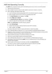
... see Windows Help and Support. 10. When prompted, press any recently added hardware and associated software. 8. Restore system and file settings from a command prompt. f. See "Disassembly Process" on page 52. For more information see Windows Help and Support. 5. Run Windows Check Disk by entering chkdsk /r from a known good date using up...
... see Windows Help and Support. 10. When prompted, press any recently added hardware and associated software. 8. Restore system and file settings from a command prompt. f. See "Disassembly Process" on page 52. For more information see Windows Help and Support. 5. Run Windows Check Disk by entering chkdsk /r from a known good date using up...
Acer Aspire 5538 Series Service Guide
Page 173
...in the ATAPI Model Name field on the drive, motherboard, and cables. Retry reading the CD or DVD. Play a DVD movie f. See "Disassembly Process" on page 52. Navigate to enter the BIOS Utility. 2. Ensure that the drive is identical to one at a time to the ODD... Read Failure If discs cannot be replaced. 3. d. b. Repeat for the other discs. See "Disassembly Process" on page 52. 163 Chapter 4 See "Disassembly Process" on page 52. See "Disassembly Process" on page 52. If the drive works with alternate discs, the original disc is checked and...
...in the ATAPI Model Name field on the drive, motherboard, and cables. Retry reading the CD or DVD. Play a DVD movie f. See "Disassembly Process" on page 52. Navigate to enter the BIOS Utility. 2. Ensure that the drive is identical to one at a time to the ODD... Read Failure If discs cannot be replaced. 3. d. b. Repeat for the other discs. See "Disassembly Process" on page 52. 163 Chapter 4 See "Disassembly Process" on page 52. See "Disassembly Process" on page 52. If the drive works with alternate discs, the original disc is checked and...

Acer Aspire 5538 Series Service Guide
Page 223
... CPU Fan Replacing 117 Index D DC-In Cable Removing 81 DIMM Module Removing 52 Replacing 141 Display 4 display hotkeys 13 E Euro Key 14 External Module Disassembly Flowchart 44 F Fan Removing 87 Replacing 117 Features 1 FLASH Utility 34 Flash Utility 34 FPC Cable Removing 96 Replacing 107 FRU (Field Replaceable Unit) List...
... CPU Fan Replacing 117 Index D DC-In Cable Removing 81 DIMM Module Removing 52 Replacing 141 Display 4 display hotkeys 13 E Euro Key 14 External Module Disassembly Flowchart 44 F Fan Removing 87 Replacing 117 Features 1 FLASH Utility 34 Flash Utility 34 FPC Cable Removing 96 Replacing 107 FRU (Field Replaceable Unit) List...
Acer Aspire 5538 Series Service Guide
Page 224
... Removing 98 Replacing 106 LCD Cable Removing 96, 107 LCD Failure 156 LCD Module Disassembly 91 Reassembly 103 Removing 85 Replacing 113 LCD Module Disassembly Flowchart 91 LCD Panel Removing 95 Replacing 108 Lower Covers Replacing 147 M Main Unit Disassembly Flowchart 58 Mainboard Removing 82 Replacing 119 media access on indicator 9 Media Board...
... Removing 98 Replacing 106 LCD Cable Removing 96, 107 LCD Failure 156 LCD Module Disassembly 91 Reassembly 103 Removing 85 Replacing 113 LCD Module Disassembly Flowchart 91 LCD Panel Removing 95 Replacing 108 Lower Covers Replacing 147 M Main Unit Disassembly Flowchart 58 Mainboard Removing 82 Replacing 119 media access on indicator 9 Media Board...


