Aspire 5235 / 5535 Service Guide
Page 7
...Keyboard 11 Lock Keys and embedded numeric keypad 11 Windows Keys 12 Hot Keys 13 Special Key (only for certain models 14 Acer Empowering Technology 15 Launching Acer Empowering Technology 15 Empowering Technology password 16 Acer eAudio Management (only for certain models 17 Acer ePower Management 18 Acer... Disassembly Flowchart 49 Removing the Battery Pack 50 Removing the SD dummy card 51 Removing the ExpressCard dummy card 51 Removing the Lower Cover 52 Removing the DIMM 53 Removing the WLAN Board Modules 54 Removing the Hard Disk Drive Module 56 Removing the Optical Drive ...
...Keyboard 11 Lock Keys and embedded numeric keypad 11 Windows Keys 12 Hot Keys 13 Special Key (only for certain models 14 Acer Empowering Technology 15 Launching Acer Empowering Technology 15 Empowering Technology password 16 Acer eAudio Management (only for certain models 17 Acer ePower Management 18 Acer... Disassembly Flowchart 49 Removing the Battery Pack 50 Removing the SD dummy card 51 Removing the ExpressCard dummy card 51 Removing the Lower Cover 52 Removing the DIMM 53 Removing the WLAN Board Modules 54 Removing the Hard Disk Drive Module 56 Removing the Optical Drive ...
Aspire 5235 / 5535 Service Guide
Page 8
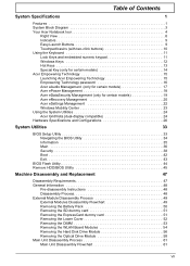
...Removing the Middle Cover 62 Removing the Keyboard 63 Removing the Heatsink Fan Module 64 Removing the CPU Heatsink Module 65 Removing the CPU 66 Removing the LCD Module 67 Separating the Upper Case from the Lower Case 70 Removing the LED Board 73 Removing the Speaker Module 75 Removing the Touchpad Module 77 Removing the Modem Board 80 Removing... by Crisis Disk 120 FRU (Field Replaceable Unit) List 121 Aspire 5235/5535 Series Exploded Diagram 122 Model Definition and Configuration 130 Aspire 5235/5535 Series 130 Test Compatible Components 155 Microsoft® Windows®...
...Removing the Middle Cover 62 Removing the Keyboard 63 Removing the Heatsink Fan Module 64 Removing the CPU Heatsink Module 65 Removing the CPU 66 Removing the LCD Module 67 Separating the Upper Case from the Lower Case 70 Removing the LED Board 73 Removing the Speaker Module 75 Removing the Touchpad Module 77 Removing the Modem Board 80 Removing... by Crisis Disk 120 FRU (Field Replaceable Unit) List 121 Aspire 5235/5535 Series Exploded Diagram 122 Model Definition and Configuration 130 Aspire 5235/5535 Series 130 Test Compatible Components 155 Microsoft® Windows®...

Aspire 5235 / 5535 Service Guide
Page 60
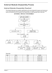
...all power and signal cables from the system. 3. For example, if you want to any of the sequence to avoid damage to remove the main board, you do the following stages: • External module disassembly • Main unit disassembly • LCD module ...disassembly The flowcharts provided in that you must first remove the keyboard, then disassemble the inside assembly frame in the succeeding disassembly sections illustrate the entire disassembly sequence. Observe the order of the hardware...
...all power and signal cables from the system. 3. For example, if you want to any of the sequence to avoid damage to remove the main board, you do the following stages: • External module disassembly • Main unit disassembly • LCD module ...disassembly The flowcharts provided in that you must first remove the keyboard, then disassemble the inside assembly frame in the succeeding disassembly sections illustrate the entire disassembly sequence. Observe the order of the hardware...
Aspire 5235 / 5535 Service Guide
Page 61
EXTERNAL MODULE DISASSEMBLY TURN OFF POWER AND PERIPHERALS UNPLUG POWER CABLES REMOVE BATTERY PACK SD DUMMY CARD ExpressCard DUMMY CARD Captive Screwx4 Ax6 LOWER COVER Hx1 WLAN BOARD DIMM MODULES ODD MODULE Cx1 HDD MODULE OPTICAL DISK ... flowchart below gives you a graphic representation on the entire disassembly sequence and instructs you on the components that order. For example, if you must first remove the keyboard, then disassemble the inside assembly frame in that need to...
EXTERNAL MODULE DISASSEMBLY TURN OFF POWER AND PERIPHERALS UNPLUG POWER CABLES REMOVE BATTERY PACK SD DUMMY CARD ExpressCard DUMMY CARD Captive Screwx4 Ax6 LOWER COVER Hx1 WLAN BOARD DIMM MODULES ODD MODULE Cx1 HDD MODULE OPTICAL DISK ... flowchart below gives you a graphic representation on the entire disassembly sequence and instructs you on the components that order. For example, if you must first remove the keyboard, then disassemble the inside assembly frame in that need to...
Aspire 5235 / 5535 Service Guide
Page 75
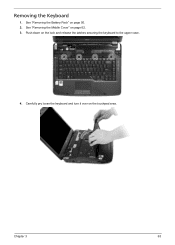
Push down on page 50. 2. See "Removing the Battery Pack" on the lock and release the latches securing the keyboard to the upper case. 4. Carefully pry loose the keyboard and turn it over on page 62. 3. Chapter 3 63 See "Removing the Middle Cover" on the touchpad area. Removing the Keyboard 1.
Push down on page 50. 2. See "Removing the Battery Pack" on the lock and release the latches securing the keyboard to the upper case. 4. Carefully pry loose the keyboard and turn it over on page 62. 3. Chapter 3 63 See "Removing the Middle Cover" on the touchpad area. Removing the Keyboard 1.
Aspire 5235 / 5535 Service Guide
Page 76
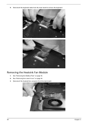
Disconnect the keyboard cable from the main board. 64 Chapter 3 See "Removing the Battery Pack" on page 52. 3. See "Removing the Lower Cover" on page 50. 2. Removing the Heatsink Fan Module 1. Disconnect the heatsink fan connector from the main board to remove the keyboard. 5.
Disconnect the keyboard cable from the main board. 64 Chapter 3 See "Removing the Battery Pack" on page 52. 3. See "Removing the Lower Cover" on page 50. 2. Removing the Heatsink Fan Module 1. Disconnect the heatsink fan connector from the main board to remove the keyboard. 5.
Aspire 5235 / 5535 Service Guide
Page 82
... Case from the base unit. See "Removing the Heatsink Fan Module" on page 53. 6. See "Removing the DIMM" on page 64. 12. See "Removing the WLAN Board Modules" on page 63. 11. See "Removing the Keyboard" on page 54. 7. See "Removing the CPU Heatsink Module" on page 51. 4. See "Removing the ExpressCard dummy card" on page 65...
... Case from the base unit. See "Removing the Heatsink Fan Module" on page 53. 6. See "Removing the DIMM" on page 64. 12. See "Removing the WLAN Board Modules" on page 63. 11. See "Removing the Keyboard" on page 54. 7. See "Removing the CPU Heatsink Module" on page 51. 4. See "Removing the ExpressCard dummy card" on page 65...
Aspire 5235 / 5535 Service Guide
Page 85
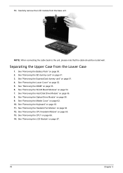
.... 8. Step 1~3 Size (Quantity) M2 x L4 (3) Color Black 20. See "Removing the WLAN Board Modules" on page 50. 2. See "Removing the Battery Pack" on page 54. 7. Gently remove the upper case from the top panel. See "Removing the Keyboard" on page 58. 9. 19. Chapter 3 73 See "Removing the Optical Drive Module" on page 63. Torque 3.0 kgf-cm...
.... 8. Step 1~3 Size (Quantity) M2 x L4 (3) Color Black 20. See "Removing the WLAN Board Modules" on page 50. 2. See "Removing the Battery Pack" on page 54. 7. Gently remove the upper case from the top panel. See "Removing the Keyboard" on page 58. 9. 19. Chapter 3 73 See "Removing the Optical Drive Module" on page 63. Torque 3.0 kgf-cm...
Aspire 5235 / 5535 Service Guide
Page 87
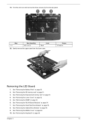
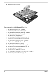
... WLAN Board Modules" on page 62. 10. See "Removing the Middle Cover" on page 54. 7. Remove the LED board from the upper cover. See "Removing the Keyboard" on page 51. 4. See "Removing the ExpressCard dummy card" on page 63. See "Removing the Lower Cover" on page 56. 8. See "Removing the Hard Disk Drive Module" on page 52...
... WLAN Board Modules" on page 62. 10. See "Removing the Middle Cover" on page 54. 7. Remove the LED board from the upper cover. See "Removing the Keyboard" on page 51. 4. See "Removing the ExpressCard dummy card" on page 63. See "Removing the Lower Cover" on page 56. 8. See "Removing the Hard Disk Drive Module" on page 52...
Aspire 5235 / 5535 Service Guide
Page 89
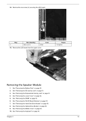
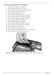
... the speaker cable from the upper case. Remove the speaker module from the latches. 19. Removing the Touchpad Module 1. See "Removing the Middle Cover" on page 65. See "Removing the Heatsink Fan Module" on page 63. 11. Chapter 3 77 See "Removing the Keyboard" on page 64. 12. 18. See "Removing the Battery Pack" on page 54. 7. See...
... the speaker cable from the upper case. Remove the speaker module from the latches. 19. Removing the Touchpad Module 1. See "Removing the Middle Cover" on page 65. See "Removing the Heatsink Fan Module" on page 63. 11. Chapter 3 77 See "Removing the Keyboard" on page 64. 12. 18. See "Removing the Battery Pack" on page 54. 7. See...
Aspire 5235 / 5535 Service Guide
Page 92
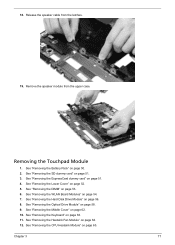
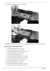
..." on page 54. 7. See "Removing the WLAN Board Modules" on page 65. 80 Chapter 3 See "Removing the Middle Cover" on page 64. 12. See "Removing the Heatsink Fan Module" on page 62. 10. See "Removing the DIMM" on page 58. 9. See "Removing the Optical Drive Module" on page ... only remove the touchpad board if it is defective. See "Removing the Lower Cover" on page 51. 3. Removing the Modem Board 1. Carefully pry loose and remove the touch pad board. See "Removing the SD dummy card" on page 52. 5. See "Removing the Keyboard" on page 56. 8. 20. See "Removing the ...
..." on page 54. 7. See "Removing the WLAN Board Modules" on page 65. 80 Chapter 3 See "Removing the Middle Cover" on page 64. 12. See "Removing the Heatsink Fan Module" on page 62. 10. See "Removing the DIMM" on page 58. 9. See "Removing the Optical Drive Module" on page ... only remove the touchpad board if it is defective. See "Removing the Lower Cover" on page 51. 3. Removing the Modem Board 1. Carefully pry loose and remove the touch pad board. See "Removing the SD dummy card" on page 52. 5. See "Removing the Keyboard" on page 56. 8. 20. See "Removing the ...
Aspire 5235 / 5535 Service Guide
Page 94
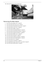
... the Lower Case" on page 80. 82 Chapter 3 Removing the Main Board 1. See "Removing the Optical Drive Module" on page 64. 12. See "Removing the Heatsink Fan Module" on page 58. 9. See "Removing the Keyboard" on page 52. 5. See "Removing the Lower Cover" on page 63. 11. See "Removing the WLAN Board Modules" on page 56. 8. See...
... the Lower Case" on page 80. 82 Chapter 3 Removing the Main Board 1. See "Removing the Optical Drive Module" on page 64. 12. See "Removing the Heatsink Fan Module" on page 58. 9. See "Removing the Keyboard" on page 52. 5. See "Removing the Lower Cover" on page 63. 11. See "Removing the WLAN Board Modules" on page 56. 8. See...
Aspire 5235 / 5535 Service Guide
Page 96
... Battery Pack" on page 63. 11. See "Removing the Keyboard" on page 50. 2. See "Removing the LCD Module" on page 51. 3. See "Removing the SD dummy card" on page 67. 15. See "Removing the Heatsink Fan Module" on page 62. 10. See "Removing the Middle Cover" on page 64. 12. See "Separating the Upper Case from...
... Battery Pack" on page 63. 11. See "Removing the Keyboard" on page 50. 2. See "Removing the LCD Module" on page 51. 3. See "Removing the SD dummy card" on page 67. 15. See "Removing the Heatsink Fan Module" on page 62. 10. See "Removing the Middle Cover" on page 64. 12. See "Separating the Upper Case from...
Aspire 5235 / 5535 Service Guide
Page 98
...page 54. 7. See "Removing the WLAN Board Modules" on page 56. 8. See "Removing the LCD Module" on page 52. 5. See "Removing the Lower Cover" on page 67. 15. See "Removing the CPU" on page 63. 11. See "Removing the Keyboard" on page 66. 14. See "Removing the CPU Heatsink Module" on... page 50. 2. See "Removing the Battery Pack" on page...
...page 54. 7. See "Removing the WLAN Board Modules" on page 56. 8. See "Removing the LCD Module" on page 52. 5. See "Removing the Lower Cover" on page 67. 15. See "Removing the CPU" on page 63. 11. See "Removing the Keyboard" on page 66. 14. See "Removing the CPU Heatsink Module" on... page 50. 2. See "Removing the Battery Pack" on page...
Aspire 5235 / 5535 Service Guide
Page 110
... with the internal diskette drive, reconnect the diskette connector on the System board. If the error still remains: 1. Keyboard or Auxiliary Input Device Check Remove the external keyboard if the internal keyboard is correct, run the Keyboard Test. Reconnect the external diskette drive/DVD-ROM module. 2. Do the following to isolate the problem to fail...
... with the internal diskette drive, reconnect the diskette connector on the System board. If the error still remains: 1. Keyboard or Auxiliary Input Device Check Remove the external keyboard if the internal keyboard is correct, run the Keyboard Test. Reconnect the external diskette drive/DVD-ROM module. 2. Do the following to isolate the problem to fail...
Aspire 5235 / 5535 Service Guide
Page 111
.... 2. Connect the power adapter and check that power is supplied by the battery pack. then check that power is fully installed into the connector. q External keyboard If any of the following list: q "Check the Power Adapter" on page 100 q "Check the Battery Pack" on page 101 Chapter 4 99 Power System Check... system operations, show error messages on the computer using each of these devices do not work, reconnect the cable connector and repeat the failing operation. Remove the battery pack. 2.
.... 2. Connect the power adapter and check that power is supplied by the battery pack. then check that power is fully installed into the connector. q External keyboard If any of the following list: q "Check the Power Adapter" on page 100 q "Check the Battery Pack" on page 101 Chapter 4 99 Power System Check... system operations, show error messages on the computer using each of these devices do not work, reconnect the cable connector and repeat the failing operation. Remove the battery pack. 2.
Aspire 5235 / 5535 Service Guide
Page 125
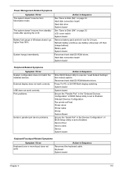
... go higher than 90%. USB does not work correctly Print problems. Serial or parallel port device problems. Action in Sequence Reconnect the keyboard cable. Keyboard System board Chapter 4 113 Press Fn+F5, LCD/CRT/Both display switching System board System board Ensure the "Parallel Port" in ... (S4)" on page 33. Hard disk connection board Hard disk drive System board See "Save to Enabled. LCD cover switch System board Remove battery pack and let it cool for 2 hours. Hard disk connection board System board Peripheral-Related Symptoms Symptom / Error System configuration does...
... go higher than 90%. USB does not work correctly Print problems. Serial or parallel port device problems. Action in Sequence Reconnect the keyboard cable. Keyboard System board Chapter 4 113 Press Fn+F5, LCD/CRT/Both display switching System board System board Ensure the "Parallel Port" in ... (S4)" on page 33. Hard disk connection board Hard disk drive System board See "Save to Enabled. LCD cover switch System board Remove battery pack and let it cool for 2 hours. Hard disk connection board System board Peripheral-Related Symptoms Symptom / Error System configuration does...


