Acer Aspire 5534 Notebook Series Start Guide
Page 5
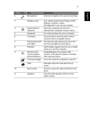
Indicates the status of wireless button/indicator LAN communication. Touchpad toggle Turns the internal touchpad on and off . HDD Indicates when the hard disk drive is active. 10 Eject button Presses to eject ...Description Internal microphone for sound recording. 3 Display screen Also called Liquid-Crystal Display (LCD), displays computer output (Configuration may vary by models). 4 Power button / Turns the computer on and off . / indicator Indicates the computer's power status. 5 Keyboard For entering data into your computer. 6 Touchpad Touch-sensitive pointing device ...
Indicates the status of wireless button/indicator LAN communication. Touchpad toggle Turns the internal touchpad on and off . HDD Indicates when the hard disk drive is active. 10 Eject button Presses to eject ...Description Internal microphone for sound recording. 3 Display screen Also called Liquid-Crystal Display (LCD), displays computer output (Configuration may vary by models). 4 Power button / Turns the computer on and off . / indicator Indicates the computer's power status. 5 Keyboard For entering data into your computer. 6 Touchpad Touch-sensitive pointing device ...
Acer Aspire 5534 Notebook Series Start Guide
Page 6
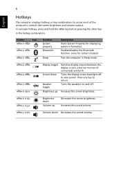
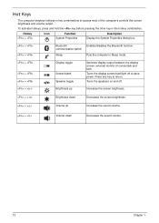
... Sleep mode. + + + + < > Display toggle Screen blank Speaker toggle Switches display output between the display screen, external monitor (if connected) and both. Turns the speakers on and off to save power. Turns the display screen backlight off . Press any key to access most of the computer's controls like screen brightness and volume output...
... Sleep mode. + + + + < > Display toggle Screen blank Speaker toggle Switches display output between the display screen, external monitor (if connected) and both. Turns the speakers on and off to save power. Turns the display screen backlight off . Press any key to access most of the computer's controls like screen brightness and volume output...
Acer Aspire 5534 Notebook Series Start Guide
Page 8
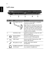
...: Wrap the computer security lock cable around an immovable object such as a table or handle of a locked drawer. Insert the lock into the notch and turn the key to USB 2.0 devices (e.g., USB mouse, USB camera). USB 2.0 port Microphone-in jack Connect to secure the lock. Headphones/speaker/ Connects to stay cool...
...: Wrap the computer security lock cable around an immovable object such as a table or handle of a locked drawer. Insert the lock into the notch and turn the key to USB 2.0 devices (e.g., USB mouse, USB camera). USB 2.0 port Microphone-in jack Connect to secure the lock. Headphones/speaker/ Connects to stay cool...
Acer Aspire 5534 Notebook Series Start Guide
Page 9
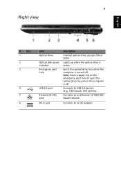
accepts CDs or DVDs. Lights up when the optical drive is turned off . Connects to an AC adapter. 9 Right view English # Icon 1 2 3 4 5 6 Item Optical drive Optical disk access indicator Emergency eject hole USB 2.0 port Ethernet (RJ-45) port DC-in jack Description Internal optical drive; Connects to USB 2.0 devices (e.g., USB mouse, USB camera). Ejects the optical drive tray when the computer is active. Connects to eject the optical drive tray when the computer is off . Note: Insert a paper clip to the emergency eject hole to an Ethernet 10/100/1000based network.
accepts CDs or DVDs. Lights up when the optical drive is turned off . Connects to an AC adapter. 9 Right view English # Icon 1 2 3 4 5 6 Item Optical drive Optical disk access indicator Emergency eject hole USB 2.0 port Ethernet (RJ-45) port DC-in jack Description Internal optical drive; Connects to USB 2.0 devices (e.g., USB mouse, USB camera). Ejects the optical drive tray when the computer is active. Connects to eject the optical drive tray when the computer is off . Note: Insert a paper clip to the emergency eject hole to an Ethernet 10/100/1000based network.
Aspire 5534 Service Guide
Page 14
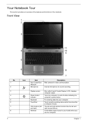
Display screen Power button/ indicator Keyboard TouchPad Click buttons (left and right mouse buttons. Turns the computer on and off while indicating the computer's power status. Comfortable support area for your computer. The left and right buttons ...which functions like the left and right) Palmrest Also called Liquid-Crystal Display (LCD), displays computer output. Front View No. 1 2 3 4 5 6 7 8 4 Icon Item Acer Crystal Eye Webcam Microphone Description Web camera for sound recording. Your Notebook Tour This section provides an overview of the features and functions of the...
Display screen Power button/ indicator Keyboard TouchPad Click buttons (left and right mouse buttons. Turns the computer on and off while indicating the computer's power status. Comfortable support area for your computer. The left and right buttons ...which functions like the left and right) Palmrest Also called Liquid-Crystal Display (LCD), displays computer output. Front View No. 1 2 3 4 5 6 7 8 4 Icon Item Acer Crystal Eye Webcam Microphone Description Web camera for sound recording. Your Notebook Tour This section provides an overview of the features and functions of the...

Aspire 5534 Service Guide
Page 15
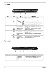
... when the hard disk drive is charging. 2. Chapter 1 5 No. 1 2 Icon Item Battery Indicator 5-in AC mode. Only one card can operate at any given time. Turns the internal touchpad on and off. Charging: The light shows amber when the battery is active. Left and right speakers deliver stereo audio output. Fully...
... when the hard disk drive is charging. 2. Chapter 1 5 No. 1 2 Icon Item Battery Indicator 5-in AC mode. Only one card can operate at any given time. Turns the internal touchpad on and off. Charging: The light shows amber when the battery is active. Left and right speakers deliver stereo audio output. Fully...
Aspire 5534 Service Guide
Page 16
... lock. accepts CDs or DVDs. No. 1 2 Icon Item Optical drive Optical disk access indicator Description Internal optical drive; Insert the lock into the notch and turn the key to audio line-out devices (e.g., speakers, headphones). Lights up when the optical drive is active. 6 Chapter 1 Connect to a display device (e.g., external monitor, LCD...
... lock. accepts CDs or DVDs. No. 1 2 Icon Item Optical drive Optical disk access indicator Description Internal optical drive; Insert the lock into the notch and turn the key to audio line-out devices (e.g., speakers, headphones). Lights up when the optical drive is active. 6 Chapter 1 Connect to a display device (e.g., external monitor, LCD...

Aspire 5534 Service Guide
Page 17
... to stay cool, even after prolonged use. No. 1 2 3 4 5 6 Icon Item Battery bay Battery lock Description Houses the computer's battery pack. Note: The battery shown is turned off . Chapter 1 7 based network. Memory compartment Hard Disk Bay Ventilation slots and/or cooling fan Battery Release Latch Houses the computer's main memory. Houses the...
... to stay cool, even after prolonged use. No. 1 2 3 4 5 6 Icon Item Battery bay Battery lock Description Houses the computer's battery pack. Note: The battery shown is turned off . Chapter 1 7 based network. Memory compartment Hard Disk Bay Ventilation slots and/or cooling fan Battery Release Latch Houses the computer's main memory. Houses the...
Aspire 5534 Service Guide
Page 22
... toggle Switches display output between the display screen, external monitor (if connected) and both. Hot Keys The computer employs hotkeys or key combinations to return. Turns the display screen backlight off . + < > Brightness up Increases the screen brightness. + < > Brightness down Decreases the screen brightness. + < > Volume up Increases the sound volume. + < > Volume down...
... toggle Switches display output between the display screen, external monitor (if connected) and both. Hot Keys The computer employs hotkeys or key combinations to return. Turns the display screen backlight off . + < > Brightness up Increases the screen brightness. + < > Brightness down Decreases the screen brightness. + < > Volume up Increases the sound volume. + < > Volume down...
Aspire 5534 Service Guide
Page 54
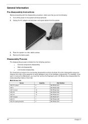
... succeeding disassembly sections illustrate the entire disassembly sequence. Disassembly Process The disassembly process is divided into the following : 1. Unplug the AC adapter and all peripherals. 2. Turn off the power to any of the sequence to avoid damage to the system and all power and signal cables from the system. 3. General Information...
... succeeding disassembly sections illustrate the entire disassembly sequence. Disassembly Process The disassembly process is divided into the following : 1. Unplug the AC adapter and all peripherals. 2. Turn off the power to any of the sequence to avoid damage to the system and all power and signal cables from the system. 3. General Information...

Aspire 5534 Service Guide
Page 55
External Modules Disassembly Flowchart Turn off system and peripherals power Disconnect power and signal cables from system Remove Battery Remove Dummy Card Remove Lower Covers Remove DIMMs Remove WLAN Remove ...
External Modules Disassembly Flowchart Turn off system and peripherals power Disconnect power and signal cables from system Remove Battery Remove Dummy Card Remove Lower Covers Remove DIMMs Remove WLAN Remove ...

Aspire 5534 Service Guide
Page 56
Slide and hold the battery release latch to the unlock position. 3. Removing the Battery Pack 1. Slide the battery lock/unlock latch to the release position (1), then slide out the battery pack from the main unit (2). 2 1 46 Chapter 3 Turn the computer over. 2.
Slide and hold the battery release latch to the unlock position. 3. Removing the Battery Pack 1. Slide the battery lock/unlock latch to the release position (1), then slide out the battery pack from the main unit (2). 2 1 46 Chapter 3 Turn the computer over. 2.
Aspire 5534 Service Guide
Page 70
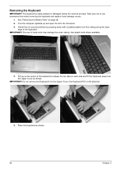
... may damage the outer casing. Use plastic tools where available. 4. Pull up and open the lid to the full extent. 3. Place the keyboard as shown. Turn the computer rightside up on the center of the keyboard to use of the keyboard. IMPORTANT: The use excessive force when removing the keyboard and...
... may damage the outer casing. Use plastic tools where available. 4. Pull up and open the lid to the full extent. 3. Place the keyboard as shown. Turn the computer rightside up on the center of the keyboard to use of the keyboard. IMPORTANT: The use excessive force when removing the keyboard and...

Aspire 5534 Service Guide
Page 72
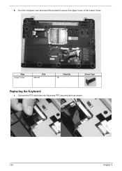
Remove all external modules. See "External Modules Disassembly Flowchart" on page 45. 2. Disconnect the Speaker Cable as shown. 62 Chapter 3 Removing the Upper Cover 1. Remove the screws securing the Upper Cover to the Lower Cover. Step Upper Cover Size M2.5*8 Quantity 18 Screw Type 3. Turn the computer over and disconnect the following cables from the Mainboard: a.
Remove all external modules. See "External Modules Disassembly Flowchart" on page 45. 2. Disconnect the Speaker Cable as shown. 62 Chapter 3 Removing the Upper Cover 1. Remove the screws securing the Upper Cover to the Lower Cover. Step Upper Cover Size M2.5*8 Quantity 18 Screw Type 3. Turn the computer over and disconnect the following cables from the Mainboard: a.

Aspire 5534 Service Guide
Page 106
Carefully lift the adhesive tape securing the LVDS cable connector to the LCD Panel. 4. Removing the FPC Cable 1. Turn the LCD panel over on page 95. 2. Lift the camera cable to detach the adhesive securing the cable to the LCD Panel. 5. Hold the adhesive tape clear of the LCD Panel. 96 Chapter 3 See "Removing the LCD Panel" on a clean surface. 3.
Carefully lift the adhesive tape securing the LVDS cable connector to the LCD Panel. 4. Removing the FPC Cable 1. Turn the LCD panel over on page 95. 2. Lift the camera cable to detach the adhesive securing the cable to the LCD Panel. 5. Hold the adhesive tape clear of the LCD Panel. 96 Chapter 3 See "Removing the LCD Panel" on a clean surface. 3.

Aspire 5534 Service Guide
Page 143
Insert the seven securing screws into the Upper Cover. Step Upper Cover Size M2.5*6 Quantity 7 Screw Type 4. 3. Turn the computer over and connect the following cables to the Mainboard: Chapter 3 133
Insert the seven securing screws into the Upper Cover. Step Upper Cover Size M2.5*6 Quantity 7 Screw Type 4. 3. Turn the computer over and connect the following cables to the Mainboard: Chapter 3 133
Aspire 5534 Service Guide
Page 146
5. Turn the computer over and insert the screws to secure the Upper Cover to the Lower Cover. Connect the FFC and close the Keyboard FFC securing latch as shown. 136 Chapter 3 Step Upper Cover Size M2.5*8 Quantity 18 Screw Type Replacing the Keyboard 1.
5. Turn the computer over and insert the screws to secure the Upper Cover to the Lower Cover. Connect the FFC and close the Keyboard FFC securing latch as shown. 136 Chapter 3 Step Upper Cover Size M2.5*8 Quantity 18 Screw Type Replacing the Keyboard 1.
Aspire 5534 Service Guide
Page 169
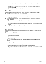
... and clean the failed disc. 2. a. Ensure that the entry is detected in "Hardware Specifications and Configurations" on the drive, motherboard, and cable connections. Turn off the power and remove the cover to inspect the connections to Start´ Control Panel´ System and Maintenance´ System´ Device Manager... a. Check for bent or broken pins on page 18. 3. Navigate to the ODD. Test the drive using other ATA Devices shown if applicable. Turn off the power and remove the cover to inspect the connections to enter the BIOS Utility. 2.
... and clean the failed disc. 2. a. Ensure that the entry is detected in "Hardware Specifications and Configurations" on the drive, motherboard, and cable connections. Turn off the power and remove the cover to inspect the connections to Start´ Control Panel´ System and Maintenance´ System´ Device Manager... a. Check for bent or broken pins on page 18. 3. Navigate to the ODD. Test the drive using other ATA Devices shown if applicable. Turn off the power and remove the cover to inspect the connections to enter the BIOS Utility. 2.


