Acer Aspire 5534 Notebook Series Start Guide
Page 5
... may vary by models). 4 Power button / Turns the computer on and off . / indicator Indicates the computer's power status. 5 Keyboard For entering data into your computer. 6 Touchpad Touch-sensitive pointing device which functions like a computer mouse. 7 Click buttons (left The left and right buttons function like and right) the left and right... drive is active. 10 Eject button Presses to eject the optical disk from the drive. 11 Speakers Left and right speakers deliver stereo audio output. Touchpad toggle Turns the internal touchpad on and off .
... may vary by models). 4 Power button / Turns the computer on and off . / indicator Indicates the computer's power status. 5 Keyboard For entering data into your computer. 6 Touchpad Touch-sensitive pointing device which functions like a computer mouse. 7 Click buttons (left The left and right buttons function like and right) the left and right... drive is active. 10 Eject button Presses to eject the optical disk from the drive. 11 Speakers Left and right speakers deliver stereo audio output. Touchpad toggle Turns the internal touchpad on and off .
Acer Aspire 5534 Notebook Series Start Guide
Page 11
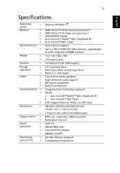
... user, supervisor, HDD passwords Kensington lock slot ACPI 3.0 48.8 W 4400 mAh 3-pin 65 W AC adapter ENERGY STAR®* 99-/100-/103-key keyboard Touchpad pointing device 11 English Specifications Operating • system Platform • • • • • System memory • • Display •... AMD Athlon™ 64 X2 dual-core processor* AMD Athlon™ 64 single-core processor* AMD M780G Chipset Acer InviLink™ Nplify™ 802.11b/g/Draft-N* Acer InviLink™ 802.11b/g* Dual-channel support Up to 2 GB of DDR2 667 MHz memory, upgradeable to 4...
... user, supervisor, HDD passwords Kensington lock slot ACPI 3.0 48.8 W 4400 mAh 3-pin 65 W AC adapter ENERGY STAR®* 99-/100-/103-key keyboard Touchpad pointing device 11 English Specifications Operating • system Platform • • • • • System memory • • Display •... AMD Athlon™ 64 X2 dual-core processor* AMD Athlon™ 64 single-core processor* AMD M780G Chipset Acer InviLink™ Nplify™ 802.11b/g/Draft-N* Acer InviLink™ 802.11b/g* Dual-channel support Up to 2 GB of DDR2 667 MHz memory, upgradeable to 4...
Aspire 5534 Service Guide
Page 7
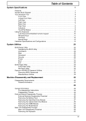
... of Contents System Specifications 1 Features 1 System Block Diagram 3 Your Notebook Tour 4 Front View 4 Closed Front View 5 Left View 6 Right View 6 Base View 7 Rear View 8 Indicators 8 TouchPad Basics 9 Using the Keyboard 10 Lock Keys and embedded numeric keypad 10 Windows Keys 11 Hot Keys 12 Special Keys 13 Hardware Specifications and Configurations...
... of Contents System Specifications 1 Features 1 System Block Diagram 3 Your Notebook Tour 4 Front View 4 Closed Front View 5 Left View 6 Right View 6 Base View 7 Rear View 8 Indicators 8 TouchPad Basics 9 Using the Keyboard 10 Lock Keys and embedded numeric keypad 10 Windows Keys 11 Hot Keys 12 Special Keys 13 Hardware Specifications and Configurations...
Aspire 5534 Service Guide
Page 8
Table of Contents Removing the Upper Cover 62 Removing the Button Board 66 Removing the Touchpad Bracket 68 Removing the Power Board 70 Removing the Speaker Modules 72 Removing the Media Board 74 Removing the Bluetooth Module 76 Removing the I/O ...the I/O Board 121 Replacing the Bluetooth Module 123 Replacing the Media Board 124 Replacing the Speaker Modules 125 Replacing the Power Board 127 Replacing the Touchpad Bracket 128 Replacing the Button Board 130 Replacing the Upper Cover 131 Replacing the Keyboard 136 External Module Reassembly Process 138 Replacing the WLAN Board...
Table of Contents Removing the Upper Cover 62 Removing the Button Board 66 Removing the Touchpad Bracket 68 Removing the Power Board 70 Removing the Speaker Modules 72 Removing the Media Board 74 Removing the Bluetooth Module 76 Removing the I/O ...the I/O Board 121 Replacing the Bluetooth Module 123 Replacing the Media Board 124 Replacing the Speaker Modules 125 Replacing the Power Board 127 Replacing the Touchpad Bracket 128 Replacing the Button Board 130 Replacing the Upper Cover 131 Replacing the Keyboard 136 External Module Reassembly Process 138 Replacing the WLAN Board...
Aspire 5534 Service Guide
Page 9
...Power On Issue 149 No Display Issue 150 Random Loss of BIOS Settings 151 LCD Failure 152 Built-In Keyboard Failure 152 Touchpad Failure 153 Internal Speaker Failure 153 Internal Microphone Failure 155 HDD Not Operating Correctly 156 ODD Failure 157 USB Failure (Right ... 175 Clearing Password Check 175 BIOS Recovery by Crisis Disk 176 FRU (Field Replaceable Unit) List 177 Aspire 5534 Exploded Diagrams 178 Main Assembly 178 LCD Assembly 179 Aspire 5534 FRU List 180 Screw List 186 Model Definition and Configuration 188 Test Compatible Components 206 Windows 7 Environment ...
...Power On Issue 149 No Display Issue 150 Random Loss of BIOS Settings 151 LCD Failure 152 Built-In Keyboard Failure 152 Touchpad Failure 153 Internal Speaker Failure 153 Internal Microphone Failure 155 HDD Not Operating Correctly 156 ODD Failure 157 USB Failure (Right ... 175 Clearing Password Check 175 BIOS Recovery by Crisis Disk 176 FRU (Field Replaceable Unit) List 177 Aspire 5534 Exploded Diagrams 178 Main Assembly 178 LCD Assembly 179 Aspire 5534 FRU List 180 Screw List 186 Model Definition and Configuration 188 Test Compatible Components 206 Windows 7 Environment ...

Aspire 5534 Service Guide
Page 12
...™ Nplify™ 802.11b/g/Draft-N* • Acer InviLink™ 802.11b/g* • LAN: Gigabit Ethernet; The exact configuration of the PC depends on -LAN ready Privacy control • BIOS user, supervisor, HDD ...; ACPI 3.0 • 48.8 W 4400 mAh • 3-pin 65 W AC adapter • ENERGY STAR®* Special keys and controls • 99-/100-/103-key keyboard • Touchpad pointing device I/O interface • Multi-in-1 card reader (SD™, MMC, MS, MS PRO, xD) • USB 2.0 port • External display (VGA) port • Headphones...
...™ Nplify™ 802.11b/g/Draft-N* • Acer InviLink™ 802.11b/g* • LAN: Gigabit Ethernet; The exact configuration of the PC depends on -LAN ready Privacy control • BIOS user, supervisor, HDD ...; ACPI 3.0 • 48.8 W 4400 mAh • 3-pin 65 W AC adapter • ENERGY STAR®* Special keys and controls • 99-/100-/103-key keyboard • Touchpad pointing device I/O interface • Multi-in-1 card reader (SD™, MMC, MS, MS PRO, xD) • USB 2.0 port • External display (VGA) port • Headphones...
Aspire 5534 Service Guide
Page 14
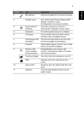
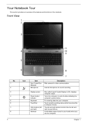
Front View No. 1 2 3 4 5 6 7 8 4 Icon Item Acer Crystal Eye Webcam Microphone Description Web camera for sound recording. Display screen Power button/ indicator Keyboard TouchPad Click buttons (left and right mouse buttons. Turns the computer on and off while indicating the computer's power status. Your Notebook Tour This section provides ...
Front View No. 1 2 3 4 5 6 7 8 4 Icon Item Acer Crystal Eye Webcam Microphone Description Web camera for sound recording. Display screen Power button/ indicator Keyboard TouchPad Click buttons (left and right mouse buttons. Turns the computer on and off while indicating the computer's power status. Your Notebook Tour This section provides ...

Aspire 5534 Service Guide
Page 15
.... Accepts Secure Digital (SD), MultiMediaCard (MMC), Memory Stick (MS), Memory Stick PRO (MS PRO), xDPicture Card (xD). No. 9 Icon Item Wireless LAN communication button/indicator Touchpad toggle Description Enables / disables the WLAN function. HDD 10 Eject button 11 Speakers Closed Front View Indicates when the hard disk drive is charging. 2. No...
.... Accepts Secure Digital (SD), MultiMediaCard (MMC), Memory Stick (MS), Memory Stick PRO (MS PRO), xDPicture Card (xD). No. 9 Icon Item Wireless LAN communication button/indicator Touchpad toggle Description Enables / disables the WLAN function. HDD 10 Eject button 11 Speakers Closed Front View Indicates when the hard disk drive is charging. 2. No...

Aspire 5534 Service Guide
Page 19
... Select Drag Access context menu Left Button (2) Quickly click twice. Click once. TouchPad Basics The following items show you how to use finger on the TouchPad to drag the cursor. Tapping on the TouchPad is sensitive to perform selection and execution functions. Click and hold, then use the... tap and drag the cursor. hence, the lighter the touch, the better the response. Right Button (3) Click once. and your finger on the TouchPad on a mouse. Tap once. Tap twice (at the same speed as double-clicking a mouse button); dry and clean. Tapping too hard will...
... Select Drag Access context menu Left Button (2) Quickly click twice. Click once. TouchPad Basics The following items show you how to use finger on the TouchPad to drag the cursor. Tapping on the TouchPad is sensitive to perform selection and execution functions. Click and hold, then use the... tap and drag the cursor. hence, the lighter the touch, the better the response. Right Button (3) Click once. and your finger on the TouchPad on a mouse. Tap once. Tap twice (at the same speed as double-clicking a mouse button); dry and clean. Tapping too hard will...
Aspire 5534 Service Guide
Page 68
... Remove CPU Fan Remove Power Board Remove Mainboard Remove Thermal Module Screw List Step Upper Cover Upper Cover Button Board TouchPad Bracket Power Board Speaker Module Media Board 58 Remove Touchpad Board Remove Touchpad Bracket Remove CPU Screw M2.5*8 M2.5*6 M2*3 M2*3 M2.5*3 M2.5*3 M2.5*3 Quantity 18 7 3 1 1 4 1 Part No. 86.PEA02.006 86...
... Remove CPU Fan Remove Power Board Remove Mainboard Remove Thermal Module Screw List Step Upper Cover Upper Cover Button Board TouchPad Bracket Power Board Speaker Module Media Board 58 Remove Touchpad Board Remove Touchpad Bracket Remove CPU Screw M2.5*8 M2.5*6 M2*3 M2*3 M2.5*3 M2.5*3 M2.5*3 Quantity 18 7 3 1 1 4 1 Part No. 86.PEA02.006 86...

Aspire 5534 Service Guide
Page 76
To replace the Button Board, replace the entire Upper Cover. 1. See "Removing the Upper Cover" on page 62. 2. Lift the securing latch and disconnect the single FFC connecting the Button Board to the Touchpad. 4. Detach the button board FFC from the adhesive securing it from the adhesive. 66 Chapter 3 Pull the Mainboard FFC through the opening in the upper cover and separate it in place. 5. Removing the Button Board IMPORTANT: The Touchpad Board cannot be removed individually. Remove the mylar sheet covering the Button Board. 3.
To replace the Button Board, replace the entire Upper Cover. 1. See "Removing the Upper Cover" on page 62. 2. Lift the securing latch and disconnect the single FFC connecting the Button Board to the Touchpad. 4. Detach the button board FFC from the adhesive securing it from the adhesive. 66 Chapter 3 Pull the Mainboard FFC through the opening in the upper cover and separate it in place. 5. Removing the Button Board IMPORTANT: The Touchpad Board cannot be removed individually. Remove the mylar sheet covering the Button Board. 3.

Aspire 5534 Service Guide
Page 78
Pull the bracket up from the slots in the upper cover. 68 Chapter 3 NOTE: It may be more readily removed. 4. Step TouchPad Bracket M2*3 Size Quantity 1 Screw Type 3. Slide the Touchpad Bracket out from under the securing tabs along the top edge. Removing the Touchpad Bracket 1. Remove the single screw securing the Touchpad Bracket to first push the securing tabs back so that the bracket may be necessary to use a tool to the Upper Cover. See "Removing the Button Board" on page 66. 2.
Pull the bracket up from the slots in the upper cover. 68 Chapter 3 NOTE: It may be more readily removed. 4. Step TouchPad Bracket M2*3 Size Quantity 1 Screw Type 3. Slide the Touchpad Bracket out from under the securing tabs along the top edge. Removing the Touchpad Bracket 1. Remove the single screw securing the Touchpad Bracket to first push the securing tabs back so that the bracket may be necessary to use a tool to the Upper Cover. See "Removing the Button Board" on page 66. 2.

Aspire 5534 Service Guide
Page 138
Insert the single screw to secure the Power Board to the Lower Cover. Step Power Board Size M2.5*3 Quantity 1 Replacing the Touchpad Bracket 1. Screw Type 128 Chapter 3 3. Slide the Touchpad Bracket into the slots in the upper cover.
Insert the single screw to secure the Power Board to the Lower Cover. Step Power Board Size M2.5*3 Quantity 1 Replacing the Touchpad Bracket 1. Screw Type 128 Chapter 3 3. Slide the Touchpad Bracket into the slots in the upper cover.

Aspire 5534 Service Guide
Page 139
Step TouchPad Bracket M2*3 Size Quantity 1 Screw Type Chapter 3 129 Push the bracket down until it is secured under the tabs along the top edge. 3. 2. Insert the single screw to secure the Touchpad Bracket to the Upper Cover.
Step TouchPad Bracket M2*3 Size Quantity 1 Screw Type Chapter 3 129 Push the bracket down until it is secured under the tabs along the top edge. 3. 2. Insert the single screw to secure the Touchpad Bracket to the Upper Cover.

Aspire 5534 Service Guide
Page 141
Place the Upper Cover on the assembly bottom edge first. Replacing the Upper Cover 1. Chapter 3 131 4. Replace the mylar sheet covering the Button Board. Connect the single FFC to the Touchpad and close the securing latch. 5.
Place the Upper Cover on the assembly bottom edge first. Replacing the Upper Cover 1. Chapter 3 131 4. Replace the mylar sheet covering the Button Board. Connect the single FFC to the Touchpad and close the securing latch. 5.
Aspire 5534 Service Guide
Page 158
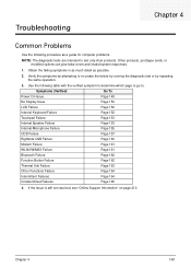
Symptoms (Verified) Go To Power On Issue Page 149 No Display Issue Page 150 LCD Failure Page 152 Internal Keyboard Failure Page 152 Touchpad Failure Page 153 Internal Speaker Failure Page 153 Internal Microphone Failure Page 155 ODD Failure Page 157 Rightside USB Failure Page 160 Modem Failure Page ... by attempting to . Obtain the failing symptoms in as much detail as a guide for computer problems. NOTE: The diagnostic tests are intended to test only Acer products.
Symptoms (Verified) Go To Power On Issue Page 149 No Display Issue Page 150 LCD Failure Page 152 Internal Keyboard Failure Page 152 Touchpad Failure Page 153 Internal Speaker Failure Page 153 Internal Microphone Failure Page 155 ODD Failure Page 157 Rightside USB Failure Page 160 Modem Failure Page ... by attempting to . Obtain the failing symptoms in as much detail as a guide for computer problems. NOTE: The diagnostic tests are intended to test only Acer products.

Aspire 5534 Service Guide
Page 163
Do not replace a non-defective FRUs: 153 Chapter 4 Touchpad Failure If the Touchpad doesn't work, perform the following actions one at a time to correct the problem. Do not replace a non-defective FRUs: Internal Speaker Failure If the internal Speakers fail, perform the following actions one at a time to correct the problem.
Do not replace a non-defective FRUs: 153 Chapter 4 Touchpad Failure If the Touchpad doesn't work, perform the following actions one at a time to correct the problem. Do not replace a non-defective FRUs: Internal Speaker Failure If the internal Speakers fail, perform the following actions one at a time to correct the problem.
Aspire 5534 Service Guide
Page 222
... Modules Removing 72 speakers hotkey 12 System Block Diagram 3 T Test Compatible Components 206 Thermal Module Removing 88 Replacing 114 Thermal Unit Failure 163 Top 173 Touchpad Bracket Removing 68 Replacing 128
... Modules Removing 72 speakers hotkey 12 System Block Diagram 3 T Test Compatible Components 206 Thermal Module Removing 88 Replacing 114 Thermal Unit Failure 163 Top 173 Touchpad Bracket Removing 68 Replacing 128

Aspire 5534 Service Guide
Page 223
Touchpad Failure 153 Troubleshooting Built-in KB Failure 152 Internal Microphone 155 Internal Speakers 153 LCD Failure 152 No Display 150 Other Failures 164 Thermal Unit 163 Touchpad 153 USB 160 WLAN 161 U Undetermined Problems 165 Upper Cover Removing 62 Replacing 131 USB Failure (Rightside) 160 utility BIOS 23-34 V volume hotkeys 12 W Windows 2000 Environment Test 206 Wireless Function Failure 161 WLAN Antennas Removing 101 Replacing 103 WLAN Board Removing 56 Replacing 138 213
Touchpad Failure 153 Troubleshooting Built-in KB Failure 152 Internal Microphone 155 Internal Speakers 153 LCD Failure 152 No Display 150 Other Failures 164 Thermal Unit 163 Touchpad 153 USB 160 WLAN 161 U Undetermined Problems 165 Upper Cover Removing 62 Replacing 131 USB Failure (Rightside) 160 utility BIOS 23-34 V volume hotkeys 12 W Windows 2000 Environment Test 206 Wireless Function Failure 161 WLAN Antennas Removing 101 Replacing 103 WLAN Board Removing 56 Replacing 138 213


