Aspire 5534 Service Guide
Page 8
... Procedure 103 Replacing the Antennas 103 Replacing the Microphone 104 Replacing the LCD Brackets 105 Replacing the FPC Cable 107 Replacing the LCD Panel 108 Replacing the Camera Board 109 Replacing the LCD Bezel 109 Main Unit Reassembly Process 112 Replacing the LCD Module 112 Replacing the CPU 113 Replacing the Thermal Module 114 Replacing the Fan 116 Replacing the Mainboard 118 Replacing the I/O Board 121 Replacing the...
... Procedure 103 Replacing the Antennas 103 Replacing the Microphone 104 Replacing the LCD Brackets 105 Replacing the FPC Cable 107 Replacing the LCD Panel 108 Replacing the Camera Board 109 Replacing the LCD Bezel 109 Main Unit Reassembly Process 112 Replacing the LCD Module 112 Replacing the CPU 113 Replacing the Thermal Module 114 Replacing the Fan 116 Replacing the Mainboard 118 Replacing the I/O Board 121 Replacing the...
Aspire 5534 Service Guide
Page 9
... Contents Troubleshooting 148 Common Problems 148 Power On Issue 149 No Display Issue 150 Random Loss of BIOS Settings 151 LCD Failure 152 Built-In Keyboard Failure 152 Touchpad Failure 153 Internal Speaker Failure 153 Internal Microphone Failure 155 HDD Not... and BIOS Recovery 175 Clearing Password Check 175 BIOS Recovery by Crisis Disk 176 FRU (Field Replaceable Unit) List 177 Aspire 5534 Exploded Diagrams 178 Main Assembly 178 LCD Assembly 179 Aspire 5534 FRU List 180 Screw List 186 Model Definition and Configuration 188 Test Compatible Components 206 Windows 7...
... Contents Troubleshooting 148 Common Problems 148 Power On Issue 149 No Display Issue 150 Random Loss of BIOS Settings 151 LCD Failure 152 Built-In Keyboard Failure 152 Touchpad Failure 153 Internal Speaker Failure 153 Internal Microphone Failure 155 HDD Not... and BIOS Recovery 175 Clearing Password Check 175 BIOS Recovery by Crisis Disk 176 FRU (Field Replaceable Unit) List 177 Aspire 5534 Exploded Diagrams 178 Main Assembly 178 LCD Assembly 179 Aspire 5534 FRU List 180 Screw List 186 Model Definition and Configuration 188 Test Compatible Components 206 Windows 7...
Aspire 5534 Service Guide
Page 68
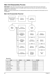
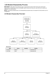
... components, ensure all available cable channels and clips are used and that the cables are replaced in the disassembly procedures may not represent the actual model. NOTE: The product previews seen in the same position. Main Unit Disassembly Flowchart ...Remove Upper Cover Upper Cover Remove Function Board Lower Cover Remove Right Speaker Module Remove Left Speaker Module Remove I/O Board Remove Power Socket Remove LCD Module Remove CPU Fan Remove Power Board Remove Mainboard Remove Thermal Module Screw List Step Upper Cover Upper Cover Button Board TouchPad Bracket Power Board...
... components, ensure all available cable channels and clips are used and that the cables are replaced in the disassembly procedures may not represent the actual model. NOTE: The product previews seen in the same position. Main Unit Disassembly Flowchart ...Remove Upper Cover Upper Cover Remove Function Board Lower Cover Remove Right Speaker Module Remove Left Speaker Module Remove I/O Board Remove Power Socket Remove LCD Module Remove CPU Fan Remove Power Board Remove Mainboard Remove Thermal Module Screw List Step Upper Cover Upper Cover Button Board TouchPad Bracket Power Board...
Aspire 5534 Service Guide
Page 100
... Remove LCD Bezel Remove LCD Panel Remove Camera Module Remove LCD Brackets Remove LCD FPC Cable Remove Antennas Remove Microphone Screw List Step LCD Bezel LCD Panel Screw M2.5*4 M2*3 Quantity 4 4 Part No. 86.PEA02.003 86.PEA02.002 90 Chapter 3 During the removal and replacement of ...components, ensure all available cable channels and clips are used and that the cables are replaced in the disassembly procedures may not represent the actual model. LCD Module Disassembly Process IMPORTANT: Cable paths and positioning...
... Remove LCD Bezel Remove LCD Panel Remove Camera Module Remove LCD Brackets Remove LCD FPC Cable Remove Antennas Remove Microphone Screw List Step LCD Bezel LCD Panel Screw M2.5*4 M2*3 Quantity 4 4 Part No. 86.PEA02.003 86.PEA02.002 90 Chapter 3 During the removal and replacement of ...components, ensure all available cable channels and clips are used and that the cables are replaced in the disassembly procedures may not represent the actual model. LCD Module Disassembly Process IMPORTANT: Cable paths and positioning...
Aspire 5534 Service Guide
Page 113
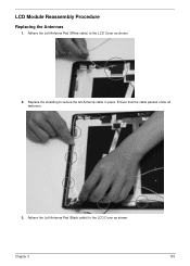
Ensure that the cable passes under all fasteners. 3. Chapter 3 103 Replace the shielding to the LCD Cover as shown. LCD Module Reassembly Procedure Replacing the Antennas 1. Adhere the Left Antenna Pad (White cable) to secure the left Antenna cable in place. Adhere the Left Antenna Pad (Black cable) to the LCD Cover as shown. 2.
Ensure that the cable passes under all fasteners. 3. Chapter 3 103 Replace the shielding to the LCD Cover as shown. LCD Module Reassembly Procedure Replacing the Antennas 1. Adhere the Left Antenna Pad (White cable) to secure the left Antenna cable in place. Adhere the Left Antenna Pad (Black cable) to the LCD Cover as shown. 2.
Aspire 5534 Service Guide
Page 114
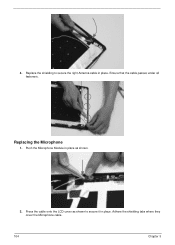
Adhere the shielding tabs where they cover the Microphone cable. 104 Chapter 3 Replacing the Microphone 1. Replace the shielding to secure it in place. Press the cable onto the LCD cover as shown. 2. Push the Microphone Module in place as shown to secure the right Antenna cable in place. Ensure that the cable passes under all fasteners. 4.
Adhere the shielding tabs where they cover the Microphone cable. 104 Chapter 3 Replacing the Microphone 1. Replace the shielding to secure it in place. Press the cable onto the LCD cover as shown. 2. Push the Microphone Module in place as shown to secure the right Antenna cable in place. Ensure that the cable passes under all fasteners. 4.
Aspire 5534 Service Guide
Page 115
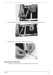
Lift the antenna cable and slide the left LCD Bracket under the shielding tabs along the bottom edge of the LCD Cover. 4. Secure the Microphone cable under the antenna cable. Apply tape to secure the Microphone cable to the antenna cables. 3. Replacing the LCD Brackets 1. Chapter 3 105
Lift the antenna cable and slide the left LCD Bracket under the shielding tabs along the bottom edge of the LCD Cover. 4. Secure the Microphone cable under the antenna cable. Apply tape to secure the Microphone cable to the antenna cables. 3. Replacing the LCD Brackets 1. Chapter 3 105

Aspire 5534 Service Guide
Page 117
Connect the LCD cable as shown. 2. Chapter 3 107 Adhere the camera cable to the LCD Panel. 3. Replacing the FPC Cable 1. Adhere the clear adhesive tape to the LCD Panel.
Connect the LCD cable as shown. 2. Chapter 3 107 Adhere the camera cable to the LCD Panel. 3. Replacing the FPC Cable 1. Adhere the clear adhesive tape to the LCD Panel.

Aspire 5534 Service Guide
Page 118
Step LCD Panel M2*3 Size 108 Quantity 4 Screw Type Chapter 3 Replacing the LCD Panel 1. Place the LCD Panel into of the LCD Cover back edge first, aligning the pins with the holes in the mounting tabs. 2. Insert the four screws to secure the LCD Panel to the LCD Module.
Step LCD Panel M2*3 Size 108 Quantity 4 Screw Type Chapter 3 Replacing the LCD Panel 1. Place the LCD Panel into of the LCD Cover back edge first, aligning the pins with the holes in the mounting tabs. 2. Insert the four screws to secure the LCD Panel to the LCD Module.
Aspire 5534 Service Guide
Page 119
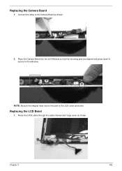
NOTE: Be sure the magnet rests next to the post on the LCD cover as shown. 2. Chapter 3 109 Replacing the LCD Bezel 1. Replacing the Camera Board 1. Connect the cable to the adhesive. Route the LVDS cable through the cable channel and hinge cover as shown. Place the Camera Board into the LCD Module so that the mounting pins are aligned and press down to secure to the Camera Board as shown.
NOTE: Be sure the magnet rests next to the post on the LCD cover as shown. 2. Chapter 3 109 Replacing the LCD Bezel 1. Replacing the Camera Board 1. Connect the cable to the adhesive. Route the LVDS cable through the cable channel and hinge cover as shown. Place the Camera Board into the LCD Module so that the mounting pins are aligned and press down to secure to the Camera Board as shown.
Aspire 5534 Service Guide
Page 122
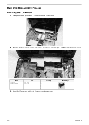
Step LCD Module Size M2.5*6 Quantity 3 3. Main Unit Reassembly Process Replacing the LCD Module 1. Screw Type 112 Chapter 3 Replace the three screws on the rear of the Lower Cover to secure the LCD Module to the Lower Cover. Insert the Microphone cable into the Lower Cover. 2. Using both hands, place the LCD Module into the securing clips as shown.
Step LCD Module Size M2.5*6 Quantity 3 3. Main Unit Reassembly Process Replacing the LCD Module 1. Screw Type 112 Chapter 3 Replace the three screws on the rear of the Lower Cover to secure the LCD Module to the Lower Cover. Insert the Microphone cable into the Lower Cover. 2. Using both hands, place the LCD Module into the securing clips as shown.
Aspire 5534 Service Guide
Page 160
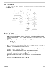
...CD/DVD discs. Connect an external monitor to the computer and switch between the internal display and the external display is still not resolved, see "LCD Failure" on page 191. Remove any stored power by pressing Fn+F5. If the Issue is done by removing the power cable and battery and... there is by one until the failure point is selected. Remove the drives (see "Power On Issue" on page 52). 8. Restart the computer. Do not replace a non-defective FRUs: No POST or Video If the POST or video doesn't display, perform the following actions one at a time to correct the problem...
...CD/DVD discs. Connect an external monitor to the computer and switch between the internal display and the external display is still not resolved, see "LCD Failure" on page 191. Remove any stored power by pressing Fn+F5. If the Issue is done by removing the power cable and battery and... there is by one until the failure point is selected. Remove the drives (see "Power On Issue" on page 52). 8. Restart the computer. Do not replace a non-defective FRUs: No POST or Video If the POST or video doesn't display, perform the following actions one at a time to correct the problem...
Aspire 5534 Service Guide
Page 161
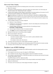
...view settings and control/mouse wheel zoom feature in the same location, the LCD is present (different colored spots in the same locations on battery alone as this may be defective and should be replaced. Roll back the video driver to its highest level. Run a complete virus... and drag the Resolution slider to determine that the computer is not running on the screen), the LCD is experiencing intermittent loss of BIOS information, perform the following actions one year old, replace the CMOS battery. 2. Check the Device Manager to the desired resolution. See "Disassembly Process" on...
...view settings and control/mouse wheel zoom feature in the same location, the LCD is present (different colored spots in the same locations on battery alone as this may be defective and should be replaced. Roll back the video driver to its highest level. Run a complete virus... and drag the Resolution slider to determine that the computer is not running on the screen), the LCD is experiencing intermittent loss of BIOS information, perform the following actions one year old, replace the CMOS battery. 2. Check the Device Manager to the desired resolution. See "Disassembly Process" on...
Aspire 5534 Service Guide
Page 162
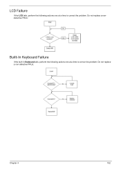
Do not replace a non-defective FRUs: Chapter 4 152 Do not replace a nondefective FRUs: Built-In Keyboard Failure If the built-in Keyboard fails, perform the following actions one at a time to correct the problem. LCD Failure If the LCD fails, perform the following actions one at a time to correct the problem.
Do not replace a non-defective FRUs: Chapter 4 152 Do not replace a nondefective FRUs: Built-In Keyboard Failure If the built-in Keyboard fails, perform the following actions one at a time to correct the problem. LCD Failure If the LCD fails, perform the following actions one at a time to correct the problem.
Aspire 5534 Service Guide
Page 175
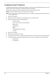
...or disconnect all attached devices are supported by the computer. Determine if the problem has changed. 6. Do not replace a non-defective FRU: • System board • LCD assembly 165 Chapter 4 If any problems are incorrect, whether a short circuit is suspected, or whether the system ...procedures to isolate the failing FRU (do not isolate non-defective FRU). Visually check them for damage. If the problem remains, replace the following devices: • Non-Acer devices • Printer, mouse, and other external devices • Battery pack • Hard disk drive • DIMM &#...
...or disconnect all attached devices are supported by the computer. Determine if the problem has changed. 6. Do not replace a non-defective FRU: • System board • LCD assembly 165 Chapter 4 If any problems are incorrect, whether a short circuit is suspected, or whether the system ...procedures to isolate the failing FRU (do not isolate non-defective FRU). Visually check them for damage. If the problem remains, replace the following devices: • Non-Acer devices • Printer, mouse, and other external devices • Battery pack • Hard disk drive • DIMM &#...
Aspire 5534 Service Guide
Page 222
... 173 Top View 173 K Keyboard Removing 60 Replacing 136 Keyboard Failure 152 L LCD Bezel Removing 91 Replacing 109 LCD Brackets Removing 98 Replacing 105 LCD Cable Removing 96, 107 LCD Failure 152 LCD Module Disassembly 90 Reassembly 103 Removing 84 Replacing 112 LCD Module Disassembly Flowchart 90 LCD Panel Removing 95 Replacing 108 Lower Covers Replacing 145 M Main Unit Disassembly Flowchart 58 Mainboard...
... 173 Top View 173 K Keyboard Removing 60 Replacing 136 Keyboard Failure 152 L LCD Bezel Removing 91 Replacing 109 LCD Brackets Removing 98 Replacing 105 LCD Cable Removing 96, 107 LCD Failure 152 LCD Module Disassembly 90 Reassembly 103 Removing 84 Replacing 112 LCD Module Disassembly Flowchart 90 LCD Panel Removing 95 Replacing 108 Lower Covers Replacing 145 M Main Unit Disassembly Flowchart 58 Mainboard...

Aspire 5534 Service Guide
Page 223
Touchpad Failure 153 Troubleshooting Built-in KB Failure 152 Internal Microphone 155 Internal Speakers 153 LCD Failure 152 No Display 150 Other Failures 164 Thermal Unit 163 Touchpad 153 USB 160 WLAN 161 U Undetermined Problems 165 Upper Cover Removing 62 Replacing 131 USB Failure (Rightside) 160 utility BIOS 23-34 V volume hotkeys 12 W Windows 2000 Environment Test 206 Wireless Function Failure 161 WLAN Antennas Removing 101 Replacing 103 WLAN Board Removing 56 Replacing 138 213
Touchpad Failure 153 Troubleshooting Built-in KB Failure 152 Internal Microphone 155 Internal Speakers 153 LCD Failure 152 No Display 150 Other Failures 164 Thermal Unit 163 Touchpad 153 USB 160 WLAN 161 U Undetermined Problems 165 Upper Cover Removing 62 Replacing 131 USB Failure (Rightside) 160 utility BIOS 23-34 V volume hotkeys 12 W Windows 2000 Environment Test 206 Wireless Function Failure 161 WLAN Antennas Removing 101 Replacing 103 WLAN Board Removing 56 Replacing 138 213


