Aspire 3000 / 3500 / 5000 Service Guide
Page 7
Table of Contents Chapter 1 System Introduction 1 Features 1 System Block Diagram (For Aspire 3000/5000 3 System Block Diagram (For Aspire 3500 4 Board Layout (For Aspire 3000/5000 5 Top View 5 Bottom View 6 Panel 8 Front view 8 Closed front view 9 Left view 9 Right view 10 Rear view ...41 Exit 42 BIOS Flash Utility 43 Chapter 3 Machine Disassembly and Replacement 46 General Information 47 Before You Begin 47 Disassembly Procedure Flowchart 48 Removing the Battery 50 Removing the Hard Disc Drive Module 50 Disassembling the Hard Disc Drive Module 50 Removing the Optical ...
Table of Contents Chapter 1 System Introduction 1 Features 1 System Block Diagram (For Aspire 3000/5000 3 System Block Diagram (For Aspire 3500 4 Board Layout (For Aspire 3000/5000 5 Top View 5 Bottom View 6 Panel 8 Front view 8 Closed front view 9 Left view 9 Right view 10 Rear view ...41 Exit 42 BIOS Flash Utility 43 Chapter 3 Machine Disassembly and Replacement 46 General Information 47 Before You Begin 47 Disassembly Procedure Flowchart 48 Removing the Battery 50 Removing the Hard Disc Drive Module 50 Disassembling the Hard Disc Drive Module 50 Removing the Optical ...
Aspire 3000 / 3500 / 5000 Service Guide
Page 55
... Replacement This chapter contains step-by-step procedures on how to avoid mismatch when putting back the components. To disassemble the computer, you need the following tools: T Wrist grounding strap and conductive mat for preventing electrostatic discharge T Flat-bladed screw driver T ... T Tweezers T Plastic Flat-bladed screw driver T Hexed Screw Driver NOTE: The screws for maintenance and troubleshooting. Chapter 3 46 During the disassembly process, group the screws with the corresponding components to disassemble the notebook computer for the different components vary in size.
... Replacement This chapter contains step-by-step procedures on how to avoid mismatch when putting back the components. To disassemble the computer, you need the following tools: T Wrist grounding strap and conductive mat for preventing electrostatic discharge T Flat-bladed screw driver T ... T Tweezers T Plastic Flat-bladed screw driver T Hexed Screw Driver NOTE: The screws for maintenance and troubleshooting. Chapter 3 46 During the disassembly process, group the screws with the corresponding components to disassemble the notebook computer for the different components vary in size.

Aspire 3000 / 3500 / 5000 Service Guide
Page 56
General Information Before You Begin Before proceeding with the disassembly procedure, make sure that you may need to the system and all power and signal cables from the system . Turn off the power to tear the tape or mylar before you disconnect different FFC/FPC/connectors. 47 Chapter 3 NOTE: Aspire 9100 series product uses mylar or tape to fasten the FFC/FPC/connectors/cable, you do the following: 1. Unplug the AC adapter and all peripherals. 2.
General Information Before You Begin Before proceeding with the disassembly procedure, make sure that you may need to the system and all power and signal cables from the system . Turn off the power to tear the tape or mylar before you disconnect different FFC/FPC/connectors. 47 Chapter 3 NOTE: Aspire 9100 series product uses mylar or tape to fasten the FFC/FPC/connectors/cable, you do the following: 1. Unplug the AC adapter and all peripherals. 2.

Aspire 3000 / 3500 / 5000 Service Guide
Page 57
... components that need to remove the main board, you want to be removed during servicing. For example, if you must first remove the keyboard, then disassemble the inside assembly frame in that order. Start Battery HDD Module *2 HDD HDD Holder *2 Dimm Cover Memory *1 Modem Cover *2 Modem Board Hinge Caps *2 Middle Cover...
... components that need to remove the main board, you want to be removed during servicing. For example, if you must first remove the keyboard, then disassemble the inside assembly frame in that order. Start Battery HDD Module *2 HDD HDD Holder *2 Dimm Cover Memory *1 Modem Cover *2 Modem Board Hinge Caps *2 Middle Cover...

Aspire 3000 / 3500 / 5000 Service Guide
Page 59
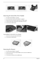
Chapter 3 50 Then remove the HDD cover. 4. Disassembling the Hard Disc Drive Module 1. Take out the HDD from the HDD bracket. Removing the Hard Disc Drive Module 1. See "Removing the Battery" on the other side. 3. Pull the HDD module backwards as shown. 5. Remove two screw securing the HDD bracket. 2. Remove the HDD module. Remove the other two screw on page 50. 2. Remove the screw securing the hard disk drive (HDD) cover. 3. Removing the Battery 1. Unlatch the battery latch then remove the battery.
Chapter 3 50 Then remove the HDD cover. 4. Disassembling the Hard Disc Drive Module 1. Take out the HDD from the HDD bracket. Removing the Hard Disc Drive Module 1. See "Removing the Battery" on the other side. 3. Pull the HDD module backwards as shown. 5. Remove two screw securing the HDD bracket. 2. Remove the HDD module. Remove the other two screw on page 50. 2. Remove the screw securing the hard disk drive (HDD) cover. 3. Removing the Battery 1. Unlatch the battery latch then remove the battery.
Aspire 3000 / 3500 / 5000 Service Guide
Page 60
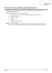
... Drive Module" on page 50. 3. Remove the screw securing the optical disc drove (ODD) module. 4. Push the ODD module outwards with a flat headed screw driver. 5. Disassembling the Optical Disc Drive Module 1. Then remove the ODD bracket. Removing the Memory 1.
... Drive Module" on page 50. 3. Remove the screw securing the optical disc drove (ODD) module. 4. Push the ODD module outwards with a flat headed screw driver. 5. Disassembling the Optical Disc Drive Module 1. Then remove the ODD bracket. Removing the Memory 1.

Aspire 3000 / 3500 / 5000 Service Guide
Page 65
... four screws securing the LCD bezel. 9. See "Removing the Middle Cover" on page 55. 7. Detach the LCD bezel carefully. 10. Disconnect the LCD cable. 16. Disassembling the LCD Module Removing the LCD Bezel 1. See "Removing the LCD Module" on page 53. 3. Disconnect the LCD inverter cable. 13. Remove the four screws...
... four screws securing the LCD bezel. 9. See "Removing the Middle Cover" on page 55. 7. Detach the LCD bezel carefully. 10. Disconnect the LCD cable. 16. Disassembling the LCD Module Removing the LCD Bezel 1. See "Removing the LCD Module" on page 53. 3. Disconnect the LCD inverter cable. 13. Remove the four screws...

Aspire 3000 / 3500 / 5000 Service Guide
Page 67
... 51. 4. See "Removing the Optical Disc Drive Module" on page 51. 5. Tear off the tape holding the power board cable then remove the power board. Disassembling the Main Unit Removing the Upper Case Assembly 1. Remove the three screws securing the upper case assembly. 8. See "Removing the Battery" on page 51. 5. See...
... 51. 4. See "Removing the Optical Disc Drive Module" on page 51. 5. Tear off the tape holding the power board cable then remove the power board. Disassembling the Main Unit Removing the Upper Case Assembly 1. Remove the three screws securing the upper case assembly. 8. See "Removing the Battery" on page 51. 5. See...

Aspire 3000 / 3500 / 5000 Service Guide
Page 121
... CardBus 26 Chipsets 20 contrast hotkeys 16 Controllers 20 Core logic 20 CPU core voltage 20 I/O voltage 20 package 20 type 20 D DIMM Combinations 21 Disassembly Index Index Battery Pack 49 Procedure Flowchart 48 Display 2 display hotkeys 16 Display Standby Mode 29 DVD-ROM Interface 23, 24 E Environmental Requirements 29 Error...
... CardBus 26 Chipsets 20 contrast hotkeys 16 Controllers 20 Core logic 20 CPU core voltage 20 I/O voltage 20 package 20 type 20 D DIMM Combinations 21 Disassembly Index Index Battery Pack 49 Procedure Flowchart 48 Display 2 display hotkeys 16 Display Standby Mode 29 DVD-ROM Interface 23, 24 E Environmental Requirements 29 Error...

Aspire 3000 / 5000 User's Guide
Page 77
Batteries may occasionally misfire or appear as black or red Do not disassemble or dispose of used with high-precision manufacturing techniques. AVOID EXPOSURE TO BEAM. EVITE EXPONERSE A LOS RAYOS. LAVATTAESSA OLET ALTTINA LASERSÅTEILYLLE. Keep them ... LCD pixel statement The LCD unit is properly grounded. 15 Use only the proper type of electric shock from the wall outlet before serving or disassembling this computer is located on the drive. Nevertheless, some pixels may explode if not handled properly. Laser compliance statement The CD or DVD drive used...
Batteries may occasionally misfire or appear as black or red Do not disassemble or dispose of used with high-precision manufacturing techniques. AVOID EXPOSURE TO BEAM. EVITE EXPONERSE A LOS RAYOS. LAVATTAESSA OLET ALTTINA LASERSÅTEILYLLE. Keep them ... LCD pixel statement The LCD unit is properly grounded. 15 Use only the proper type of electric shock from the wall outlet before serving or disassembling this computer is located on the drive. Nevertheless, some pixels may explode if not handled properly. Laser compliance statement The CD or DVD drive used...

Aspire 3000 / 5000 User's Guide
Page 78
... for products with wireless LAN and/or Bluetooth only. Patent Nos. 4,631,603; 4,819,098; 4,907,093; 5,315,448; and 6,516,132. Reverse engineering or disassembly is for home and other intellectual property rights. Depending on the recorded image and does not constitute a malfunction. Below information is for wireless use. This...
... for products with wireless LAN and/or Bluetooth only. Patent Nos. 4,631,603; 4,819,098; 4,907,093; 5,315,448; and 6,516,132. Reverse engineering or disassembly is for home and other intellectual property rights. Depending on the recorded image and does not constitute a malfunction. Below information is for wireless use. This...


