
Service Guide
Page 12
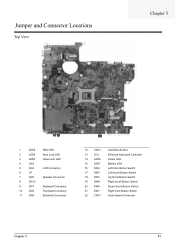
Board Layout Top View 1 23 4 5 6 12 14 15 7 8 9 10 11 13 18 16 17 19 21 22 20 1 LED3 2 LED4 3 LED5 4 CN3 5 CN4 6 U7 7 CN5 8 CN10 9 ... U12 14 LED6 15 LED7 16 SW4 17 SW5 18 SW3 19 SW6 20 SW8 21 SW7 22 CN17 Card Bus Socket Winbond Keyboard Controller Power LED Battery LED Left Click Button Switch Left Scroll Button Switch Up Scroll Button Switch Right Scroll Button Switch Down Scroll Button Switch Right Click...
Board Layout Top View 1 23 4 5 6 12 14 15 7 8 9 10 11 13 18 16 17 19 21 22 20 1 LED3 2 LED4 3 LED5 4 CN3 5 CN4 6 U7 7 CN5 8 CN10 9 ... U12 14 LED6 15 LED7 16 SW4 17 SW5 18 SW3 19 SW6 20 SW8 21 SW7 22 CN17 Card Bus Socket Winbond Keyboard Controller Power LED Battery LED Left Click Button Switch Left Scroll Button Switch Up Scroll Button Switch Right Scroll Button Switch Down Scroll Button Switch Right Click...

Service Guide
Page 67
Removing the Keyboard and LCD Module 1. Lift the keyboard up and remove the power board cover as shown. 3. Disconnect the keyboard cable from the main board and remove the keyboard from the underside of the power board cable. 6. Chapter 3 61 Disconnect both ends of the main unit. 7. Remove the six screws securing the hinges. Turn the...
Removing the Keyboard and LCD Module 1. Lift the keyboard up and remove the power board cover as shown. 3. Disconnect the keyboard cable from the main board and remove the keyboard from the underside of the power board cable. 6. Chapter 3 61 Disconnect both ends of the main unit. 7. Remove the six screws securing the hinges. Turn the...

Service Guide
Page 69
... and remove the three screws fastening the power board. 3. Remove the main board. Remove the eight screws fastening the upper case assembly to the upper case assembly. 2. Disconnect both ends of the audio board cable as shown. 3. Remove the power board from the lower case assembly Disassembling the Lower... Case Assembly Removing the Main Board 1. Gently lift off the upper case assembly from the main unit. 4. ...
... and remove the three screws fastening the power board. 3. Remove the main board. Remove the eight screws fastening the upper case assembly to the upper case assembly. 2. Disconnect both ends of the audio board cable as shown. 3. Remove the power board from the lower case assembly Disassembling the Lower... Case Assembly Removing the Main Board 1. Gently lift off the upper case assembly from the main unit. 4. ...
Service Guide
Page 77
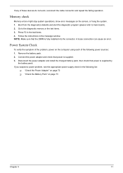
...board). 2. Follow the instructions in the test items. 4. Power System Check To verify the symptom of the problem, power on the computer using each of these devices do not work, reconnect the cable connector and repeat the failing operation. A loose connection can cause an error. Connect the power adapter and check that power... (please refer to the diagnostic memory in the following power sources: 1. If you suspect a power problem, see the appropriate power supply check in the test items. 3. NOTE: Make sure that power is supplied by the battery pack. Remove the battery pack...
...board). 2. Follow the instructions in the test items. 4. Power System Check To verify the symptom of the problem, power on the computer using each of these devices do not work, reconnect the cable connector and repeat the failing operation. A loose connection can cause an error. Connect the power adapter and check that power... (please refer to the diagnostic memory in the following power sources: 1. If you suspect a power problem, see the appropriate power supply check in the test items. 3. NOTE: Make sure that power is supplied by the battery pack. Remove the battery pack...
Service Guide
Page 78
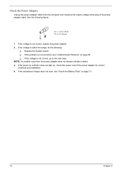
... voltage is not corrected, see "Check the Battery Pack" on indicator does not light up, check the power cord of the power adapter cable. See the following : T Replace the System board. NOTE: An audible noise from the computer and measure the output voltage at the plug of the... power adapter for correct continuity and installation. 4. Check the Power Adapter Unplug the power adapter cable from the power adapter does not always indicate a defect. ...
... voltage is not corrected, see "Check the Battery Pack" on indicator does not light up, check the power cord of the power adapter cable. See the following : T Replace the System board. NOTE: An audible noise from the computer and measure the output voltage at the plug of the... power adapter for correct continuity and installation. 4. Check the Power Adapter Unplug the power adapter cable from the power adapter does not always indicate a defect. ...
Service Guide
Page 79
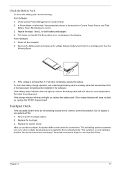
...the touchpad doesn't work, do the following: From Software: 1. Replace the system board. Check the Battery Pack To check the battery pack, do the following actions one at a time to room temperature. In Power Meter, confirm that has less than 7.5 Vdc after recharging, replace the battery. ...the steps 1 and 2, for a short time. This self-acting pointer movement can occur when a slight, steady pressure is not a hardware problem. Power off the computer. 2. Re-install the battery pack. If the voltage is on the screen for both battery and adapter. 4. If the charge indicator ...
...the touchpad doesn't work, do the following: From Software: 1. Replace the system board. Check the Battery Pack To check the battery pack, do the following actions one at a time to room temperature. In Power Meter, confirm that has less than 7.5 Vdc after recharging, replace the battery. ...the steps 1 and 2, for a short time. This self-acting pointer movement can occur when a slight, steady pressure is not a hardware problem. Power off the computer. 2. Re-install the battery pack. If the voltage is on the screen for both battery and adapter. 4. If the charge indicator ...
Service Guide
Page 83
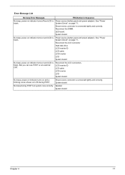
...and correctly. But you can see POST on page 71.. No beep, power-on indicator turns on and LCD is blank. See "Power System Check" on indicator turns off and LCD is blank. LED board. Reconnect the LCD connector Hard disk drive LCD inverter ID LCD cable ...LCD Inverter LCD System board No beep, power-on indicator turns on and LCD is blank. Speaker System board Chapter 4 77 System board. Power source (battery pack and power adapter). Power source (battery pack and power adapter). Reconnect the LCD connectors. Error Message List No beep...
...and correctly. But you can see POST on page 71.. No beep, power-on indicator turns on and LCD is blank. See "Power System Check" on indicator turns off and LCD is blank. LED board. Reconnect the LCD connector Hard disk drive LCD inverter ID LCD cable ...LCD Inverter LCD System board No beep, power-on indicator turns on and LCD is blank. Speaker System board Chapter 4 77 System board. Power source (battery pack and power adapter). Power source (battery pack and power adapter). Reconnect the LCD connectors. Error Message List No beep...

Service Guide
Page 86
Check for SMART drive (optional) Shadow option ROMs Set up Power Management Initialize security engine (optional) Enable hardware interrupts Determine number of ATA and SCSI drives Set time of ATA drives (optional) Initialize hard-disk controllers ... PnP Option ROMs Clear parity checkers Display MultiBoot menu Clear screen (optional) Check virus and backup reminders Try to UserPatch2 Build MPTABLE for multi-processor boards Install CD ROM for boot Clear huge ES segment register Fixup Multi Processor table Search for errors POST done- 8Ch 8Fh 90h 91h 92h 93h...
Check for SMART drive (optional) Shadow option ROMs Set up Power Management Initialize security engine (optional) Enable hardware interrupts Determine number of ATA and SCSI drives Set time of ATA drives (optional) Initialize hard-disk controllers ... PnP Option ROMs Clear parity checkers Display MultiBoot menu Clear screen (optional) Check virus and backup reminders Try to UserPatch2 Build MPTABLE for multi-processor boards Install CD ROM for boot Clear huge ES segment register Fixup Multi Processor table Search for errors POST done- 8Ch 8Fh 90h 91h 92h 93h...

Service Guide
Page 88
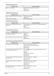
... system runs correctly Reconnect the inverter board Inverter board System board Power-Related Symptoms Symptom / Error Power shuts down during operation The system doesn't power-on page 71. Battery pack Power adapter Hard drive & battery connection board System board Power source (battery pack and power adapter). Hold and press the power switch for more than 4 seconds. System board 82 Chapter 4 Action in Sequence...
... system runs correctly Reconnect the inverter board Inverter board System board Power-Related Symptoms Symptom / Error Power shuts down during operation The system doesn't power-on page 71. Battery pack Power adapter Hard drive & battery connection board System board Power source (battery pack and power adapter). Hold and press the power switch for more than 4 seconds. System board 82 Chapter 4 Action in Sequence...
Service Guide
Page 89
...damaged. LCD cover switch System board Chapter 4 83 LCD cover switch System board See "Save to Disk (S4)" on page 45. Hard disk connection board Hard disk drive System board See "Save to execute "Load Default Settings, then reboot system. Power-Related Symptoms Symptom / Error ...Battery can't be charged Action in Sequence Power Management-Related Symptoms Symptom / Error The system will...
...damaged. LCD cover switch System board Chapter 4 83 LCD cover switch System board See "Save to Disk (S4)" on page 45. Hard disk connection board Hard disk drive System board See "Save to execute "Load Default Settings, then reboot system. Power-Related Symptoms Symptom / Error ...Battery can't be charged Action in Sequence Power Management-Related Symptoms Symptom / Error The system will...
Service Guide
Page 90
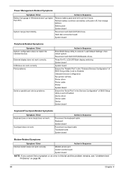
...Refresh battery (continue use battery until power off, then charge battery). Onboard Devices Configuration Run printer self-test. Action in this list and the problem remains, see "Undetermined Problems" on page 86. 84 Chapter 4 Touchpad board System board Modem-Related Symptoms Symptom / Error ...Reconnect hard disk/CD-ROM/diskette drives. Device driver Device cable Device System board Keyboard/Touchpad-Related Symptoms Symptom / Error Keyboard (one or more keys) does not work . Power Management-Related Symptoms Symptom / Error Action in Sequence Battery fuel gauge in ...
...Refresh battery (continue use battery until power off, then charge battery). Onboard Devices Configuration Run printer self-test. Action in this list and the problem remains, see "Undetermined Problems" on page 86. 84 Chapter 4 Touchpad board System board Modem-Related Symptoms Symptom / Error ...Reconnect hard disk/CD-ROM/diskette drives. Device driver Device cable Device System board Keyboard/Touchpad-Related Symptoms Symptom / Error Keyboard (one or more keys) does not work . Power Management-Related Symptoms Symptom / Error Action in Sequence Battery fuel gauge in ...

Service Guide
Page 92
... are supported by the computer. Power-on page 71.): 1. Undetermined Problems The diagnostic problems does not identify which adapter or device failed, which installed devices are found, replace the FRU. 3. Do not replace a non-defective FRU: T System board T LCD assembly 86 Chapter 4... Follow these procedures to isolate the failing FRU (do not isolate non-defective FRU). Visually check them for damage. If the problem remains, replace the following devices: T Non-Acer devices T Printer, mouse, and other ...
... are supported by the computer. Power-on page 71.): 1. Undetermined Problems The diagnostic problems does not identify which adapter or device failed, which installed devices are found, replace the FRU. 3. Do not replace a non-defective FRU: T System board T LCD assembly 86 Chapter 4... Follow these procedures to isolate the failing FRU (do not isolate non-defective FRU). Visually check them for damage. If the problem remains, replace the following devices: T Non-Acer devices T Printer, mouse, and other ...
Service Guide
Page 93
... U12 14 LED6 15 LED7 16 SW4 17 SW5 18 SW3 19 SW6 20 SW8 21 SW7 22 CN17 Card Bus Socket Winbond Keyboard Controller Power LED Battery LED Left Click Button Switch Left Scroll Button Switch Up Scroll Button Switch Right Scroll Button Switch Down Scroll Button Switch Right Click...
... U12 14 LED6 15 LED7 16 SW4 17 SW5 18 SW3 19 SW6 20 SW8 21 SW7 22 CN17 Card Bus Socket Winbond Keyboard Controller Power LED Battery LED Left Click Button Switch Left Scroll Button Switch Up Scroll Button Switch Right Scroll Button Switch Down Scroll Button Switch Right Click...
Service Guide
Page 97
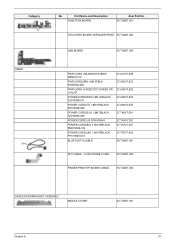
... 6 91 Part Name and Description FUNCTION BOARD Acer Part No. 55.TG607.001 TOUCHPAD BOARD W/FINGER PRINT 55.TG607.002 USB BOARD 55.TG607.003 PWR CORD V943B30001218008 DANISH 3P PWR CORD(ISR)1.8M 3PBLK FZ0I0008-038 PWR CORD V50CB3T3012180QD TW110V,3P POWER CORD(SWI)1.8M 3PBLACK FZ010008-011 POWER CORD(IT) 1.8M 3PBLACK FZ010008-008...
... 6 91 Part Name and Description FUNCTION BOARD Acer Part No. 55.TG607.001 TOUCHPAD BOARD W/FINGER PRINT 55.TG607.002 USB BOARD 55.TG607.003 PWR CORD V943B30001218008 DANISH 3P PWR CORD(ISR)1.8M 3PBLK FZ0I0008-038 PWR CORD V50CB3T3012180QD TW110V,3P POWER CORD(SWI)1.8M 3PBLACK FZ010008-011 POWER CORD(IT) 1.8M 3PBLACK FZ010008-008...


