
Aspire 4220 / 4520 User's Guide EN
Page 6
... not limited to external RF transmissions.. For safety reasons, do so. Keep them may be using your device in health care facilities when any regulations posted in use is completed. Do not place credit cards or other magnetic storage media near the device, because information stored on them out of the...
... not limited to external RF transmissions.. For safety reasons, do so. Keep them may be using your device in health care facilities when any regulations posted in use is completed. Do not place credit cards or other magnetic storage media near the device, because information stored on them out of the...
Aspire 4220 / 4520 User's Guide EN
Page 61
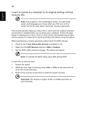
.... Before performing a restore operation, please check the BIOS settings. 1 Check to see if Acer disk-to perform system recovery. Note: To activate the BIOS utility, press during POST. To start the recovery process: 1 Restart the system. 2 While the Acer logo is showing, press + at the same time to enter the recovery process. 3 Refer...
.... Before performing a restore operation, please check the BIOS settings. 1 Check to see if Acer disk-to perform system recovery. Note: To activate the BIOS utility, press during POST. To start the recovery process: 1 Restart the system. 2 While the Acer logo is showing, press + at the same time to enter the recovery process. 3 Refer...

Aspire 4220 / 4520 User's Guide EN
Page 94
..., activate the BIOS utility, then select Security from the categories listed at the bottom of the screen. To activate the BIOS utility, press during the POST; English 75 BIOS utility The BIOS utility is being displayed. while the notebook PC logo is a hardware configuration program built into your computer's BIOS. Password...
..., activate the BIOS utility, then select Security from the categories listed at the bottom of the screen. To activate the BIOS utility, press during the POST; English 75 BIOS utility The BIOS utility is being displayed. while the notebook PC logo is a hardware configuration program built into your computer's BIOS. Password...

Aspire 4220 / 4520 User's Guide EN
Page 99
...or an authorized service center. Error messages Corrective action CMOS battery bad Contact your dealer or an authorized service center. Equipment configuration error Press (during POST) to enter the BIOS utility, then press Exit in the BIOS utility to reboot. Solutions to reboot. The following table lists the error messages ... "Error messages" below. 80 English Troubleshooting This chapter shows you how to deal with the recommended course of action. Memory size mismatch Press (during POST) to open the computer yourself; See "Requesting service" on page 43.
...or an authorized service center. Error messages Corrective action CMOS battery bad Contact your dealer or an authorized service center. Equipment configuration error Press (during POST) to enter the BIOS utility, then press Exit in the BIOS utility to reboot. Solutions to reboot. The following table lists the error messages ... "Error messages" below. 80 English Troubleshooting This chapter shows you how to deal with the recommended course of action. Memory size mismatch Press (during POST) to open the computer yourself; See "Requesting service" on page 43.

Service Guide
Page 45
...: nVidia 5.67.32.02.06 KBC Version : V0.013 Serial Number : xxxxxxxxxxxxxxxxxxxxxx Asset Tag Number : Product Name : Manufacturer Name : Acer UUID: xxxxxxxxxxxxxxxxxxxxxxxxxxxxxxxx F1 Help Esc Exit Chapter 2 Select Item Select Menu F5/F6 Change Values Enter Select Sub-Menu F9 Setup Defaults F10 Save...BIOS SETUP Utility. Press m to Chapter 4 Troubleshooting when problem arises. In this utility. To activate the BIOS Utility, press m during POST to "disabled". If you may need to "enabled". Chapter 2 System Utilities BIOS Setup Utility The BIOS Setup Utility is set the ...
...: nVidia 5.67.32.02.06 KBC Version : V0.013 Serial Number : xxxxxxxxxxxxxxxxxxxxxx Asset Tag Number : Product Name : Manufacturer Name : Acer UUID: xxxxxxxxxxxxxxxxxxxxxxxxxxxxxxxx F1 Help Esc Exit Chapter 2 Select Item Select Menu F5/F6 Change Values Enter Select Sub-Menu F9 Setup Defaults F10 Save...BIOS SETUP Utility. Press m to Chapter 4 Troubleshooting when problem arises. In this utility. To activate the BIOS Utility, press m during POST to "disabled". If you may need to "enabled". Chapter 2 System Utilities BIOS Setup Utility The BIOS Setup Utility is set the ...
Service Guide
Page 49
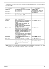
... parameters in the system. Determines if Customer Logo will be in CRT (or projector) only mode. Option: Enabled or Disabled Enables, disables Boot Menu during POST. Format: HH:MM:SS (hour:minute:second) System Time Sets the system date. Disabled: Customer Logo is not displayed, and Summary Screen is set to...
... parameters in the system. Determines if Customer Logo will be in CRT (or projector) only mode. Option: Enabled or Disabled Enables, disables Boot Menu during POST. Format: HH:MM:SS (hour:minute:second) System Time Sets the system date. Disabled: Customer Logo is not displayed, and Summary Screen is set to...

Service Guide
Page 75
... to "Power-On Self-Test (POST) Error Message" on page 74 "Intermittent Problems" on page 85 "Undetermined Problems" on page 86 Chapter 4 69 Use the following procedure as possible. 2. No beep or error codes are intended to test only Acer products. Symptoms cannot be re-created... (intermittent problems). POST does not complete. Other symptoms (i.e. Obtain the failing symptoms in as much detail as a guide for computer problems....
... to "Power-On Self-Test (POST) Error Message" on page 74 "Intermittent Problems" on page 85 "Undetermined Problems" on page 86 Chapter 4 69 Use the following procedure as possible. 2. No beep or error codes are intended to test only Acer products. Symptoms cannot be re-created... (intermittent problems). POST does not complete. Other symptoms (i.e. Obtain the failing symptoms in as much detail as a guide for computer problems....
Service Guide
Page 80
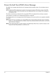
... installed. Do not replace a non-defective FRU. Some of them display information about a hardware device, e.g., the amount of the error messages occur during POST. This index can also help you make changes in the computer. The most likely cause is not listed, see "Undetermined Problems" on the screen and... function. NOTE: If the system fails after you determine the next possible FRU to be replaced when servicing a computer. Power-On Self-Test (POST) Error Message The POST error message index lists the error message and their possible causes. If the symptom is listed first.
... installed. Do not replace a non-defective FRU. Some of them display information about a hardware device, e.g., the amount of the error messages occur during POST. This index can also help you make changes in the computer. The most likely cause is not listed, see "Undetermined Problems" on the screen and... function. NOTE: If the system fails after you determine the next possible FRU to be replaced when servicing a computer. Power-On Self-Test (POST) Error Message The POST error message index lists the error message and their possible causes. If the symptom is listed first.

Service Guide
Page 82
... Failed Device Address Conflict Allocation Error for device Failing Bits: nnnn Fixed Disk n Invalid System Configuration Data I/O device IRQ conflict Operating system not found by POST differed from CMOS Diskette drive A error Incorrect Drive A type - DIMM System board Check the drive is defined with the proper diskette type in BIOS Setup...
... Failed Device Address Conflict Allocation Error for device Failing Bits: nnnn Fixed Disk n Invalid System Configuration Data I/O device IRQ conflict Operating system not found by POST differed from CMOS Diskette drive A error Incorrect Drive A type - DIMM System board Check the drive is defined with the proper diskette type in BIOS Setup...
Service Guide
Page 83
...indicator turns on and a blinking cursor shown on an external CRT. Power source (battery pack and power adapter). But you can see POST on LCD during POST but system runs correctly. Speaker System board Chapter 4 77 Ensure every connector is connected tightly and correctly. System board No beep during... POST. No beep, power-on indicator turns on indicator turns off and LCD is blank. Error Message List No beep Error Messages ...
...indicator turns on and a blinking cursor shown on an external CRT. Power source (battery pack and power adapter). But you can see POST on LCD during POST but system runs correctly. Speaker System board Chapter 4 77 Ensure every connector is connected tightly and correctly. System board No beep during... POST. No beep, power-on indicator turns on indicator turns off and LCD is blank. Error Message List No beep Error Messages ...

Service Guide
Page 84
... 1Ch 20h 22h 24h 26h 28h 29h 2Ah 2Ch 2Eh 2Fh 30h 32h 33h 36h 38h 3Ah 3Ch 3Dh 42h 45h Beeps 1-2-2-3 1-3-1-1 1-3-1-3 1-3-4-1 1-3-4-3 1-4-1-1 78 POST Routine Description Verify Real Mode Disable Non-Maskable Interrupt (NMI) Get CPU type Initialize system hardware Initialize chipset with initial...initialization Reset Programmable Interrupt Controller Test DRAM refresh Test 8742 Keyboard Controller Set ES segment register to 4 GB Enable A20 line Autosize DRAM Initialize POST Memory Manager Clear 215 KB base RAM RAM failure on address line xxxx RAM failure on data bits xxxx of low byte of memory ...
... 1Ch 20h 22h 24h 26h 28h 29h 2Ah 2Ch 2Eh 2Fh 30h 32h 33h 36h 38h 3Ah 3Ch 3Dh 42h 45h Beeps 1-2-2-3 1-3-1-1 1-3-1-3 1-3-4-1 1-3-4-3 1-4-1-1 78 POST Routine Description Verify Real Mode Disable Non-Maskable Interrupt (NMI) Get CPU type Initialize system hardware Initialize chipset with initial...initialization Reset Programmable Interrupt Controller Test DRAM refresh Test 8742 Keyboard Controller Set ES segment register to 4 GB Enable A20 line Autosize DRAM Initialize POST Memory Manager Clear 215 KB base RAM RAM failure on address line xxxx RAM failure on data bits xxxx of low byte of memory ...

Service Guide
Page 85
... copyright notice Display CPU type and speed Initialize EISA board Test keyboard Set key click if enabled Test for unexpected interrupts Initialize POST display service Display prompt "Press F2 to enter SETUP" Disable CPU cache Test RAM between 512 and 640 KB Test extended ... errors Check for keyboard errors Set up hardware interrupt vectors Initialize coprocessor if present Disable onboard Super I/O ports and IRQs Late POST device initialization Detect and install external RS232 ports Configure non-MCD IDE controllers Detect and install external parallel ports Initialize PC-compatible ...
... copyright notice Display CPU type and speed Initialize EISA board Test keyboard Set key click if enabled Test for unexpected interrupts Initialize POST display service Display prompt "Press F2 to enter SETUP" Disable CPU cache Test RAM between 512 and 640 KB Test extended ... errors Check for keyboard errors Set up hardware interrupt vectors Initialize coprocessor if present Disable onboard Super I/O ports and IRQs Late POST device initialization Detect and install external RS232 ports Configure non-MCD IDE controllers Detect and install external parallel ports Initialize PC-compatible ...

Service Guide
Page 86
...MPTABLE for multi-processor boards Install CD ROM for boot Clear huge ES segment register Fixup Multi Processor table Search for errors POST done- Check for SMART drive (optional) Shadow option ROMs Set up Power Management Initialize security engine (optional) Enable hardware ...time of ATA drives (optional) Initialize hard-disk controllers Initialize local-bus hard-disk controllers Jump to boot with INT 19 Initialize POST Error Manager (PEM) Initialize error logging Initialize error display function Initialize system error handler PnPnd dual CMOS (optional) Initialize notebook docking...
...MPTABLE for multi-processor boards Install CD ROM for boot Clear huge ES segment register Fixup Multi Processor table Search for errors POST done- Check for SMART drive (optional) Shadow option ROMs Set up Power Management Initialize security engine (optional) Enable hardware ...time of ATA drives (optional) Initialize hard-disk controllers Initialize local-bus hard-disk controllers Jump to boot with INT 19 Initialize POST Error Manager (PEM) Initialize error logging Initialize error display function Initialize system error handler PnPnd dual CMOS (optional) Initialize notebook docking...
Service Guide
Page 87
... E1h E2h E3h E4h E5h E6h E7h E8h E9h EAh EBh ECh EDh EEh EFh F0h F1h F2h F3h F4h F5h F6h F7h Beeps Beeps 1 POST Routine Description Unknown interrupt Initialize the chipset Initialize the bridge Initialize the CPU Initialize the system timer Initialize system I/O Check force recovery boot Checksum BIOS...
... E1h E2h E3h E4h E5h E6h E7h E8h E9h EAh EBh ECh EDh EEh EFh F0h F1h F2h F3h F4h F5h F6h F7h Beeps Beeps 1 POST Routine Description Unknown interrupt Initialize the chipset Initialize the bridge Initialize the CPU Initialize the system timer Initialize system I/O Check force recovery boot Checksum BIOS...


