
Aspire 4220 / 4520 User's Guide EN
Page 6
... telephone lines from lightning, do not use is completed. Additional safety information Your device and its normal operating positions. For safety reasons, turn off your laptop under the following conditions. Parts of electric shock from the equipment when not in any radio transmitting equipment, including wireless phones, may contain small parts...
... telephone lines from lightning, do not use is completed. Additional safety information Your device and its normal operating positions. For safety reasons, turn off your laptop under the following conditions. Parts of electric shock from the equipment when not in any radio transmitting equipment, including wireless phones, may contain small parts...
Service Guide
Page 37
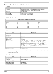
... Bus Power Management Interface Specification, USB1.1/2.0, IEEE 1394 1.0, USB/1394 CD-ROM Boot Up support, PC Card 95 (PCMCIA 3.0 Compliant Device), Acer WMI, Acer LED, Acer VRAM, Acer MDA 2007 requirements, WfM 2.0, PXE (Preboot Execution Environment), BIS 1.0 (Boot Integrity Service Application Program Interface), Set by setup manual NOTE: If...scheme control 256MB / 512MB / 1GB Always enabled Always enabled Fixed in write-back Specification Chapter 1 31 G and F; Last, reboot the laptop. Then you need to check PXE version, press F2 to enter BIOS then enable boot from LAN function.
... Bus Power Management Interface Specification, USB1.1/2.0, IEEE 1394 1.0, USB/1394 CD-ROM Boot Up support, PC Card 95 (PCMCIA 3.0 Compliant Device), Acer WMI, Acer LED, Acer VRAM, Acer MDA 2007 requirements, WfM 2.0, PXE (Preboot Execution Environment), BIS 1.0 (Boot Integrity Service Application Program Interface), Set by setup manual NOTE: If...scheme control 256MB / 512MB / 1GB Always enabled Always enabled Fixed in write-back Specification Chapter 1 31 G and F; Last, reboot the laptop. Then you need to check PXE version, press F2 to enter BIOS then enable boot from LAN function.

Service Guide
Page 64
Pull out the HDD module by the two bracket as shown. 2. Remove the screw fastening the ODD module. 7. To access the internal laptop components, you have to gently push out the ODD module as shown. Removing the ODD Module 6. Press and release the PC dummy card from the ...PC slot as shown. Turn over the laptop and remove the nine screws fastening the back panel. 3. Remove the two screws fastening the HDD module bracket. 5. Use a flat screwdriver to first remove the...
Pull out the HDD module by the two bracket as shown. 2. Remove the screw fastening the ODD module. 7. To access the internal laptop components, you have to gently push out the ODD module as shown. Removing the ODD Module 6. Press and release the PC dummy card from the ...PC slot as shown. Turn over the laptop and remove the nine screws fastening the back panel. 3. Remove the two screws fastening the HDD module bracket. 5. Use a flat screwdriver to first remove the...


