
TravelMate 2420 / Aspire 3620 Service Guide
Page 19
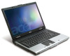
Note: Do not cover or obstruct the opening of the fan. Chapter 1 11 4 Rear Panel Ethernet (RJ-45) Connects to an Ethernet 10/100/1000based network. # 1 Icon Item DC-in position. Powers the computer # Item 1 Battery lock 2 Cooling fan Description Locks the battery in jack External display (VGA) port Battery Bottom Panel Description Connects to a display device(e.g., external monitor, LCD projector). Helps keep the computer cool. Connects to an AC adapter.
Note: Do not cover or obstruct the opening of the fan. Chapter 1 11 4 Rear Panel Ethernet (RJ-45) Connects to an Ethernet 10/100/1000based network. # 1 Icon Item DC-in position. Powers the computer # Item 1 Battery lock 2 Cooling fan Description Locks the battery in jack External display (VGA) port Battery Bottom Panel Description Connects to a display device(e.g., external monitor, LCD projector). Helps keep the computer cool. Connects to an AC adapter.
TravelMate 2420 / Aspire 3620 Service Guide
Page 59
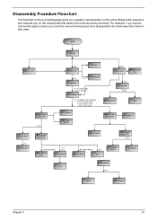
Start Battery Middle Cover H*2 DIMM Cover Memory P*1 Keyboard ODD Module E*1 J*2 on bottom side K*2 on top side LCD Module E*1 on upper case assemby E*12 on bottom side F*3 on bottom side A*2 on the components that order. For example, if you want to be ... you must first remove the keyboard, then disassemble the inside assembly frame in that need to remove the system board, you on rear side H*3 HDD Cover Wireless LAN Card O*4 HDD Module M*4 HDD Bracket HDD Lower Case Assembly O*2 RTC Battery Bluetooth Module Upper Case Assembly Microphone Lower Case *2 Speaker Set ...
Start Battery Middle Cover H*2 DIMM Cover Memory P*1 Keyboard ODD Module E*1 J*2 on bottom side K*2 on top side LCD Module E*1 on upper case assemby E*12 on bottom side F*3 on bottom side A*2 on the components that order. For example, if you want to be ... you must first remove the keyboard, then disassemble the inside assembly frame in that need to remove the system board, you on rear side H*3 HDD Cover Wireless LAN Card O*4 HDD Module M*4 HDD Bracket HDD Lower Case Assembly O*2 RTC Battery Bluetooth Module Upper Case Assembly Microphone Lower Case *2 Speaker Set ...

TravelMate 2420 / Aspire 3620 Service Guide
Page 62
... the Wireless LAN Card/the HDD Module/the Memory/the ODD Module and the LCD Module Removing the Memory and the HDD Module 1. Pop out the memory carefully. 4. Detach the HDD cover from the wireless LAN card. 5. Disconnect wireless main and auxiliary antenna from the main unit.... 8. Remove the five screws fastening the DIMM cover. 2. Detach the DIMM cover carefully. 3. Remove the four screws fastening the HDD module. 9....
... the Wireless LAN Card/the HDD Module/the Memory/the ODD Module and the LCD Module Removing the Memory and the HDD Module 1. Pop out the memory carefully. 4. Detach the HDD cover from the wireless LAN card. 5. Disconnect wireless main and auxiliary antenna from the main unit.... 8. Remove the five screws fastening the DIMM cover. 2. Detach the DIMM cover carefully. 3. Remove the four screws fastening the HDD module. 9....

TravelMate 2420 / Aspire 3620 Service Guide
Page 63
Detach the middle cover from the launch board. Disconnect the microphone cable from the main uiit carefully. 2. Chapter 3 55 Remove the middle cover (with launch board and microphone) from the launch board. 3. Push the ODD module outwards then remove it. Removing the ODD Module 1. Removing the LCD Module 1. First, remove the screw fastening the ODD module as shown. 2. Disconnect the launch board FFC from the main unit. 4.
Detach the middle cover from the launch board. Disconnect the microphone cable from the main uiit carefully. 2. Chapter 3 55 Remove the middle cover (with launch board and microphone) from the launch board. 3. Push the ODD module outwards then remove it. Removing the ODD Module 1. Removing the LCD Module 1. First, remove the screw fastening the ODD module as shown. 2. Disconnect the launch board FFC from the main unit. 4.

TravelMate 2420 / Aspire 3620 Service Guide
Page 64
Remove the keyboard from the middle cover. 6. Take out the microphone from the main unit. 12. Disconnect the LCD cable. 15. Remove the two screws fastening the launch board. 7. Then remove the launch board from the main unit. 14. Turn over the notebook then remove two screws fastening the LCD module. 56 Chapter 3 Remove the screw holding the keyboard. 9. Tear off the tapes fastening the wireless antenna cable. 13. Pull the antenna set from the middle cover. . 8. Turn over the keyboard as shown. 10. Disconnect the keyboard cable. 11. 5.
Remove the keyboard from the middle cover. 6. Take out the microphone from the main unit. 12. Disconnect the LCD cable. 15. Remove the two screws fastening the launch board. 7. Then remove the launch board from the main unit. 14. Turn over the notebook then remove two screws fastening the LCD module. 56 Chapter 3 Remove the screw holding the keyboard. 9. Tear off the tapes fastening the wireless antenna cable. 13. Pull the antenna set from the middle cover. . 8. Turn over the keyboard as shown. 10. Disconnect the keyboard cable. 11. 5.

TravelMate 2420 / Aspire 3620 Service Guide
Page 70
... the LCD inverter from the LCD cover, then disconnect the LCD cable from the LCD panel on the other side. 11. Detach the wireless antenna set from the inverter. 6. Remove the four screws holding the LCD to the LCD panel. 7. Then remove the LCD hinges from the LCD module. 4. Disassembling the LCD Module 1. Remove the two screws holding the LCD bezel...
... the LCD inverter from the LCD cover, then disconnect the LCD cable from the LCD panel on the other side. 11. Detach the wireless antenna set from the inverter. 6. Remove the four screws holding the LCD to the LCD panel. 7. Then remove the LCD hinges from the LCD module. 4. Disassembling the LCD Module 1. Remove the two screws holding the LCD bezel...
TravelMate 2420 / Aspire 3620 Service Guide
Page 87
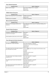
... system doesn't enter standby mode after closing the LCD The system doesn't resume from standby mode after opening the LCD. Action in Sequence See "Save to Disk (S4)" on page 36. Keyboard (if control is damaged. LCD cover switch System board Chapter 4 79 Internal speakers make...count (size) appears different from the keyboard) Hard disk drive System board Press Fn+oand see if the computer enters hibernation mode. LCD cover switch System board See "Save to execute "Load Default Settings, then reboot system. Action in Sequence Power Management-Related Symptoms Symptom /...
... system doesn't enter standby mode after closing the LCD The system doesn't resume from standby mode after opening the LCD. Action in Sequence See "Save to Disk (S4)" on page 36. Keyboard (if control is damaged. LCD cover switch System board Chapter 4 79 Internal speakers make...count (size) appears different from the keyboard) Hard disk drive System board Press Fn+oand see if the computer enters hibernation mode. LCD cover switch System board See "Save to execute "Load Default Settings, then reboot system. Action in Sequence Power Management-Related Symptoms Symptom /...


