Aspire 1400 Notebook Service Guide
Page 7
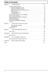
... Flowchart 57 Removing the HDD Module/FDD Module/RAM Door and Optical Drive 60 Removing the LCD Module/the Power Board and the Keyboard 61 Removing the LCD Module 61 Removing the Power Board and the Keyboard 61 Disassembling the Main Unit 62 Separate the main unit into the logic upper and...
... Flowchart 57 Removing the HDD Module/FDD Module/RAM Door and Optical Drive 60 Removing the LCD Module/the Power Board and the Keyboard 61 Removing the LCD Module 61 Removing the Power Board and the Keyboard 61 Disassembling the Main Unit 62 Separate the main unit into the logic upper and...
Aspire 1400 Notebook Service Guide
Page 8
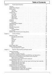
...Diskette Drive Check 70 External CD-ROM Drive Check 70 Keyboard or Auxiliary Input Device Check 71 Memory Check 71 Power System Check 71 Touchpad Check 72 Power-On Self-Test (POST) Error Message 73 Index of Error Messages 74 Index of Symptom-to-FRU Error ...Jumper and Connector Locations 83 SW1 Settings (Lid switch 84 SW2 Settings 84 Bottom View 85 Chapter 6 FRU (Field Replaceable Unit) List 87 Aspire 1400 104 Appendix A Model Definition and Configuration 105 Main Features 105 Appendix B Test Compatible Components 107 Microsoft Windows XP Environment Test 108 Appendix C...
...Diskette Drive Check 70 External CD-ROM Drive Check 70 Keyboard or Auxiliary Input Device Check 71 Memory Check 71 Power System Check 71 Touchpad Check 72 Power-On Self-Test (POST) Error Message 73 Index of Error Messages 74 Index of Symptom-to-FRU Error ...Jumper and Connector Locations 83 SW1 Settings (Lid switch 84 SW2 Settings 84 Bottom View 85 Chapter 6 FRU (Field Replaceable Unit) List 87 Aspire 1400 104 Appendix A Model Definition and Configuration 105 Main Features 105 Appendix B Test Compatible Components 107 Microsoft Windows XP Environment Test 108 Appendix C...

Aspire 1400 Notebook Service Guide
Page 9
... This computer was designed with on-die level 2 cache 256 MB memory expandable to 1G High-capacity, Enhanced-IDE hard disk Lithium-Ion battery pack Power management system Display The large graphics display offers excellent viewing, display quality and desktop-performance graphics. ! Thin-Film Transistor (TFT) liquid-crystal display (LCD) displaying...
... This computer was designed with on-die level 2 cache 256 MB memory expandable to 1G High-capacity, Enhanced-IDE hard disk Lithium-Ion battery pack Power management system Display The large graphics display offers excellent viewing, display quality and desktop-performance graphics. ! Thin-Film Transistor (TFT) liquid-crystal display (LCD) displaying...
Aspire 1400 Notebook Service Guide
Page 15
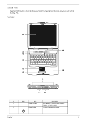
Chapter 1 9 Outlook View A general introduction of ports allow you to connect peripheral devices, as you would with a desktop PC. Front View # Icon Item Description 1 Display screen Also called LCD (liquid-crystal display), displays computer output. 2 Power button Turns on the computer power..
Chapter 1 9 Outlook View A general introduction of ports allow you to connect peripheral devices, as you would with a desktop PC. Front View # Icon Item Description 1 Display screen Also called LCD (liquid-crystal display), displays computer output. 2 Power button Turns on the computer power..

Aspire 1400 Notebook Service Guide
Page 21
Scroll Lock is on. Status indicators Power Lights when the computer is activated. Num lock Scroll lock Numeric Lock (for embedded keypad) is running on AC power. B. AC power Computer is activated. Indicators The computer has easy-to-read lock indicators (A) found above the keyboard, and status indicators (B) and Audio DJ mode indicators (C) on the front panel of the ocmpouter and its components.. Icon A. The status LCD displays icons that show the status of the computer. Lock indicators Function Caps lock Description Caps Lock is activated. Chapter 1 15
Scroll Lock is on. Status indicators Power Lights when the computer is activated. Num lock Scroll lock Numeric Lock (for embedded keypad) is running on AC power. B. AC power Computer is activated. Indicators The computer has easy-to-read lock indicators (A) found above the keyboard, and status indicators (B) and Audio DJ mode indicators (C) on the front panel of the ocmpouter and its components.. Icon A. The status LCD displays icons that show the status of the computer. Lock indicators Function Caps lock Description Caps Lock is activated. Chapter 1 15
Aspire 1400 Notebook Service Guide
Page 32
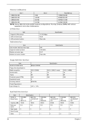
... Specification Floppy Disk Drive Interface Item Vendor & model name Floppy Disk Specifications Media recognition Sectors/track Tracks Rotational speed (RPM) Read/write heads Encoding method Power Requirement Input Voltage (V) Mitsumi D353G 2DD (720KB) 9 80 300 2 MFM/FM +5V +/- 10% Specification 2HD (1.2MB, 3-mode) 15 80 360 2HD (1.44MB) 18 80 300...
... Specification Floppy Disk Drive Interface Item Vendor & model name Floppy Disk Specifications Media recognition Sectors/track Tracks Rotational speed (RPM) Read/write heads Encoding method Power Requirement Input Voltage (V) Mitsumi D353G 2DD (720KB) 9 80 300 2 MFM/FM +5V +/- 10% Specification 2HD (1.2MB, 3-mode) 15 80 360 2HD (1.44MB) 18 80 300...
Aspire 1400 Notebook Service Guide
Page 33
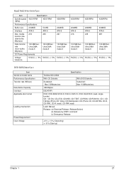
...(DC) +/- 5% 5V(DC) +/- 5% DVD-ROM Interface Item Vendor & model name Performance Specification Transfer rate (KB/sec) Data Buffer Capacity Interface Applicable disc format Loading mechanism Power Requirement Input Voltage Specification Toshiba SD-C2502 With CD Diskette With DVD Diskette Sustained: Max 3.6Mbytes/sec Sustained: Max 10.8Mbytes/sec 128 KBytes IDE...
...(DC) +/- 5% 5V(DC) +/- 5% DVD-ROM Interface Item Vendor & model name Performance Specification Transfer rate (KB/sec) Data Buffer Capacity Interface Applicable disc format Loading mechanism Power Requirement Input Voltage Specification Toshiba SD-C2502 With CD Diskette With DVD Diskette Sustained: Max 3.6Mbytes/sec Sustained: Max 10.8Mbytes/sec 128 KBytes IDE...

Aspire 1400 Notebook Service Guide
Page 37
Electrical Characteristics No . power 6 Efficiency η 80% -- 7 Starting Vs voltage 1500 -- 8 Starting Tvs 1 -- A 6.6 mA 60KHz KHz 4.5 W -- -- --- Parameter Symbol Min. Max. time 9 Dispoff# 2.8 3.3 0 0.5 10 Limited DAC- 0 lamp BRIG maximum current ...
Electrical Characteristics No . power 6 Efficiency η 80% -- 7 Starting Vs voltage 1500 -- 8 Starting Tvs 1 -- A 6.6 mA 60KHz KHz 4.5 W -- -- --- Parameter Symbol Min. Max. time 9 Dispoff# 2.8 3.3 0 0.5 10 Limited DAC- 0 lamp BRIG maximum current ...
Aspire 1400 Notebook Service Guide
Page 40
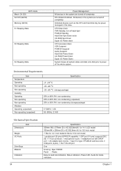
...VGA Standby, turn off back-light PCMCIA Standby Hard Disk Spin Down motor CD-ROM Spin Down Super I/O Power down CPU set power down VGA Suspend PCMCIA Suspend Audio Suspend Hard Disk Power Down CD-ROM Power Down Super I /O Ports Drive Bays Material Indicators 34 Specification 329mm (W) x 279mm (D) x 42.3/52.8mm...in the system are turned off completely. Off (G3) Soft Off (G2/S5) Working (G0/S0) S1 Sleeping State S3 Sleeping State S4 Sleeping State Power Management All devices in port, 1 headphone-out with SPDIF port, 1 AC adapter jack (2 pins), 1 type III or type II PCMCIA card bus slots...
...VGA Standby, turn off back-light PCMCIA Standby Hard Disk Spin Down motor CD-ROM Spin Down Super I/O Power down CPU set power down VGA Suspend PCMCIA Suspend Audio Suspend Hard Disk Power Down CD-ROM Power Down Super I /O Ports Drive Bays Material Indicators 34 Specification 329mm (W) x 279mm (D) x 42.3/52.8mm...in the system are turned off completely. Off (G3) Soft Off (G2/S5) Working (G0/S0) S1 Sleeping State S3 Sleeping State S4 Sleeping State Power Management All devices in port, 1 headphone-out with SPDIF port, 1 AC adapter jack (2 pins), 1 type III or type II PCMCIA card bus slots...
Aspire 1400 Notebook Service Guide
Page 44
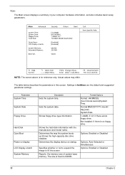
... the memory size of your computer hardware information, and also includes basic setup parameters. Parameter System Time System Date Floppy Drive Hard Disk Quiet Boot Power on startup. Shows floppy drive type information. Not installed: If there is no floppy drive.
... the memory size of your computer hardware information, and also includes basic setup parameters. Parameter System Time System Date Floppy Drive Hard Disk Quiet Boot Power on startup. Shows floppy drive type information. Not installed: If there is no floppy drive.

Aspire 1400 Notebook Service Guide
Page 51
Determines whether or not the system will alarm when the display cover is low. Options Enabled or Disabled Enabled or Disabled Disabled or Enabled Chapter 2 45 Settings in this screen. The table below describes the parameters in boldface are the default and suggested parameter settings. Determines whether or not the system will alarm when the battery power is closed. Others The Others screen contains various parameter settings. Parameter Low Battery Alarm Panel Close Alarm System Beep Description Determines whether or not the system will emit a beep on boot up.
Determines whether or not the system will alarm when the display cover is low. Options Enabled or Disabled Enabled or Disabled Disabled or Enabled Chapter 2 45 Settings in this screen. The table below describes the parameters in boldface are the default and suggested parameter settings. Determines whether or not the system will alarm when the battery power is closed. Others The Others screen contains various parameter settings. Parameter Low Battery Alarm Panel Close Alarm System Beep Description Determines whether or not the system will emit a beep on boot up.
Aspire 1400 Notebook Service Guide
Page 54
... 2 Please contact your regional office MAY have a crisis recovery diskette at hand, then you should create a Crisis Recovery Diskette before you use for Aspire 1400 is not exactly the same as a basic diagnostic tool. Please pay attention to update the system BIOS flash ROM. NOTE: Do not install ... features or options ! NOTE: If you may not boot the system because the BIOS is provided by Acer Headquarters. NOTE: Please use the Phlash. If the battery pack does not contain enough power to the bootable diskette. 3. Copy the Phlash utilities to finish BIOS flash, you do not have other...
... 2 Please contact your regional office MAY have a crisis recovery diskette at hand, then you should create a Crisis Recovery Diskette before you use for Aspire 1400 is not exactly the same as a basic diagnostic tool. Please pay attention to update the system BIOS flash ROM. NOTE: Do not install ... features or options ! NOTE: If you may not boot the system because the BIOS is provided by Acer Headquarters. NOTE: Please use the Phlash. If the battery pack does not contain enough power to the bootable diskette. 3. Copy the Phlash utilities to finish BIOS flash, you do not have other...
Aspire 1400 Notebook Service Guide
Page 55
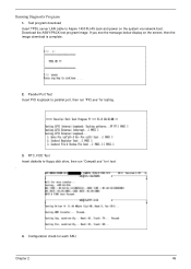
Download the ASSY/PACK test program image. If you see the message below display on the system via network boot. RTC, FDD Test Insert diskette to floppy disk drive, then run "PIO.exe" for testing. 3. Configuration check for t test. . 4. Test program download Insert TPDL server LAN cable to parallel port, then run "Compalt.exe" for each SKU Chapter 2 49 Running Diagnostic Program 1. Parallel Port Test Insert PIO loopback to Aspire 1400 RJ-45 Jack and power on the screen, then the image download is complete. 2.
Download the ASSY/PACK test program image. If you see the message below display on the system via network boot. RTC, FDD Test Insert diskette to floppy disk drive, then run "PIO.exe" for testing. 3. Configuration check for t test. . 4. Test program download Insert TPDL server LAN cable to parallel port, then run "Compalt.exe" for each SKU Chapter 2 49 Running Diagnostic Program 1. Parallel Port Test Insert PIO loopback to Aspire 1400 RJ-45 Jack and power on the screen, then the image download is complete. 2.
Aspire 1400 Notebook Service Guide
Page 62
... Before You Begin Before proceeding with the disassembly procedure, make sure you do the following: 1. Remove the battery pack. 4. Otherwise, other screws that secure the power board LS-1257 on the upper case are too long may need to tear the tape or mylar before you secure the... case. The two screws that are M2.5x4. Turn off the power to fasten the FFC/FPC/connectors/cable, you may damage the main board as you disconnect different FFC/FPC/connectors. 56 Chapter 3 NOTE: Aspire 1400 uses mylar or tape to the system and all power and signal cables from the system. 3.
... Before You Begin Before proceeding with the disassembly procedure, make sure you do the following: 1. Remove the battery pack. 4. Otherwise, other screws that secure the power board LS-1257 on the upper case are too long may need to tear the tape or mylar before you secure the... case. The two screws that are M2.5x4. Turn off the power to fasten the FFC/FPC/connectors/cable, you may damage the main board as you disconnect different FFC/FPC/connectors. 56 Chapter 3 NOTE: Aspire 1400 uses mylar or tape to the system and all power and signal cables from the system. 3.
Aspire 1400 Notebook Service Guide
Page 63
... Panasoni: Ex2 MIT: GX2 FDD Panel Ex4 RAM Door Ex2 Antenna Covers Wireless LAN Card Ex1 Optical Drive Optical Panel Ax2 Optical Bracket Ex2 LED power board LS- 1257 Stripe Cover Disconenct Keyboard FFC Ex2 Keyboard Ex1 EMI Bar Disconnect coaxial cable Fx4 LCD Module Ex2 LCD Bezel Ex6 Dx2 Ex1...
... Panasoni: Ex2 MIT: GX2 FDD Panel Ex4 RAM Door Ex2 Antenna Covers Wireless LAN Card Ex1 Optical Drive Optical Panel Ax2 Optical Bracket Ex2 LED power board LS- 1257 Stripe Cover Disconenct Keyboard FFC Ex2 Keyboard Ex1 EMI Bar Disconnect coaxial cable Fx4 LCD Module Ex2 LCD Bezel Ex6 Dx2 Ex1...
Aspire 1400 Notebook Service Guide
Page 67
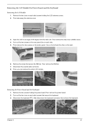
Removing the LCD Module/the Power Board and the Keyboard Removing the LCD Module 1. Then remove the strip cover (middle cover). 4. Then remove the two screws on the right. 6. Turn out ..., you can remove the entire LCD module. Then remove the EMI bar. 7. Remove the two (one on each side) screws holding the power board.Then remove the power board. 2. Removing the Power Board and the Keyboard 1. Remove the two screws holding the LCD antenna covers. 2. Then take away the antenna cover. 3. After disconnect...
Removing the LCD Module/the Power Board and the Keyboard Removing the LCD Module 1. Then remove the strip cover (middle cover). 4. Then remove the two screws on the right. 6. Turn out ..., you can remove the entire LCD module. Then remove the EMI bar. 7. Remove the two (one on each side) screws holding the power board.Then remove the power board. 2. Removing the Power Board and the Keyboard 1. Remove the two screws holding the LCD antenna covers. 2. Then take away the antenna cover. 3. After disconnect...
Aspire 1400 Notebook Service Guide
Page 75
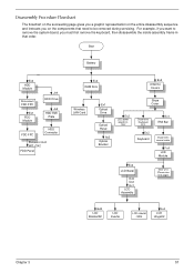
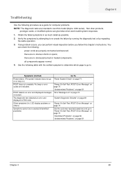
...and go to . Use the following : power cords are properly connected and secured; Other symptoms (i.e. Chapter 4 Troubleshooting Use the following procedure as possible. 2. You can perform visual inspection before you fellow this model (Aspire 1400 series). If any problem occurs, you.... Symptoms cannot be re-created (intermittent problems). Non-Acer products, prototype cards, or modified options can give false errors and invalid system responses. 1. Symptoms (Verified) Power failure. (The power indicator does not go to "Power-On Self-Test (POST) Error Message" on page 73...
...and go to . Use the following : power cords are properly connected and secured; Other symptoms (i.e. Chapter 4 Troubleshooting Use the following procedure as possible. 2. You can perform visual inspection before you fellow this model (Aspire 1400 series). If any problem occurs, you.... Symptoms cannot be re-created (intermittent problems). Non-Acer products, prototype cards, or modified options can give false errors and invalid system responses. 1. Symptoms (Verified) Power failure. (The power indicator does not go to "Power-On Self-Test (POST) Error Message" on page 73...
Aspire 1400 Notebook Service Guide
Page 77
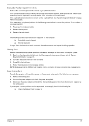
... installed into the connector. Reconnect the keyboard cables. 2. Embedded numeric keypad ! External keyboard If any of these devices do the following power sources: 1. Follow the instructions in the test items. 4. NOTE: Make sure that the flexible cable extending from the diagnostics diskette and... start the doagmpstotics program (please refer to be tested. Power System Check To verify the symptom of the following one at a time to the diagnostic memory in the following auxiliary input devices...
... installed into the connector. Reconnect the keyboard cables. 2. Embedded numeric keypad ! External keyboard If any of these devices do the following power sources: 1. Follow the instructions in the test items. 4. NOTE: Make sure that the flexible cable extending from the diagnostics diskette and... start the doagmpstotics program (please refer to be tested. Power System Check To verify the symptom of the following one at a time to the diagnostic memory in the following auxiliary input devices...
Aspire 1400 Notebook Service Guide
Page 78
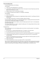
... screen for both battery and adapter. 4. No service actions are necessary if the pointer movement stops in a short period of the total power remaining when installed in the computer. In Power Meter, confirm that has less than 7.5 Vdc after recharging, replace the battery. This helps you use a discharged battery pack or a battery... Pad PS2 Mode Driver. Replace switch board. 7. If the main board to the touchpad pointer. Repeat the steps 1 and 2, for a short time. Check out the Power Management in the screen for Current Power Source and Total Battery Power Remaining are pulese.
... screen for both battery and adapter. 4. No service actions are necessary if the pointer movement stops in a short period of the total power remaining when installed in the computer. In Power Meter, confirm that has less than 7.5 Vdc after recharging, replace the battery. This helps you use a discharged battery pack or a battery... Pad PS2 Mode Driver. Replace switch board. 7. If the main board to the touchpad pointer. Repeat the steps 1 and 2, for a short time. Check out the Power Management in the screen for Current Power Source and Total Battery Power Remaining are pulese.

Aspire 1400 Notebook Service Guide
Page 79
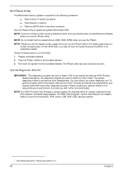
... that the BIOS displays on page 81. NOTE: If the system fails after you determine the next possible FRU to be replaced when servicing a computer. Power-On Self-Test (POST) Error Message The POST error message index lists the error message and their possible causes. Some of them display information about...
... that the BIOS displays on page 81. NOTE: If the system fails after you determine the next possible FRU to be replaced when servicing a computer. Power-On Self-Test (POST) Error Message The POST error message index lists the error message and their possible causes. Some of them display information about...


