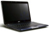
Acer Aspire 1410 and Aspire 1680 Service Guide
Page 7
...312004 Shipping priority Quanta Named Project Name Platform naming M/B Chipset CPU LCD VGA Console display Arcade windows mode Optical Hot swapple HDD wireless WNC Bluetooth Battery Life Battery cell Port replicator LAN Card reader Smart card DASP Keyboard Subwoofer SPDIF OS Driver support Disk to Disk NB manager 2 weight No. 5 Kestrel...SXGA+(tender) ATI 9700 with 64MB NO NO Combo DVD-SuperMulti DVD-Dual 2nd HDD, 2nd battery, weight saver 40GB / 60GB / 80GB UMA NO NO Combo DVD-SuperMulti DVD-Dual 2nd HDD, 2nd battery, weight saver 40GB / 60GB / 80GB ATI 9700 with 64MB NO NO Combo DVD-Dual ...
Acer Aspire 1410 and Aspire 1680 Service Guide
Page 8
Table of Contents Chapter 1 System Introduction 1 Features 1 System Block Diagram 3 Board Layout 4 Top View 4 Bottom View 5 An Aspire Tour 7 Front View 7 Closed Front View 8 Left View 9 Right View 10 Rear Panel 11 Bottom Panel 12 Indicators 13 Using the Keyboard 15 Lock ... 48 BIOS Flash Utility 49 Chapter 3 Machine Disassembly and Replacement 50 General Information 51 Before You Begin 51 Disassembly Procedure Flowchart 53 Removing the Battery Pack 55 Removing the HDD Module/the Memory and the Wireless LAN Card/the Thermal Module and the CPU/ODD Module and LCD Module 56...
Acer Aspire 1410 and Aspire 1680 Service Guide
Page 11
T Internal removable optical drive (AcerMedia bay) T Li-ion main battery pack Display T T T T T T The TFT LCD panel providing a lare viewing area for maximum efficiency and ease-of video memory (manufacturing option) 3D graphics support Simultaneous display ...
Acer Aspire 1410 and Aspire 1680 Service Guide
Page 13
...4 5 6 SYSTEM 3 DOCKING 2 MINI-USB USB PORT USB PORT Page : 15 Page : 15 Page: 15 D USB2,3,5 USB0,1 USB4 PROJECT:Kestrel Series Acer Incorporated Size Document Number BLOCK DIAGRAM Date: Friday, June 04, 2004 7 Sheet 1 of 8 Rev A1A 35 Chapter 1 3 1 2 5VPCU 5V / ...2V B Page : 10 1.5V_S5 +1.5V AGP_VCC (+1.5V) 1.2VCCT VTT CPU CORE Page : 10 VCC_CORE VGA_CORE VGA CORE/VRAM 2.5V_VGA Page : 10 BATTERY C CHARGER Page : 10 BATTERY SELECT Page : 10 3 4 5 6 7 8 CLOCK GEN CYPRESS CY28346-2 Page : 10 Centrino BANIAS DORTHAN CELEROM-M CLOCK S/S INTEL Mobile_479 CPU Page ...
Acer Aspire 1410 and Aspire 1680 Service Guide
Page 18
NOTE: The Bluetooth and Wireless buttons and indicators only work on . 4 Battery indicator Lights when the battery is being charged 5 Bluetooth® Indicates that (optional) Bluetooth is communications enabled. 6 Wireless Indicates status of wireless LAN communi- communication cation. 7 Line-in/Mic-in ...
Acer Aspire 1410 and Aspire 1680 Service Guide
Page 22
Note: Do not cover or obstruct the opening of the fan. 2 Battery lock Locks the battery in place. 3 Memory compartment Houses the computer's main memory. 4 Hard disk bay Houses the computer's hard disk (secured by a screw). 6 Battery release latch Unlatches the battery to remove the battery pack. 7 Battery bay Houses the computer's battery pack. 12 Chapter 1 Bottom Panel # Item Description 1 Cooling fan Helps keep the computer cool.
Acer Aspire 1410 and Aspire 1680 Service Guide
Page 24
In addition, there are two indicators at the front panel. Icon Function Power Description Lights when the computer is being charged. 14 Chapter 1 Battery indicator Lights when the battery is on. Even when the cover is closed, the state or features can still be seen.
Acer Aspire 1410 and Aspire 1680 Service Guide
Page 41
Plug USB keyboard to the USB port/PS 2 port on the port replicator: Yes Battery Item Vendor & model name Battery Type Pack capacity Number of battery cell Package configuration Normal voltage Charge voltage Specification Sanyo 4UR18650F-2-QC140 Panasonic CGR-B/8B5AE Simplo 916-3020 Li-ion 4400 mAh...directly: Yes 2. System Board Major Chips Item Wireless 802.11 b+g PCMCIA Audio 3-in parallel 14.4V 16.8+-0.2v LCD 14.1 inch for Aspire 1410 Item Vendor & model name Screen Diagonal (mm) Active Area (mm) Display resolution (pixels) Pixel Pitch Pixel Arrangement Display Mode Typical White ...
Acer Aspire 1410 and Aspire 1680 Service Guide
Page 50
.../YYYY (month/day/ year) System Date This field reports the memory size of the LCD backlight when the AC power is connected, the power on battery power). Enabled: Customer Logo is displayed, and Summary Screen is disabled or enabled. shows Summary Screen is disabled. Both: Simultaneously enable both the integrated LCD...
Acer Aspire 1410 and Aspire 1680 Service Guide
Page 59
...: If you do not have a crisis recovery diskette at hand, then you should create a Crisis Recovery Diskette before you use the Phlash utility. If the battery pack does not contain enough power to run the Phlash utility. Prepare a bootable diskette. 2. The Phlash utility has auto-execution function. 49 Chapter 2 Then boot...
Acer Aspire 1410 and Aspire 1680 Service Guide
Page 61
... for service purpose. Turn off the power to secure bottom case and upper case are inside the system. Remove the battery pack. You may have to see these screws. IO Bezel Battery The screws that secure heatsink cover, MIni PCI cover and HDD cover are with the disassembly procedure, make sure that...
Acer Aspire 1410 and Aspire 1680 Service Guide
Page 62
Detach the HDD module 1 then you 1 will see. Remove the battery then you will see. Remove the HDD cover then 1 you will see. Remove the heatsink cover 1 then you will see. Quantity Chapter 3 52 Screw Type M2.5*6 M2.5*6 M2.5*6 M2.5*6 M2.5*3 M2.5*3 Location Bottom case and IO bezel 14 (hightlight with yellow circle) Remove the IO bezel then 2 you will see.
Acer Aspire 1410 and Aspire 1680 Service Guide
Page 63
... want to be removed during servicing. Disassembly Procedure Flowchart The flowchart on the succeeding page gives you a graphic representation on the components that order. Start Battery K*2 HDD Cover HDD Module E*2 RAM/Wireless Cover Wireless LAN Card Memory CPU *2 IO Bezel *2 Heatsink Cover *2 Thermal Module ODD Module *6 ODD Connector Board ODD Holder...
Acer Aspire 1410 and Aspire 1680 Service Guide
Page 65
Unlock the battery lock. 2. Slide the battery latch as shown then remove the battery pack. 55 Chapter 3 Removing the Battery Pack 1.
Acer Aspire 1410 and Aspire 1680 Service Guide
Page 80
...not work, reconnect the cable connector and repeat the failing operation. Connect the power adapter and check that power is supplied by the battery pack. Follow the instructions in the following power sources: 1. then check that power is fully installed into the connector. If you suspect...the appropriate power supply check in the message window. Press F2 in the test items. 3. Remove the battery pack. 2. Disconnect the power adapter and install the charged battery pack; Boot from the diagnostics diskette and start the doagmpstotics program (please refer to the diagnostic memory in ...
Acer Aspire 1410 and Aspire 1680 Service Guide
Page 81
T If the voltage is not corrected, see "Check the Battery Pack" on indicator does not light up, check the power cord of the power adapter cable. NOTE: An audible noise from the computer and measure ...
Acer Aspire 1410 and Aspire 1680 Service Guide
Page 82
...slight, steady pressure is on the screen for a short time. Chapter 4 72 Repeat the steps 1 and 2, for Current Power Source and Total Battery Power Remaining are necessary if the pointer movement stops in control Panel 2. Touchpad Check If the touchpad doesn't work, do the following figure 3. Replace...installed in the computer. If the voltage is not a hardware problem. If the charge indicator still does not light up , remove the battery pack and let it return to room temperature. After you identify first the problem is applied to correct the problem. This helps you ...
Acer Aspire 1410 and Aspire 1680 Service Guide
Page 84
...DIMM System board Extended RAM Failed at xxxx:xxxx:xxxxh (R:xxxxh, W:xxxxh) Real Time Clock Error CMOS Battery Bad CMOS Checksum Error System disabled. Default configuration used RTC battery Run BIOS Setup Utility to reconfigure system time, then reboot system. System board Chapter 4 74 Index of... show message. Hard disk drive System board Stuck Key see "Keyboard or Auxiliary Input Device Check" on page 69. Keyboard locked - Battery critical LOW In this situation BIOS will shut down system, no message will be shown before "Equipment Configuration Error") Memory Error at offset...
Acer Aspire 1410 and Aspire 1680 Service Guide
Page 85
... None Invalid System Configuration Data BIOS ROM System board I/O device IRQ conflict Run "Load Default Settings" in BIOS Setup Utility. RTC battery System board Operating system not found by POST differed from CMOS Run "Load Default Settings" in BIOS Setup Utility. Error Message List ...Error Messages FRU/Action in BIOS Setup Utility. Default configuration used Run "Load Default Settings" in Sequence Real time clock error RTC battery Run BIOS Setup Utility to reconfigure system time, then reboot system. Incorrect Drive A type - Cache disabled System board CPU ID: ...
Acer Aspire 1410 and Aspire 1680 Service Guide
Page 86
... and correctly. See "Power System Check" on an external CRT. But you can see POST on page 70. Ensure every connector is blank. Power source (battery pack and power adapter). Reconnect the LCD connector Hard disk drive LCD inverter ID LCD cable LCD Inverter LCD System board No beep, power-on... inverter LCD System board No beep, power-on indicator turns on and a blinking cursor shown on and LCD is connected tightly and correctly. Power source (battery pack and power adapter). System board. LED board. System board No beep during POST. Speaker System board Chapter 4 76