
AL511 Service Guide
Page 1
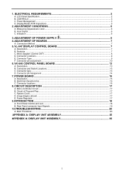
... ...7 C. POWER BOARD...15 A. Circuit of Plug and Play ...17 C. Image Engine (Zoom)...17 E. Rear Panel connector Input Signals ...19 10.TROUBLESHOOTING 20 A. CONTROLS ...3 C. Connector Locations...9 E. LCD Panel Specification...2 B. Power Management ...3 D. Measuring Apparatuses Used ...6 B. Indication ...6 3. ADJUSTMENT OF POWER SUPPLY 6 4. ADJUSTMENT OF BOARDS 7 A. VL-547 DISPLAY CONTROL BOARD 7 A. Connector Type ...9 F. VK-546 CONTROL...
... ...7 C. POWER BOARD...15 A. Circuit of Plug and Play ...17 C. Image Engine (Zoom)...17 E. Rear Panel connector Input Signals ...19 10.TROUBLESHOOTING 20 A. CONTROLS ...3 C. Connector Locations...9 E. LCD Panel Specification...2 B. Power Management ...3 D. Measuring Apparatuses Used ...6 B. Indication ...6 3. ADJUSTMENT OF POWER SUPPLY 6 4. ADJUSTMENT OF BOARDS 7 A. VL-547 DISPLAY CONTROL BOARD 7 A. Connector Type ...9 F. VK-546 CONTROL...
AL511 Service Guide
Page 2
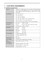
...: 25W on mode +10 / -25% Environmental: Operating temperature: 0ºC to 50ºC Storage temperature: -20ºC to 60ºC Storage humidity: 10%~90% 2 ELECTRICAL REQUIREMENTS A. LCD Panel Specification Display: 15 inch (15" viewable image size): active matrix: thin film transistor (TFT): liquid crystal display...
...: 25W on mode +10 / -25% Environmental: Operating temperature: 0ºC to 50ºC Storage temperature: -20ºC to 60ºC Storage humidity: 10%~90% 2 ELECTRICAL REQUIREMENTS A. LCD Panel Specification Display: 15 inch (15" viewable image size): active matrix: thin film transistor (TFT): liquid crystal display...

AL511 Service Guide
Page 3
... Suspend Pulses No Pulses Off No pulses No pulses Blacking On DC Power off Don't care Don't care Don't care Off Video Circuit On Off LCD On Off Off Off LED Green Yellow Yellow Off 3 Adjust increase 4. B. Power ON/OFF switch, push to ON and push to C-2 LED definition table) 2. Function...
... Suspend Pulses No Pulses Off No pulses No pulses Blacking On DC Power off Don't care Don't care Don't care Off Video Circuit On Off LCD On Off Off Off LED Green Yellow Yellow Off 3 Adjust increase 4. B. Power ON/OFF switch, push to ON and push to C-2 LED definition table) 2. Function...
AL511 Service Guide
Page 7
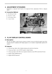
... user functions. • Using sage chip to convert R.G.B signals to digital timing • Using sage chip to construct a high display quality LCD monitor. Connection Method 1. Refer to be inspected before adjustments. B. 4. R.G.B Signal Cable 2. ADJUSTMENT OF BOARDS Equipment is design to directly convert... the R.G.B signals from VGA Card D-sub port to optimum LCD timing signals so as to offer full screen expansion function on non-XGA mode(Auto-Zoom). • Support VESA DPMS function. •...
... user functions. • Using sage chip to convert R.G.B signals to digital timing • Using sage chip to construct a high display quality LCD monitor. Connection Method 1. Refer to be inspected before adjustments. B. 4. R.G.B Signal Cable 2. ADJUSTMENT OF BOARDS Equipment is design to directly convert... the R.G.B signals from VGA Card D-sub port to optimum LCD timing signals so as to offer full screen expansion function on non-XGA mode(Auto-Zoom). • Support VESA DPMS function. •...
AL511 User Guide
Page 1
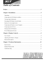
Table of Contents Preface ...2 Chapter 1 Installation 4 Unpacking ...4 Connecting the LCD Monitor and Base 4 Viewing Angle Adjustment ...4 Detaching LCD Monitor from Its Stand 5 Interface for Arm Applications 5 Connecting the Display to your Computer 5 Connecting the AC Power...7 Setting Up the LCD Monitor...7 Power Management System...7 Chapter 2 Display Controls 8 User Controls ...8 Adjusting the Monitor's Display 8 Function Description...10 Chapter 3 Technical Information 12 Specifications...12 Standard Timing Table ...15 Troubleshooting...17
Table of Contents Preface ...2 Chapter 1 Installation 4 Unpacking ...4 Connecting the LCD Monitor and Base 4 Viewing Angle Adjustment ...4 Detaching LCD Monitor from Its Stand 5 Interface for Arm Applications 5 Connecting the Display to your Computer 5 Connecting the AC Power...7 Setting Up the LCD Monitor...7 Power Management System...7 Chapter 2 Display Controls 8 User Controls ...8 Adjusting the Monitor's Display 8 Function Description...10 Chapter 3 Technical Information 12 Specifications...12 Standard Timing Table ...15 Troubleshooting...17

AL511 User Guide
Page 2
... in a particular installation. No part of the contents. All rights are designed to provide reasonable protection against harmful interference in setting up and using the LCD Monitor. Preface This manual is designed to assist users in a residential installation.
... in a particular installation. No part of the contents. All rights are designed to provide reasonable protection against harmful interference in setting up and using the LCD Monitor. Preface This manual is designed to assist users in a residential installation.
AL511 User Guide
Page 3
... power supply type: Li-shin, LSE 9802A1240 3 Do not apply pressure to the display. 4. Excess pressure may cause permanent damage to the LCD screen. For a nominal current up to service this unit by an authorized technician. 5. Cet appareil numérique de la classe B repecte...of any of the Canadian Interference-Causing Equipment Regulations. ENGLISH This Class B digital apparatus meets all requirements of the following instructions carefully. Power off LCD Monitor and unplug the AC Cord. -- Do not remove the cover or attempt to 6A and a device weight above 3 kg, a line ...
... power supply type: Li-shin, LSE 9802A1240 3 Do not apply pressure to the display. 4. Excess pressure may cause permanent damage to the LCD screen. For a nominal current up to service this unit by an authorized technician. 5. Cet appareil numérique de la classe B repecte...of any of the Canadian Interference-Causing Equipment Regulations. ENGLISH This Class B digital apparatus meets all requirements of the following instructions carefully. Power off LCD Monitor and unplug the AC Cord. -- Do not remove the cover or attempt to 6A and a device weight above 3 kg, a line ...
AL511 User Guide
Page 4
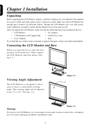
...be adjusted from -5°t o +35°. (See fig. 1-2) Figure 1-1 Warning Figure 1-2 Do not force the LCD Monitor over its maximum viewing angle settings as stated above. After you unpack the LCD Monitor, make sure that the following items were included in damaging the Monitor and Monitor stand. 4 Attempting this...-to-PC signal Cable * 1.8M Power Cord * User's Manual * Base If you open the box to have a comfortable viewing angle. Though the LCD Monitor uses very little power, some ventilation is needed to ensure that any of these items is designed to allow users to take the base...
...be adjusted from -5°t o +35°. (See fig. 1-2) Figure 1-1 Warning Figure 1-2 Do not force the LCD Monitor over its maximum viewing angle settings as stated above. After you unpack the LCD Monitor, make sure that the following items were included in damaging the Monitor and Monitor stand. 4 Attempting this...-to-PC signal Cable * 1.8M Power Cord * User's Manual * Base If you open the box to have a comfortable viewing angle. Though the LCD Monitor uses very little power, some ventilation is needed to ensure that any of these items is designed to allow users to take the base...

AL511 User Guide
Page 5
... the VESA Flat Panel Monitor Physical Mounting Interface Standard (paragraphs 2.1 and 2.1.3, version 1, dated 13 November 1997). Connect the other end of this LCD display has four integrated 4 mm, 0.7 pitches threaded nuts, as well as four 5 mm access holes in the plastic covering as illustrated in... ferrite-core interface cable is 5 Power off -the-shelf video cable in Figure 1-4. Figure 1-5 Attention This device must be in the LCD Monitor package. Unscrew screws of the signal cable to comply with FCC regulations when a non-ferrite-core video cable is included in compliance ...
... the VESA Flat Panel Monitor Physical Mounting Interface Standard (paragraphs 2.1 and 2.1.3, version 1, dated 13 November 1997). Connect the other end of this LCD display has four integrated 4 mm, 0.7 pitches threaded nuts, as well as four 5 mm access holes in the plastic covering as illustrated in... ferrite-core interface cable is 5 Power off -the-shelf video cable in Figure 1-4. Figure 1-5 Attention This device must be in the LCD Monitor package. Unscrew screws of the signal cable to comply with FCC regulations when a non-ferrite-core video cable is included in compliance ...
AL511 User Guide
Page 7
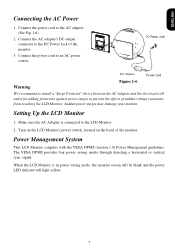
... the AC Adapter and the electrical wall outlet for adding protection against power surges to the AC adapter. (See Fig. 1-6) 2. Turn on the LCD Monitor's power switch, located on the bezel of the monitor. 3. Connect the power cord to prevent the effects of sudden voltage variations from reaching ...the LCD Monitor. Connect the AC adapter's DC output connector to an AC power source. signal. Connect the power cord to the DC Power Jack ...
... the AC Adapter and the electrical wall outlet for adding protection against power surges to the AC adapter. (See Fig. 1-6) 2. Turn on the LCD Monitor's power switch, located on the bezel of the monitor. 3. Connect the power cord to prevent the effects of sudden voltage variations from reaching ...the LCD Monitor. Connect the AC adapter's DC output connector to an AC power source. signal. Connect the power cord to the DC Power Jack ...
AL511 User Guide
Page 8
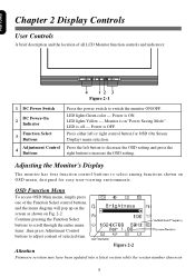
... on Fig. 2-2: Continue pressing the Function Select buttons to scroll through the entire menu items ,then press Adjustment Control buttons to adjust content of all LCD Monitor function controls and indicators: Figure 2-1 1 DC Power Switch DC Power-On 2 Indicator 3 Function Select Buttons 4 Adjustment Control Buttons Press the power switch to switch...
... on Fig. 2-2: Continue pressing the Function Select buttons to scroll through the entire menu items ,then press Adjustment Control buttons to adjust content of all LCD Monitor function controls and indicators: Figure 2-1 1 DC Power Switch DC Power-On 2 Indicator 3 Function Select Buttons 4 Adjustment Control Buttons Press the power switch to switch...
AL511 User Guide
Page 12
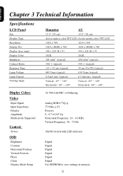
Chapter 3 Technical Information Specifications LCD Panel Size Display Type Resolution Display Dot Display Area (mm) Display Color Brightness Contrast Ratio Response Time Lamp Voltage Lamp Current Viewing Angle Display Colors ... Brightness Contrast Horizontal Position Vertical Position Phase Clock Display Mode Setup Hannstar AU 15.0" (38 cm) 15.0" (38 cm) Active matrix color TFT LCD Active matrix color TFT LCD 1024 x 768 1024 x 768 1024 x (RGB) x 768 1024 x (RGB) x 768 304 x 228 (H x V) 304 x 228 (H x V) 262K 200 cd/m2 (typical) 262K 200 cd/m2...
Chapter 3 Technical Information Specifications LCD Panel Size Display Type Resolution Display Dot Display Area (mm) Display Color Brightness Contrast Ratio Response Time Lamp Voltage Lamp Current Viewing Angle Display Colors ... Brightness Contrast Horizontal Position Vertical Position Phase Clock Display Mode Setup Hannstar AU 15.0" (38 cm) 15.0" (38 cm) Active matrix color TFT LCD Active matrix color TFT LCD 1024 x 768 1024 x 768 1024 x (RGB) x 768 1024 x (RGB) x 768 304 x 228 (H x V) 304 x 228 (H x V) 262K 200 cd/m2 (typical) 262K 200 cd/m2...
AL511 User Guide
Page 15
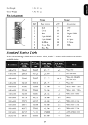
....087 25.175 +/- Sync. 10 7 Green Rtn 15 SCL 8 Blue Rtn Standard Timing Table If the selected timing is NOT included in table below, this LCD monitor will use the most suitable available timing. VESA - 480 - 72Hz 640 x 480 37.500 75.000 31.500 -/- VGA-350 640 x 400 24.830...
....087 25.175 +/- Sync. 10 7 Green Rtn 15 SCL 8 Blue Rtn Standard Timing Table If the selected timing is NOT included in table below, this LCD monitor will use the most suitable available timing. VESA - 480 - 72Hz 640 x 480 37.500 75.000 31.500 -/- VGA-350 640 x 400 24.830...
AL511 User Guide
Page 17
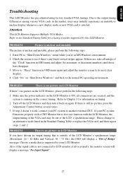
...the monitor screen to an alternative mode listed in OSD menu and adjust (by increment or decrement numbers) until those bars disappear. 3. Refer to LCD monitor at all connections are , take advantage of the "Clock" function in the Standard Timing Table or replace the VGA card, and then repeat...or unclear display whenever a new display mode or new VGA card is running on "Shut Down Windows" and back to Chapter 3 for a listing of the LCD Monitor's synchronous range (Horizontal: 24 ~ 61 KHz and Vertical: 56 ~ 75 Hz), the OSD will display a message "No Input Signal". 17 Please ...
...the monitor screen to an alternative mode listed in OSD menu and adjust (by increment or decrement numbers) until those bars disappear. 3. Refer to LCD monitor at all connections are , take advantage of the "Clock" function in the Standard Timing Table or replace the VGA card, and then repeat...or unclear display whenever a new display mode or new VGA card is running on "Shut Down Windows" and back to Chapter 3 for a listing of the LCD Monitor's synchronous range (Horizontal: 24 ~ 61 KHz and Vertical: 56 ~ 75 Hz), the OSD will display a message "No Input Signal". 17 Please ...


