
AL511 Service Guide
Page 1
...8. Image Engine (Zoom)...17 E. Rear Panel connector Input Signals ...19 10.TROUBLESHOOTING 20 A. LCD Panel Specification...2 B. ADJUSTMENT OF POWER SUPPLY 6 4. Circuit of Plug and Play ...17 C. Power Management ...3 D. Measuring Apparatuses Used ...6 B. ADJUSTMENT OF BOARDS 7 A. Connection Method ...7 5. System Clock...17 D. Power Regulator...17 9. 1. ELECTRICAL REQUIREMENTS 2 A. CONTROLS ...3 C. Display Modes FOR Inspections ...5 2. Input Signal...6 C. VL-547 DISPLAY CONTROL BOARD 7 A. Block Diagram (Control CKT)...8 D. VK-546 CONTROL PANEL BOARD 13...
...8. Image Engine (Zoom)...17 E. Rear Panel connector Input Signals ...19 10.TROUBLESHOOTING 20 A. LCD Panel Specification...2 B. ADJUSTMENT OF POWER SUPPLY 6 4. Circuit of Plug and Play ...17 C. Power Management ...3 D. Measuring Apparatuses Used ...6 B. ADJUSTMENT OF BOARDS 7 A. Connection Method ...7 5. System Clock...17 D. Power Regulator...17 9. 1. ELECTRICAL REQUIREMENTS 2 A. CONTROLS ...3 C. Display Modes FOR Inspections ...5 2. Input Signal...6 C. VL-547 DISPLAY CONTROL BOARD 7 A. Block Diagram (Control CKT)...8 D. VK-546 CONTROL PANEL BOARD 13...
AL511 Service Guide
Page 2
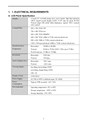
ELECTRICAL REQUIREMENTS A. 1. 1. LCD Panel Specification Display: 15 inch (15" viewable image size): active matrix: thin film transistor (TFT): liquid crystal display (LCD): 0.297 mm dot pitch: R.G.B. Vertical stripe 200 cd//m2 white luminance, typical: 300:1 contrast ratio, typical Compatibility: 640 x 350: VGA-350 720 x 400: VGA text 640 x 400: VGA-GRAPH 640 x 480: VGA, 60Hz to 75 Hz vertical refresh rate 800 x 600: 56Hz to 75 Hz vertical refresh rate Synchronization Frequencies: 1024 x 768 non-interlaced...
ELECTRICAL REQUIREMENTS A. 1. 1. LCD Panel Specification Display: 15 inch (15" viewable image size): active matrix: thin film transistor (TFT): liquid crystal display (LCD): 0.297 mm dot pitch: R.G.B. Vertical stripe 200 cd//m2 white luminance, typical: 300:1 contrast ratio, typical Compatibility: 640 x 350: VGA-350 720 x 400: VGA text 640 x 400: VGA-GRAPH 640 x 480: VGA, 60Hz to 75 Hz vertical refresh rate 800 x 600: 56Hz to 75 Hz vertical refresh rate Synchronization Frequencies: 1024 x 768 non-interlaced...

AL511 Service Guide
Page 3
... Signals Power Horizontal Vertical Video Supply On Pulses Pulses Active On Stand-by No Pulses Pulses Blanking Suspend Pulses No Pulses Off No pulses No pulses Blacking On DC Power off Don't care Don't care Don't care Off Video Circuit On Off LCD On Off Off Off LED Green Yellow Yellow Off 3 Power ON/OFF switch, push to ON and push to C-2 LED definition table) 2. B. Adjust increase 4. CONTROLS B-1 Control panel (monitor...
... Signals Power Horizontal Vertical Video Supply On Pulses Pulses Active On Stand-by No Pulses Pulses Blanking Suspend Pulses No Pulses Off No pulses No pulses Blacking On DC Power off Don't care Don't care Don't care Off Video Circuit On Off LCD On Off Off Off LED Green Yellow Yellow Off 3 Power ON/OFF switch, push to ON and push to C-2 LED definition table) 2. B. Adjust increase 4. CONTROLS B-1 Control panel (monitor...
AL511 Service Guide
Page 4
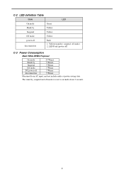
LED Dark (power off) C-3 Power Consumption Meet VESA DPMS Proposal On mode Stand-by Suspend Off mode DC power off mode recover to on mode about 3 seconds. 4 Yellow(stand-by , suspend and off disconnection 25 Wmax 5 Wmax 5 Wmax 5 Wmax 5 Wmax 5 Wmax Measured from AC input, and not include audio at power-saving state The stand-by ; suspend; off disconnection Dark 1. C-2 LED definition Table State LED On mode Green Stand-by Yellow Suspend Yellow Off mode Yellow power off mode) 2.
LED Dark (power off) C-3 Power Consumption Meet VESA DPMS Proposal On mode Stand-by Suspend Off mode DC power off mode recover to on mode about 3 seconds. 4 Yellow(stand-by , suspend and off disconnection 25 Wmax 5 Wmax 5 Wmax 5 Wmax 5 Wmax 5 Wmax Measured from AC input, and not include audio at power-saving state The stand-by ; suspend; off disconnection Dark 1. C-2 LED definition Table State LED On mode Green Stand-by Yellow Suspend Yellow Off mode Yellow power off mode) 2.
AL511 Service Guide
Page 7
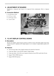
... R.G.B signals from VGA Card D-sub port to optimum LCD timing signals so as to be inspected before adjustments. DC Power Cable 3. Description The VL-547 display control board is connected with boards to construct a high display quality LCD monitor. 4. A. LCD Lamp Cables 4. Control Cable 5. Connection Method 1. R.G.B Signal Cable 2. Features • On board sage chip to detect display timings and control user functions. • Using sage chip to convert R.G.B signals to digital timing • Using sage chip to diagram below. Refer to offer full screen...
... R.G.B signals from VGA Card D-sub port to optimum LCD timing signals so as to be inspected before adjustments. DC Power Cable 3. Description The VL-547 display control board is connected with boards to construct a high display quality LCD monitor. 4. A. LCD Lamp Cables 4. Control Cable 5. Connection Method 1. R.G.B Signal Cable 2. Features • On board sage chip to detect display timings and control user functions. • Using sage chip to convert R.G.B signals to digital timing • Using sage chip to diagram below. Refer to offer full screen...
AL511 Service Guide
Page 12
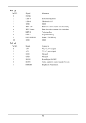
Audio amplifier control signal (No use) Brightness Adjustment. 12 F-3 J2 Pin NO. 1 2 3 4 5 6 7 8 9 10 F-4 J3 Pin NO. 1 2 3 4 5 6 7 Signal NONE LED-Y LED-G GND KEY-UP KEY-Down KEY-R KEY-L KEY-POWER GND Signal +5V +5V GND GND BLON MUTE BRIGHT Comment Power saving mode Monitor is ON GND Function select counter-clockwise key Function select counter-clockwise key Adjust up key Adjust down key Power ON/OFF key GND Comment VL547 power input VL547 power input Ground Ground Back Light ON/OFF.
Audio amplifier control signal (No use) Brightness Adjustment. 12 F-3 J2 Pin NO. 1 2 3 4 5 6 7 8 9 10 F-4 J3 Pin NO. 1 2 3 4 5 6 7 Signal NONE LED-Y LED-G GND KEY-UP KEY-Down KEY-R KEY-L KEY-POWER GND Signal +5V +5V GND GND BLON MUTE BRIGHT Comment Power saving mode Monitor is ON GND Function select counter-clockwise key Function select counter-clockwise key Adjust up key Adjust down key Power ON/OFF key GND Comment VL547 power input VL547 power input Ground Ground Back Light ON/OFF.
AL511 Service Guide
Page 17
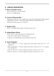
... Plug and Play Plug and play allows the serial communication of host PC and peripherals offering minimal configurations to U4 (24LC21A). Power Regulator (1)The U12(APL117) is 1A linear regulator that transfer input voltage from 5V to 3.3V supports U5. (2)The U13(AIC1084) is 5A linear regulator that transfer voltage from 5V to 3.3V supports U17 and Panel...
... Plug and Play Plug and play allows the serial communication of host PC and peripherals offering minimal configurations to U4 (24LC21A). Power Regulator (1)The U12(APL117) is 1A linear regulator that transfer input voltage from 5V to 3.3V supports U5. (2)The U13(AIC1084) is 5A linear regulator that transfer voltage from 5V to 3.3V supports U17 and Panel...
AL511 Service Guide
Page 18
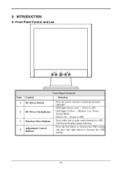
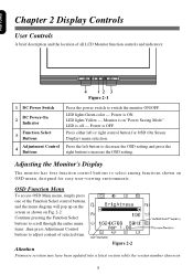
INTRODUCTION A. LED lights Green color --- LED is in "Power Saving Mode". Press either left button to decrease the OSD setting and press the right button to switch the monitor ON/OFF. 9. Monitor is off --- LED lights Yellow --- Front Panel Control and Led Item 1 2 3 4 Front Panel Controls Control Function DC Power Switch DC Power-On Indicator Function Select Buttons Adjustment Control Buttons Press the power switch to increase the OSD setting. 18 Power is ON. Press the left or right control button for OSD (On Screen Display) menu selection. Power is OFF.
INTRODUCTION A. LED lights Green color --- LED is in "Power Saving Mode". Press either left button to decrease the OSD setting and press the right button to switch the monitor ON/OFF. 9. Monitor is off --- LED lights Yellow --- Front Panel Control and Led Item 1 2 3 4 Front Panel Controls Control Function DC Power Switch DC Power-On Indicator Function Select Buttons Adjustment Control Buttons Press the power switch to increase the OSD setting. 18 Power is ON. Press the left or right control button for OSD (On Screen Display) menu selection. Power is OFF.
AL511 User Guide
Page 1
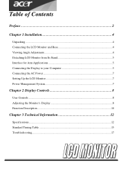
Table of Contents Preface ...2 Chapter 1 Installation 4 Unpacking ...4 Connecting the LCD Monitor and Base 4 Viewing Angle Adjustment ...4 Detaching LCD Monitor from Its Stand 5 Interface for Arm Applications 5 Connecting the Display to your Computer 5 Connecting the AC Power...7 Setting Up the LCD Monitor...7 Power Management System...7 Chapter 2 Display Controls 8 User Controls ...8 Adjusting the Monitor's Display 8 Function Description...10 Chapter 3 Technical Information 12 Specifications...12 Standard Timing Table ...15 Troubleshooting...17
Table of Contents Preface ...2 Chapter 1 Installation 4 Unpacking ...4 Connecting the LCD Monitor and Base 4 Viewing Angle Adjustment ...4 Detaching LCD Monitor from Its Stand 5 Interface for Arm Applications 5 Connecting the Display to your Computer 5 Connecting the AC Power...7 Setting Up the LCD Monitor...7 Power Management System...7 Chapter 2 Display Controls 8 User Controls ...8 Adjusting the Monitor's Display 8 Function Description...10 Chapter 3 Technical Information 12 Specifications...12 Standard Timing Table ...15 Troubleshooting...17

AL511 User Guide
Page 2
... provide reasonable protection against harmful interference in setting up and using the LCD Monitor. However, there is no guarantee is subject to assist users in a residential installation. This equipment generates, uses, and can be determined by turning the equipment off and on, the user is required in this manual may cause harmful interference to Part 15 of the FCC Rules. Canadian...
... provide reasonable protection against harmful interference in setting up and using the LCD Monitor. However, there is no guarantee is subject to assist users in a residential installation. This equipment generates, uses, and can be determined by turning the equipment off and on, the user is required in this manual may cause harmful interference to Part 15 of the FCC Rules. Canadian...
AL511 User Guide
Page 3
... cleaning solution onto a rag. -- Servicing of any of the following instructions carefully. A certified line is frayed or damaged. * Liquid spilled into LCD Monitor or the monitor has been exposed to the LCD screen. Power off LCD Monitor and unplug the AC Cord. -- For a nominal current up to a power outlet. This manual should be used. 8. Do not place the LCD Monitor near a window. Do not remove the cover or attempt to service...
... cleaning solution onto a rag. -- Servicing of any of the following instructions carefully. A certified line is frayed or damaged. * Liquid spilled into LCD Monitor or the monitor has been exposed to the LCD screen. Power off LCD Monitor and unplug the AC Cord. -- For a nominal current up to a power outlet. This manual should be used. 8. Do not place the LCD Monitor near a window. Do not remove the cover or attempt to service...
AL511 User Guide
Page 4
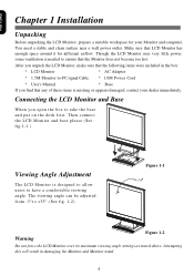
... unpack the LCD Monitor, make sure that the Monitor does not become too hot. Then connect the LCD Monitor and base please.(See fig.1-1 ) Viewing Angle Adjustment The LCD Monitor is needed to take the base and put on the desk first. You need a stable and clean surface near a wall power outlet. Attempting this will result in the box: * LCD Monitor * AC Adapter * 1.5M Monitor-to-PC signal Cable * 1.8M Power Cord * User's Manual * Base If you open the box...
... unpack the LCD Monitor, make sure that the Monitor does not become too hot. Then connect the LCD Monitor and base please.(See fig.1-1 ) Viewing Angle Adjustment The LCD Monitor is needed to take the base and put on the desk first. You need a stable and clean surface near a wall power outlet. Attempting this will result in the box: * LCD Monitor * AC Adapter * 1.5M Monitor-to-PC signal Cable * 1.8M Power Cord * User's Manual * Base If you open the box...

AL511 User Guide
Page 5
.... 4. These specifications meet the VESA Flat Panel Monitor Physical Mounting Interface Standard (paragraphs 2.1 and 2.1.3, version 1, dated 13 November 1997). Power off -the-shelf video cable in the LCD Monitor package. This device will not be connected to comply with FCC regulations when a non-ferrite-core video cable is included in order to an off your computer. 2. The rear of the signal cable to the LCD Monitor's VGA port. (See Fig...
.... 4. These specifications meet the VESA Flat Panel Monitor Physical Mounting Interface Standard (paragraphs 2.1 and 2.1.3, version 1, dated 13 November 1997). Power off -the-shelf video cable in the LCD Monitor package. This device will not be connected to comply with FCC regulations when a non-ferrite-core video cable is included in order to an off your computer. 2. The rear of the signal cable to the LCD Monitor's VGA port. (See Fig...
AL511 User Guide
Page 7
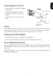
... LCD Monitor complies with the VESA DPMS (version 1.0) Power Management guidelines. Turn on the LCD Monitor's power switch, located on the bezel of sudden voltage variations from reaching the LCD Monitor. signal. Connect the power cord to prevent the effects of the monitor. When the LCD Monitor is connected to the LCD Monitor. 2. Sudden power surges may damage your monitor. Make sure the AC Adapter is in power saving mode, the monitor screen will be blank and the power LED indicator will light...
... LCD Monitor complies with the VESA DPMS (version 1.0) Power Management guidelines. Turn on the LCD Monitor's power switch, located on the bezel of sudden voltage variations from reaching the LCD Monitor. signal. Connect the power cord to prevent the effects of the monitor. When the LCD Monitor is connected to the LCD Monitor. 2. Sudden power surges may damage your monitor. Make sure the AC Adapter is in power saving mode, the monitor screen will be blank and the power LED indicator will light...
AL511 User Guide
Page 8
... OSD (On Screen Display) menu selection. LED lights Yellow --- Power is OFF. Press the left or right control button for easy user-viewing environments. LED lights Green color --- LED is in "Power Saving Mode". Monitor is off --- Figure 2-2 Attention Firmware revision may have been updated into a latest version while the version number shown on Fig. 2-2: Continue pressing the Function Select buttons to scroll through the entire menu items ,then press Adjustment Control buttons to adjust content of all LCD Monitor function controls...
... OSD (On Screen Display) menu selection. LED lights Yellow --- Power is OFF. Press the left or right control button for easy user-viewing environments. LED lights Green color --- LED is in "Power Saving Mode". Monitor is off --- Figure 2-2 Attention Firmware revision may have been updated into a latest version while the version number shown on Fig. 2-2: Continue pressing the Function Select buttons to scroll through the entire menu items ,then press Adjustment Control buttons to adjust content of all LCD Monitor function controls...
AL511 User Guide
Page 10
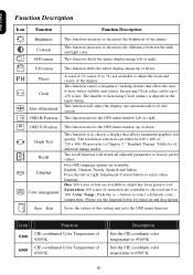
... available: English, German, French, Spanish and Italian. The number of the image. The resolution selection can be 640 x 400 or 720 x 400. Color Temp.: Push the (+ -) button to factory preset values. This function shifts the entire display image left or right. OSD V-Position Graph Text Recall Language Color management This function moves the OSD menu window up or down . Five OSD language options are available to adjust the focus...
... available: English, German, French, Spanish and Italian. The number of the image. The resolution selection can be 640 x 400 or 720 x 400. Color Temp.: Push the (+ -) button to factory preset values. This function shifts the entire display image left or right. OSD V-Position Graph Text Recall Language Color management This function moves the OSD menu window up or down . Five OSD language options are available to adjust the focus...
AL511 User Guide
Page 12
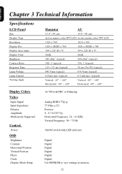
Chapter 3 Technical Information Specifications LCD Panel Size Display Type Resolution Display Dot Display Area (mm) Display Color Brightness Contrast Ratio Response Time Lamp Voltage Lamp Current Viewing Angle Display Colors Video Input Signal Input Impedance Polarity Amplitude Multi-mode Supported Control Power OSD Brightness Contrast Horizontal Position Vertical Position Phase Clock Display Mode Setup Hannstar AU 15.0" (38 cm) 15.0" (38 cm) Active matrix color TFT LCD Active matrix color TFT LCD 1024 x 768 1024 x 768 1024 x (RGB) x 768 1024 x (RGB) x 768 304 x 228 (H x V) 304 x ...
Chapter 3 Technical Information Specifications LCD Panel Size Display Type Resolution Display Dot Display Area (mm) Display Color Brightness Contrast Ratio Response Time Lamp Voltage Lamp Current Viewing Angle Display Colors Video Input Signal Input Impedance Polarity Amplitude Multi-mode Supported Control Power OSD Brightness Contrast Horizontal Position Vertical Position Phase Clock Display Mode Setup Hannstar AU 15.0" (38 cm) 15.0" (38 cm) Active matrix color TFT LCD Active matrix color TFT LCD 1024 x 768 1024 x 768 1024 x (RGB) x 768 1024 x (RGB) x 768 304 x 228 (H x V) 304 x ...
AL511 User Guide
Page 14
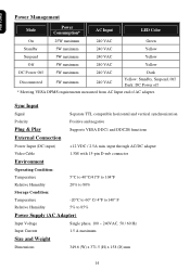
... 5% to 85% Power Supply (AC Adapter) Input Voltage Single phase, 100 ~ 240VAC, 50 / 60 Hz Input Current 1.5 A maximum Size and Weight Dimensions 349.6 (W) x 371.5 (H) x 158 (D) mm 14 Sync Input Signal Separate TTL compatible horizontal and vertical synchronization Polarity Positive and negative Plug & Play Supports VESA DDC1 and DDC2B functions External Connection Power Input (DC input) +12 VDC / 2.5A min. Power Management Mode Power Consumption* AC Input LED Color On 25W maximum 240 VAC Green Standby 5W maximum...
... 5% to 85% Power Supply (AC Adapter) Input Voltage Single phase, 100 ~ 240VAC, 50 / 60 Hz Input Current 1.5 A maximum Size and Weight Dimensions 349.6 (W) x 371.5 (H) x 158 (D) mm 14 Sync Input Signal Separate TTL compatible horizontal and vertical synchronization Polarity Positive and negative Plug & Play Supports VESA DDC1 and DDC2B functions External Connection Power Input (DC input) +12 VDC / 2.5A min. Power Management Mode Power Consumption* AC Input LED Color On 25W maximum 240 VAC Green Standby 5W maximum...
AL511 User Guide
Page 15
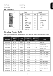
ENGLISH Net Weight Gross Weight Pin Assignment 6 3.2 ± 0.3 kg 4.7 ± 0.3 kg Signal Signal PIN Description PIN Description 1 Red 9 +5V 1 11 2 Green 10 NC 3 Blue 11 Digital GND 4 Digital GND 12 SDA 5 15 5 Digital GND 13 H. Sync. 6 Red Rtn 14 V. Freq. (Hz) Pixel Freq. (MHz) H/V Sync. VGA-400-GRAPH NEC PC9821 640 x 480 31.469 59.940 25.175 -/- XGA 15 Freq. (KHz) V. NEC PC9801 640...
ENGLISH Net Weight Gross Weight Pin Assignment 6 3.2 ± 0.3 kg 4.7 ± 0.3 kg Signal Signal PIN Description PIN Description 1 Red 9 +5V 1 11 2 Green 10 NC 3 Blue 11 Digital GND 4 Digital GND 12 SDA 5 15 5 Digital GND 13 H. Sync. 6 Red Rtn 14 V. Freq. (Hz) Pixel Freq. (MHz) H/V Sync. VGA-400-GRAPH NEC PC9821 640 x 480 31.469 59.940 25.175 -/- XGA 15 Freq. (KHz) V. NEC PC9801 640...
AL511 User Guide
Page 17
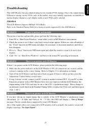
... there's any black vertical stripes appear. Check the screen to "Shut Down Windows" status while you have chosen an output timing that is no picture, press the Adjustment Control button several times. 3. Turn off the LCD Monitor and then turn it does not function with the LCD Monitor, the output timing of modes supported by increment or decrement numbers) until those bars disappear. 3. Please change to another external CRT. Due...
... there's any black vertical stripes appear. Check the screen to "Shut Down Windows" status while you have chosen an output timing that is no picture, press the Adjustment Control button several times. 3. Turn off the LCD Monitor and then turn it does not function with the LCD Monitor, the output timing of modes supported by increment or decrement numbers) until those bars disappear. 3. Please change to another external CRT. Due...


