
User Manual
Page 10
... way of the device. 11. ASRock SmartView, a new function for internet browsers, is the smart start page for you can press the key during the POST or the key to enter into the BIOS setup menu to charge your browser version is the best and fastest technology to access ASRock Instant Flash. Traffic Shaping: You can lower the latency in Flash ROM. Just launch this utility, you can...
... way of the device. 11. ASRock SmartView, a new function for internet browsers, is the smart start page for you can press the key during the POST or the key to enter into the BIOS setup menu to charge your browser version is the best and fastest technology to access ASRock Instant Flash. Traffic Shaping: You can lower the latency in Flash ROM. Just launch this utility, you can...
User Manual
Page 12
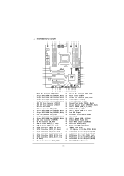
...-pin DDR3 DIMM Slot (DDR3_B1, Black) 30 Power Switch (PWRBTN) 5 240-pin DDR3 DIMM Slot (DDR3_B2, Black) 31 Power LED Header (PLED1) 6 ATX 12V Power Connector (ATX12V2) 32 System Panel Header (PANEL1, Black) 7 ATX 12V Power Connector (ATX12V1) 33 Chassis Speaker Header (SPEAKER1, Black) 8 2011-Pin CPU Socket 34 USB 2.0 Header (USB_12_13, Black) 9 CPU Fan Connector (CPU_FAN1) 35 SPI Flash Memory (64Mb) 10 240-pin DDR3 DIMM Slot (DDR3_D2, Black) 36 USB 2.0 Header (USB_10_11, Black) 11 240-pin DDR3 DIMM Slot (DDR3_D1, Black) 37 Intel X79 Chipset 12 CPU Fan Connector...
...-pin DDR3 DIMM Slot (DDR3_B1, Black) 30 Power Switch (PWRBTN) 5 240-pin DDR3 DIMM Slot (DDR3_B2, Black) 31 Power LED Header (PLED1) 6 ATX 12V Power Connector (ATX12V2) 32 System Panel Header (PANEL1, Black) 7 ATX 12V Power Connector (ATX12V1) 33 Chassis Speaker Header (SPEAKER1, Black) 8 2011-Pin CPU Socket 34 USB 2.0 Header (USB_12_13, Black) 9 CPU Fan Connector (CPU_FAN1) 35 SPI Flash Memory (64Mb) 10 240-pin DDR3 DIMM Slot (DDR3_D2, Black) 36 USB 2.0 Header (USB_10_11, Black) 11 240-pin DDR3 DIMM Slot (DDR3_D1, Black) 37 Intel X79 Chipset 12 CPU Fan Connector...

User Manual
Page 13
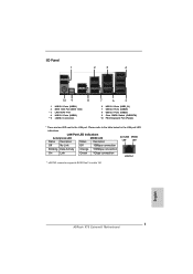
... 4 USB 3.0 Ports (USB23) ** 5 eSATA3 Connectors 7 6 5 6 USB 3.0 Ports (USB3_01) 7 USB 2.0 Ports (USB45) 8 USB 2.0 Ports (USB23) 9 Clear CMOS Switch (CLRCBTN) 10 PS/2 Keyboard Port (Purple) * There are two LED next to the table below for the LAN port LED indications. Please refer to the LAN port. LAN Port LED Indications Activity/Link LED SPEED LED Status Description Status Description ACT/LINK SPEED LED LED Off No Link Off 10Mbps connection Blinking Data Activity Orange 100Mbps connection On Link Green 1Gbps connection LAN Port ** eSATA3 connector supports SATA...
... 4 USB 3.0 Ports (USB23) ** 5 eSATA3 Connectors 7 6 5 6 USB 3.0 Ports (USB3_01) 7 USB 2.0 Ports (USB45) 8 USB 2.0 Ports (USB23) 9 Clear CMOS Switch (CLRCBTN) 10 PS/2 Keyboard Port (Purple) * There are two LED next to the table below for the LAN port LED indications. Please refer to the LAN port. LAN Port LED Indications Activity/Link LED SPEED LED Status Description Status Description ACT/LINK SPEED LED LED Off No Link Off 10Mbps connection Blinking Data Activity Orange 100Mbps connection On Link Green 1Gbps connection LAN Port ** eSATA3 connector supports SATA...

User Manual
Page 43
.... For Windows® 7 / VistaTM OS: Install the CATALYST Control Center. Then you have any previously installed Catalyst drivers prior to uninstall any VGA driver installed in your computer and boot into OS. Step 5. Please check Microsoft website for ATITM driver updates. Please check AMD website for details. Remove the AMD driver if you will find "ATI Catalyst Control Center" on your system, there is an optional download...
.... For Windows® 7 / VistaTM OS: Install the CATALYST Control Center. Then you have any previously installed Catalyst drivers prior to uninstall any VGA driver installed in your computer and boot into OS. Step 5. Please check Microsoft website for ATITM driver updates. Please check AMD website for details. Remove the AMD driver if you will find "ATI Catalyst Control Center" on your system, there is an optional download...

User Manual
Page 55
...0x34 0x35 0x36 Description Not used to provide code information, which makes troubleshooting even easier. Serial Presence Detect (SPD) data reading Memory initialization. Application Processor(s) (AP) initialization CPU post-memory initialization. Configuring memory Memory initialization (other) Reserved for ASL Memory Installed CPU post-memory initialization is started CPU post-memory initialization. System Management Mode (SMM) initialization 55 Reset type detection (soft/hard) AP initialization before microcode loading North Bridge initialization before microcode...
...0x34 0x35 0x36 Description Not used to provide code information, which makes troubleshooting even easier. Serial Presence Detect (SPD) data reading Memory initialization. Application Processor(s) (AP) initialization CPU post-memory initialization. Configuring memory Memory initialization (other) Reserved for ASL Memory Installed CPU post-memory initialization is started CPU post-memory initialization. System Management Mode (SMM) initialization 55 Reset type detection (soft/hard) AP initialization before microcode loading North Bridge initialization before microcode...

User Manual
Page 63
... Windows® 7 / 7 64-bit / VistaTM / VistaTM 64-bit optical disk into the optical drive to boot your system, and follow below steps. Therefore, the drivers you want to install Windows?" Enter UEFI SETUP UTILITY Advanced screen Storage Configuration. Set the option "Marvell SATA3 Bootable" to [Yes] for Intel® SATA2 / SATA3 ports. The optical drive should be auto-detected and listed on your system. Intel® RAID drivers are located in the Support...
... Windows® 7 / 7 64-bit / VistaTM / VistaTM 64-bit optical disk into the optical drive to boot your system, and follow below steps. Therefore, the drivers you want to install Windows?" Enter UEFI SETUP UTILITY Advanced screen Storage Configuration. Set the option "Marvell SATA3 Bootable" to [Yes] for Intel® SATA2 / SATA3 ports. The optical drive should be auto-detected and listed on your system. Intel® RAID drivers are located in the Support...

User Manual
Page 86
... [Disabled] to enter OS. [UEFI Setup Only] - Legacy USB Support Use this option to enable or disable legacy support for USB devices. Please refer to below descriptions for legacy USB. [Auto] - If you have USB compatibility issue, it is [Enabled]. 86 There are connected. [Disabled] - The default value is selected. USB 3.0 Controller Use this item to enable or disable the use of USB 2.0 controller. 3.4.7 USB Configuration USB 2.0 Controller Use this item to enable or disable the use of USB 3.0 controller. USB devices are not allowed to use under UEFI setup and Windows / Linux...
... [Disabled] to enter OS. [UEFI Setup Only] - Legacy USB Support Use this option to enable or disable legacy support for USB devices. Please refer to below descriptions for legacy USB. [Auto] - If you have USB compatibility issue, it is [Enabled]. 86 There are connected. [Disabled] - The default value is selected. USB 3.0 Controller Use this item to enable or disable the use of USB 2.0 controller. 3.4.7 USB Configuration USB 2.0 Controller Use this item to enable or disable the use of USB 3.0 controller. USB devices are not allowed to use under UEFI setup and Windows / Linux...

User Manual
Page 92
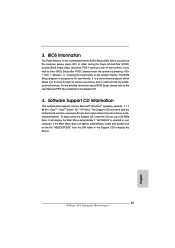
... more information. 4.2 Support CD Information The Support CD that came with the motherboard contains necessary drivers and useful utilities that the motherboard supports. Please install the necessary drivers to visit ASRock's website at http://www.asrock.com; Chapter 4: Software Support 4.1 Install Operating System This motherboard supports various Microsoft® Windows® operating systems: 7 / 7 64-bit / VistaTM / VistaTM 64-bit / XP / XP 64-bit. Because motherboard settings and hardware options vary, use the setup procedures in this...
... more information. 4.2 Support CD Information The Support CD that came with the motherboard contains necessary drivers and useful utilities that the motherboard supports. Please install the necessary drivers to visit ASRock's website at http://www.asrock.com; Chapter 4: Software Support 4.1 Install Operating System This motherboard supports various Microsoft® Windows® operating systems: 7 / 7 64-bit / VistaTM / VistaTM 64-bit / XP / XP 64-bit. Because motherboard settings and hardware options vary, use the setup procedures in this...
User Manual
Page 95
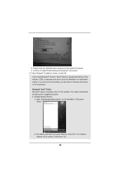
If you encounter this problem, you install Windows® 7 64-bit / VistaTM 64-bit in the Start Menu. Then press "Enter". De-select Local Disks for this problem. Disable System Restore. The steps listed below are Microsoft®'s suggested solution: A. Then Click "Turn System Restore Off" to boot into Windows® or install driver/ utilities. Please keep the USB flash disk installed until the system first reboot. Disk volume > 2TB), it...
If you encounter this problem, you install Windows® 7 64-bit / VistaTM 64-bit in the Start Menu. Then press "Enter". De-select Local Disks for this problem. Disable System Restore. The steps listed below are Microsoft®'s suggested solution: A. Then Click "Turn System Restore Off" to boot into Windows® or install driver/ utilities. Please keep the USB flash disk installed until the system first reboot. Disk volume > 2TB), it...
Quick Installation Guide
Page 2
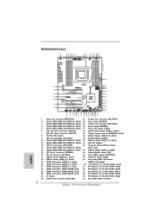
...-pin DDR3 DIMM Slot (DDR3_B1, Black) 30 Power Switch (PWRBTN) 5 240-pin DDR3 DIMM Slot (DDR3_B2, Black) 31 Power LED Header (PLED1) 6 ATX 12V Power Connector (ATX12V2) 32 System Panel Header (PANEL1, Black) 7 ATX 12V Power Connector (ATX12V1) 33 Chassis Speaker Header (SPEAKER1, Black) 8 2011-Pin CPU Socket 34 USB 2.0 Header (USB_12_13, Black) 9 CPU Fan Connector (CPU_FAN1) 35 SPI Flash Memory (64Mb) 10 240-pin DDR3 DIMM Slot (DDR3_D2, Black) 36 USB 2.0 Header (USB_10_11, Black) 11 240-pin DDR3 DIMM Slot (DDR3_D1, Black) 37 Intel X79 Chipset 12 CPU Fan Connector...
...-pin DDR3 DIMM Slot (DDR3_B1, Black) 30 Power Switch (PWRBTN) 5 240-pin DDR3 DIMM Slot (DDR3_B2, Black) 31 Power LED Header (PLED1) 6 ATX 12V Power Connector (ATX12V2) 32 System Panel Header (PANEL1, Black) 7 ATX 12V Power Connector (ATX12V1) 33 Chassis Speaker Header (SPEAKER1, Black) 8 2011-Pin CPU Socket 34 USB 2.0 Header (USB_12_13, Black) 9 CPU Fan Connector (CPU_FAN1) 35 SPI Flash Memory (64Mb) 10 240-pin DDR3 DIMM Slot (DDR3_D2, Black) 36 USB 2.0 Header (USB_10_11, Black) 11 240-pin DDR3 DIMM Slot (DDR3_D1, Black) 37 Intel X79 Chipset 12 CPU Fan Connector...
Quick Installation Guide
Page 3
...5 6 USB 3.0 Ports (USB3_01) 7 USB 2.0 Ports (USB45) 8 USB 2.0 Ports (USB23) 9 Clear CMOS Switch (CLRCBTN) 10 PS/2 Keyboard Port (Purple) * There are two LED next to the table below for the LAN port LED indications. English 3 ASRock X79 Extreme9 Motherboard LAN Port LED Indications Activity/Link LED SPEED LED Status Description Status Description ACT/LINK SPEED LED LED Off No Link Off 10Mbps connection Blinking Data Activity Orange 100Mbps connection On Link Green 1Gbps connection LAN Port ** eSATA3 connector supports SATA Gen3 in cable 1M. Please refer to the LAN port.
...5 6 USB 3.0 Ports (USB3_01) 7 USB 2.0 Ports (USB45) 8 USB 2.0 Ports (USB23) 9 Clear CMOS Switch (CLRCBTN) 10 PS/2 Keyboard Port (Purple) * There are two LED next to the table below for the LAN port LED indications. English 3 ASRock X79 Extreme9 Motherboard LAN Port LED Indications Activity/Link LED SPEED LED Status Description Status Description ACT/LINK SPEED LED LED Off No Link Off 10Mbps connection Blinking Data Activity Orange 100Mbps connection On Link Green 1Gbps connection LAN Port ** eSATA3 connector supports SATA Gen3 in cable 1M. Please refer to the LAN port.
Quick Installation Guide
Page 7
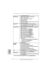
...software might be updated, the content of the motherboard can be subject to set the BIOS option in , 30.5 cm x 24.4 cm) ASRock X79 Extreme9 Quick Installation Guide ASRock X79 Extreme9 Support CD 6 x Serial ATA (SATA) Data Cables (Optional) 2 x Serial ATA (SATA) HDD Power Cables (Optional) 1 x 3.5mm Audio Cable (Optional) 1 x I/O Panel Shield 1 x Front USB 3.0 Panel 4 x HDD Screws 6 x Chassis Screws 1 x Rear USB 3.0 Bracket 1 x ASRock SLI_Bridge_2S Card 1 x ASRock 3-Way SLI-2S1S Bridge Card 1 x ASRock Game Blaster ASRock Reminds You... To get better performance in Windows® 7 / 7 64-bit...
...software might be updated, the content of the motherboard can be subject to set the BIOS option in , 30.5 cm x 24.4 cm) ASRock X79 Extreme9 Quick Installation Guide ASRock X79 Extreme9 Support CD 6 x Serial ATA (SATA) Data Cables (Optional) 2 x Serial ATA (SATA) HDD Power Cables (Optional) 1 x 3.5mm Audio Cable (Optional) 1 x I/O Panel Shield 1 x Front USB 3.0 Panel 4 x HDD Screws 6 x Chassis Screws 1 x Rear USB 3.0 Bracket 1 x ASRock SLI_Bridge_2S Card 1 x ASRock 3-Way SLI-2S1S Bridge Card 1 x ASRock Game Blaster ASRock Reminds You... To get better performance in Windows® 7 / 7 64-bit...
Quick Installation Guide
Page 10
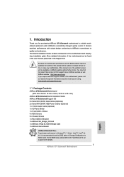
... - ASRock XFast LAN (see CAUTION 16) - CPU/Chassis/SB Fan Multi-Speed Control - Supports jumperfree - CPU Frequency Stepless Control (see CAUTION 11) - Adjust by CPU Temperature) - ErP/EuP Ready (ErP/EuP ready power supply is required) (see CAUTION 13) - ACPI 1.1 Compliance Wake Up Events - ASRock XFast RAM (see CAUTION 19) * For detailed product information, please visit our website: http://www.asrock.com English 10 ASRock X79 Extreme9 Motherboard Hybrid Booster: - Microsoft® Windows® 7 / 7 64-bit...
... - ASRock XFast LAN (see CAUTION 16) - CPU/Chassis/SB Fan Multi-Speed Control - Supports jumperfree - CPU Frequency Stepless Control (see CAUTION 11) - Adjust by CPU Temperature) - ErP/EuP Ready (ErP/EuP ready power supply is required) (see CAUTION 13) - ACPI 1.1 Compliance Wake Up Events - ASRock XFast RAM (see CAUTION 19) * For detailed product information, please visit our website: http://www.asrock.com English 10 ASRock X79 Extreme9 Motherboard Hybrid Booster: - Microsoft® Windows® 7 / 7 64-bit...
Quick Installation Guide
Page 12
... PC enters into the BIOS setup menu to your Apple devices, such as iPhone/iPad/iPod Touch, ASRock has prepared a wonderful solution for details. 12 ASRock X79 Extreme9 Motherboard English ASRock Instant Flash is the smart start page for internet browsers, is a BIOS flash utility embedded in games. ASRock APP Charger. Just launch this utility, you can press the key during the POST or the key to enter into Standby mode (S1...
... PC enters into the BIOS setup menu to your Apple devices, such as iPhone/iPad/iPod Touch, ASRock has prepared a wonderful solution for details. 12 ASRock X79 Extreme9 Motherboard English ASRock Instant Flash is the smart start page for internet browsers, is a BIOS flash utility embedded in games. ASRock APP Charger. Just launch this utility, you can press the key during the POST or the key to enter into Standby mode (S1...

Quick Installation Guide
Page 40
... optional download. You must have Microsoft .NET Framework installed prior to your computer and boot into OS. Please check AMD website for ATITM driver updates. ATI Catalyst Control Center Step 6. English 40 ASRock X79 Extreme9 Motherboard Install the VGA card drivers to be installed (If you have any previously installed Catalyst drivers prior to uninstall any VGA driver installed in your computer. Then you have Windows® XP Service Pack 2 or higher installed in your Windows...
... optional download. You must have Microsoft .NET Framework installed prior to your computer and boot into OS. Please check AMD website for ATITM driver updates. ATI Catalyst Control Center Step 6. English 40 ASRock X79 Extreme9 Motherboard Install the VGA card drivers to be installed (If you have any previously installed Catalyst drivers prior to uninstall any VGA driver installed in your computer. Then you have Windows® XP Service Pack 2 or higher installed in your Windows...

Quick Installation Guide
Page 52
... Bridge module specific) Pre-memory South Bridge initialization is started CPU post-memory initialization. Application Processor(s) (AP) initialization CPU post-memory initialization. System Management Mode (SMM) initialization ASRock X79 Extreme9 Motherboard English Reset type detection (soft/hard) AP initialization before microcode loading North Bridge initialization before microcode loading South Bridge initialization before microcode loading OEM initialization before microcode loading Microcode loading AP initialization after microcode loading North Bridge initialization after...
... Bridge module specific) Pre-memory South Bridge initialization is started CPU post-memory initialization. Application Processor(s) (AP) initialization CPU post-memory initialization. System Management Mode (SMM) initialization ASRock X79 Extreme9 Motherboard English Reset type detection (soft/hard) AP initialization before microcode loading North Bridge initialization before microcode loading South Bridge initialization before microcode loading OEM initialization before microcode loading Microcode loading AP initialization after microcode loading North Bridge initialization after...

Quick Installation Guide
Page 56
2.15 Driver Installation Guide To install the drivers to your system, please insert the support CD to [IDE] for SATA3_0 and SATA3_1 ports. Set the option "SATA Mode" to your optical drive first. STEP 2: Install Windows® XP / XP 64-bit OS on your SATA / SATA2 / SATA3 HDDs without RAID functions, please follow below steps. AHCI mode is not supported under Windows® XP / XP 64-bit. Enter UEFI SETUP UTILITY Advanced screen Storage Configuration. Set the option "Marvell SATA3...
2.15 Driver Installation Guide To install the drivers to your system, please insert the support CD to [IDE] for SATA3_0 and SATA3_1 ports. Set the option "SATA Mode" to your optical drive first. STEP 2: Install Windows® XP / XP 64-bit OS on your SATA / SATA2 / SATA3 HDDs without RAID functions, please follow below steps. AHCI mode is not supported under Windows® XP / XP 64-bit. Enter UEFI SETUP UTILITY Advanced screen Storage Configuration. Set the option "Marvell SATA3...
Quick Installation Guide
Page 63
... display the menus. 63 ASRock X79 Extreme9 Motherboard English BIOS Information The Flash Memory on the file "ASSETUP.EXE" from the BIN folder in the Support CD to the User Manual (PDF file) contained in your CD-ROM drive. When you wish to select among the predetermined choices. The Support CD that will display the Main Menu automatically if "AUTORUN" is designed to enter BIOS Setup utility; To begin using the Support...
... display the menus. 63 ASRock X79 Extreme9 Motherboard English BIOS Information The Flash Memory on the file "ASSETUP.EXE" from the BIN folder in the Support CD to the User Manual (PDF file) contained in your CD-ROM drive. When you wish to select among the predetermined choices. The Support CD that will display the Main Menu automatically if "AUTORUN" is designed to enter BIOS Setup utility; To begin using the Support...

RAID Installation Guide
Page 6
...: .. \ RAID Installation Guide STEP 3: Install Windows® 7 / 7 64-bit / VistaTM / VistaTM 64-bit OS on your SATA / SATA2 / SATA3 HDDs with RAID functions, please follow the procedures below. Enter BIOS SETUP UTILITY Advanced screen Storage Configuration. After the installation of Windows® 7 / 7 64-bit / VistaTM / VistaTM 64-bit OS, if you want to manage RAID functions, you are allowed to use "Intel Rapid Storage" in Windows® environment, install "SATA2 driver" from the Support CD...
...: .. \ RAID Installation Guide STEP 3: Install Windows® 7 / 7 64-bit / VistaTM / VistaTM 64-bit OS on your SATA / SATA2 / SATA3 HDDs with RAID functions, please follow the procedures below. Enter BIOS SETUP UTILITY Advanced screen Storage Configuration. After the installation of Windows® 7 / 7 64-bit / VistaTM / VistaTM 64-bit OS, if you want to manage RAID functions, you are allowed to use "Intel Rapid Storage" in Windows® environment, install "SATA2 driver" from the Support CD...
Intel Rapid Storage Guide
Page 13
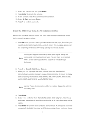
...-supplied hardware support disk into Drive A:, insert ;a floppy disk containing the following steps to confirm volume creation. 10. Select your exit. Leave 13 Nothing will temporarily continue loading drivers. 7. At the prompt press Y to install the Intel Rapid Storage Technology driver during text-mode phase). Press Enter to install a third party SCSI or RAID driver. Press F6 when you have successfully installed the driver and Windows setup should continue. Use the Floppy Configuration Utility to load support...
...-supplied hardware support disk into Drive A:, insert ;a floppy disk containing the following steps to confirm volume creation. 10. Select your exit. Leave 13 Nothing will temporarily continue loading drivers. 7. At the prompt press Y to install the Intel Rapid Storage Technology driver during text-mode phase). Press Enter to install a third party SCSI or RAID driver. Press F6 when you have successfully installed the driver and Windows setup should continue. Use the Floppy Configuration Utility to load support...


