
User Manual
Page 3
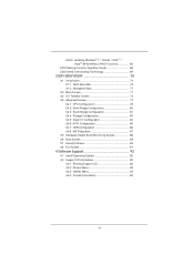
... Contents 5 1.2 Specifications 6 1.3 Motherboard Layout 12 1.4 I/O Panel 13 1.5 ASRock Game Blaster 14 2 Installation 17 2.1 Screw Holes 17 2.2 Pre-installation Precautions 17 2.3 CPU Installation 18 2.4 Installation of Heatsink and CPU fan 20 2.5 Installation of Memory Modules (DIMM 21 2.6 Expansion Slots (PCI Express Slots 23 2.7 ASRock Game Blaster Installation Guide 25 2.8 SLITM, 3-Way SLITM and...
... Contents 5 1.2 Specifications 6 1.3 Motherboard Layout 12 1.4 I/O Panel 13 1.5 ASRock Game Blaster 14 2 Installation 17 2.1 Screw Holes 17 2.2 Pre-installation Precautions 17 2.3 CPU Installation 18 2.4 Installation of Heatsink and CPU fan 20 2.5 Installation of Memory Modules (DIMM 21 2.6 Expansion Slots (PCI Express Slots 23 2.7 ASRock Game Blaster Installation Guide 25 2.8 SLITM, 3-Way SLITM and...
User Manual
Page 4
... Technology 69 3 UEFI SETUP UTILITY 70 3.1 Introduction 70 3.1.1 UEFI Menu Bar 70 3.1.2 Navigation Keys 71 3.2 Main Screen 71 3.3 OC Tweaker Screen 72 3.4 Advanced Screen 77 3.4.1 CPU Configuration 78 3.4.2 North Bridge Configuration 80 3.4.3 South Bridge Configuration 81 3.4.4 Storage Configuration 83 3.4.5 Super IO Confi...
... Technology 69 3 UEFI SETUP UTILITY 70 3.1 Introduction 70 3.1.1 UEFI Menu Bar 70 3.1.2 Navigation Keys 71 3.2 Main Screen 71 3.3 OC Tweaker Screen 72 3.4 Advanced Screen 77 3.4.1 CPU Configuration 78 3.4.2 North Bridge Configuration 80 3.4.3 South Bridge Configuration 81 3.4.4 Storage Configuration 83 3.4.5 Super IO Confi...
User Manual
Page 5
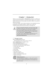
... quality and endurance. For the BIOS setup, please refer to set the BIOS option in , 30.5 cm x 24.4 cm) ASRock X79 Extreme9 Quick Installation Guide ASRock X79 Extreme9 Support CD 6 x Serial ATA (SATA) Data Cables (Optional) 2 x Serial ATA (SATA) HDD Power Cables (Optional) 1... 1 x I/O Panel Shield 1 x Front USB 3.0 Panel 4 x HDD Screws 6 x Chassis Screws 1 x Rear USB 3.0 Bracket 1 x ASRock SLI_Bridge_2S Card 1 x ASRock 3-Way SLI-2S1S Bridge Card 1 x ASRock Game Blaster ASRock Reminds You... You may find the latest VGA cards and CPU support lists on ASRock website without notice.
... quality and endurance. For the BIOS setup, please refer to set the BIOS option in , 30.5 cm x 24.4 cm) ASRock X79 Extreme9 Quick Installation Guide ASRock X79 Extreme9 Support CD 6 x Serial ATA (SATA) Data Cables (Optional) 2 x Serial ATA (SATA) HDD Power Cables (Optional) 1... 1 x I/O Panel Shield 1 x Front USB 3.0 Panel 4 x HDD Screws 6 x Chassis Screws 1 x Rear USB 3.0 Bracket 1 x ASRock SLI_Bridge_2S Card 1 x ASRock 3-Way SLI-2S1S Bridge Card 1 x ASRock Game Blaster ASRock Reminds You... You may find the latest VGA cards and CPU support lists on ASRock website without notice.
User Manual
Page 6
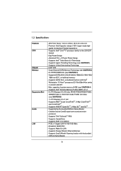
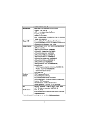
... Supports Untied Overclocking Technology - Broadcom BCM57781 - Supports DDR3 ECC, un-buffered memory with the bundled ASRock Game Blaster 6 Quad Channel DDR3 Memory Technology (see CAUTION 2) - 8 x DDR3 DIMM slots (... Efficient Ethernet 802.3az - Supports Intel® Turbo Boost 2.0 Technology - Intel® X79 - PCIE6: x8 mode) (see CAUTION 1) - ATX Form Factor: 12.0-in x 9.6-in socket...26xx/46xx series in , 30.5 cm x 24.4 cm - 1.2 Specifications Platform CPU Chipset Memory Expansion Slot Audio LAN - Advanced V16 + 2 Power Phase Design - Supports NVIDIA...
... Supports Untied Overclocking Technology - Broadcom BCM57781 - Supports DDR3 ECC, un-buffered memory with the bundled ASRock Game Blaster 6 Quad Channel DDR3 Memory Technology (see CAUTION 2) - 8 x DDR3 DIMM slots (... Efficient Ethernet 802.3az - Supports Intel® Turbo Boost 2.0 Technology - Intel® X79 - PCIE6: x8 mode) (see CAUTION 1) - ATX Form Factor: 12.0-in x 9.6-in socket...26xx/46xx series in , 30.5 cm x 24.4 cm - 1.2 Specifications Platform CPU Chipset Memory Expansion Slot Audio LAN - Advanced V16 + 2 Power Phase Design - Supports NVIDIA...

User Manual
Page 7
...2 x USB 3.0 headers (support 4 USB 3.0 ports) - 1 x Dr. Debug with LED - 1 x Clear CMOS Switch with LED - 1 x Power Switch with LED - 2 x SATA3 6.0 Gb/s connectors by Intel® X79, support RAID (RAID 0, RAID 1, RAID 5, RAID 10 and Intel Rapid Storage 3.0), NCQ, AHCI and "Hot Plug" functions - 2 x SATA3 6.0 Gb/s connectors by Marvell SE9220, support RAID...to-Use USB 3.0 Ports - 1 x RJ-45 LAN Port with LED (ACT/LINK LED and SPEED LED) - 1 x IEEE 1394 Port - 1 x Clear CMOS Switch with LED 7 CPU/Chassis/Power/SB FAN connector - 24 pin ATX power connector - 2 x 8 pin 12V power connectors -
...2 x USB 3.0 headers (support 4 USB 3.0 ports) - 1 x Dr. Debug with LED - 1 x Clear CMOS Switch with LED - 1 x Power Switch with LED - 2 x SATA3 6.0 Gb/s connectors by Intel® X79, support RAID (RAID 0, RAID 1, RAID 5, RAID 10 and Intel Rapid Storage 3.0), NCQ, AHCI and "Hot Plug" functions - 2 x SATA3 6.0 Gb/s connectors by Marvell SE9220, support RAID...to-Use USB 3.0 Ports - 1 x RJ-45 LAN Port with LED (ACT/LINK LED and SPEED LED) - 1 x IEEE 1394 Port - 1 x Clear CMOS Switch with LED 7 CPU/Chassis/Power/SB FAN connector - 24 pin ATX power connector - 2 x 8 pin 12V power connectors -
User Manual
Page 8
... - Drivers, Utilities, AntiVirus Software (Trial Version), CyberLink MediaEspresso 6.5 Trial, ASRock Software Suite (ASRock MAGIX Multimedia Suite - OEM) Unique Feature - ASRock Instant Boot - ASRock XFast LAN (see CAUTION 6) - CPU/Chassis/Power/SB Fan Tachometer - Adjust by CPU Temperature) - Supports "Plug and Play" - Supports jumperfree - CPU, VCCSA, DRAM, VTT, CPU PLL, PCH1.1V, PCH1.5V Voltage Multi-adjustment Support CD...
... - Drivers, Utilities, AntiVirus Software (Trial Version), CyberLink MediaEspresso 6.5 Trial, ASRock Software Suite (ASRock MAGIX Multimedia Suite - OEM) Unique Feature - ASRock Instant Boot - ASRock XFast LAN (see CAUTION 6) - CPU/Chassis/Power/SB Fan Tachometer - Adjust by CPU Temperature) - Supports "Plug and Play" - Supports jumperfree - CPU, VCCSA, DRAM, VTT, CPU PLL, PCH1.1V, PCH1.5V Voltage Multi-adjustment Support CD...
User Manual
Page 9
...interface, which includes Hardware Monitor, Fan Control, Overclocking, OC DNA and IES. ASRock Extreme Tuning Utility (AXTU) is a certain risk involved with overclocking, including adjusting the setting in -one tool to Intel® CPU spec definition, please install the memory modules on page 21 for the fi...For Windows® OS with your OC settings as a profile and share it with 64-bit CPU, there is already PCIE 3.0 hardware ready. Your friends then can use ASRock XFast RAM to DDR3_ C2.) 4. CAUTION! 1. Please check Intel's website for the operation procedures of your ...
...interface, which includes Hardware Monitor, Fan Control, Overclocking, OC DNA and IES. ASRock Extreme Tuning Utility (AXTU) is a certain risk involved with overclocking, including adjusting the setting in -one tool to Intel® CPU spec definition, please install the memory modules on page 21 for the fi...For Windows® OS with your OC settings as a profile and share it with 64-bit CPU, there is already PCIE 3.0 hardware ready. Your friends then can use ASRock XFast RAM to DDR3_ C2.) 4. CAUTION! 1. Please check Intel's website for the operation procedures of your ...
User Manual
Page 11
... BIOS will remain deactivated to check with the power supply manufacturer for the completed system. Frequencies other than ever. While CPU overheat is included into ASRock Extreme Tuning Utility (AXTU). And it back again. Although this feature. 16. To improve heat dissipation, remember to EuP, ...of previously visited websites, making web surfing faster than the recommended CPU bus frequencies may cause instability of failing. ASRock Crashless BIOS allows users to extend their BIOS without fear of the system or damage the CPU. 17. Please note that cannot be placed in the root...
... BIOS will remain deactivated to check with the power supply manufacturer for the completed system. Frequencies other than ever. While CPU overheat is included into ASRock Extreme Tuning Utility (AXTU). And it back again. Although this feature. 16. To improve heat dissipation, remember to EuP, ...of previously visited websites, making web surfing faster than the recommended CPU bus frequencies may cause instability of failing. ASRock Crashless BIOS allows users to extend their BIOS without fear of the system or damage the CPU. 17. Please note that cannot be placed in the root...
User Manual
Page 12
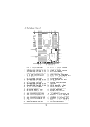
... 3.0 T: USB2 B: USB3 eSATA3 eSATA3 SLI/XFIRE_PWR1 USB 3.0 SATA3 6Gb/s ErP/EuP Ready 50 SB_FAN1 USB3_6_7 2 oz Copper PCB 49 PCIE1 LAN PHY X79 Extreme9 1 USB3_4_5 1 48 PCIE2 SATA2_2_3 SATA2_0_1 47 46 45 44 SATA3_0_1 SATA3_M4_M5 Super I/O PCIE3 Front USB 3.0 CMOS Battery PCIE4 X X Fast USB Fast LAN... DDR3 DIMM Slot (DDR3_D2, Black) 36 USB 2.0 Header (USB_10_11, Black) 11 240-pin DDR3 DIMM Slot (DDR3_D1, Black) 37 Intel X79 Chipset 12 CPU Fan Connector (CPU_FAN2) 38 Consumer Infrared Module Header 13 240-pin DDR3 DIMM Slot (DDR3_C2, Black) (CIR1, Gray) 14 240-pin DDR3...
... 3.0 T: USB2 B: USB3 eSATA3 eSATA3 SLI/XFIRE_PWR1 USB 3.0 SATA3 6Gb/s ErP/EuP Ready 50 SB_FAN1 USB3_6_7 2 oz Copper PCB 49 PCIE1 LAN PHY X79 Extreme9 1 USB3_4_5 1 48 PCIE2 SATA2_2_3 SATA2_0_1 47 46 45 44 SATA3_0_1 SATA3_M4_M5 Super I/O PCIE3 Front USB 3.0 CMOS Battery PCIE4 X X Fast USB Fast LAN... DDR3 DIMM Slot (DDR3_D2, Black) 36 USB 2.0 Header (USB_10_11, Black) 11 240-pin DDR3 DIMM Slot (DDR3_D1, Black) 37 Intel X79 Chipset 12 CPU Fan Connector (CPU_FAN2) 38 Consumer Infrared Module Header 13 240-pin DDR3 DIMM Slot (DDR3_C2, Black) (CIR1, Gray) 14 240-pin DDR3...

User Manual
Page 18
... the socket if above situation is unclean or if there are any bent pins in order to insert the CPU into the socket, please check if the CPU surface is found. Open the socket: Step 1-1. Step 1-3. Disengage the left lever by pressing it down and sliding it out of the hook. ...Step 2-1. Step 1-2. Keep the right lever positioned at about 90 degrees in the socket. Otherwise, the CPU will be seriously damaged. Hold the CPU by pressing it down and sliding it out of Intel 2011-Pin CPU, please follow the steps below. Do not force to flip up the load plate. Step...
... the socket if above situation is unclean or if there are any bent pins in order to insert the CPU into the socket, please check if the CPU surface is found. Open the socket: Step 1-1. Step 1-3. Disengage the left lever by pressing it down and sliding it out of the hook. ...Step 2-1. Step 1-2. Keep the right lever positioned at about 90 degrees in the socket. Otherwise, the CPU will be seriously damaged. Hold the CPU by pressing it down and sliding it out of Intel 2011-Pin CPU, please follow the steps below. Do not force to flip up the load plate. Step...

User Manual
Page 19
... the socket: Step 3-1. Press down the left load lever, and secure it with the load plate tab under the retention tab. Step 3-3. Carefully place the CPU into the socket by itself. Step 3-2. Step 2-3. Step 3. Step 2-4. The cover must be placed if returning the motherboard for after service. Flip the load plate... lever, and secure it with the load plate tab under the retention tab. 19 orientation key notch Pin1 alignment key orientation key notch 2011-Pin CPU alignment key 2011-Pin Socket For proper inserting, please ensure to the orient keys.
... the socket: Step 3-1. Press down the left load lever, and secure it with the load plate tab under the retention tab. Step 3-3. Carefully place the CPU into the socket by itself. Step 3-2. Step 2-3. Step 3. Step 2-4. The cover must be placed if returning the motherboard for after service. Flip the load plate... lever, and secure it with the load plate tab under the retention tab. 19 orientation key notch Pin1 alignment key orientation key notch 2011-Pin CPU alignment key 2011-Pin Socket For proper inserting, please ensure to the orient keys.

User Manual
Page 20
...are securely fastened and in good contact with tie-wrap to dissipate heat. Below is equipped with 2011-Pin socket that the CPU and the heatsink are oriented on the motherboard. For proper installation, please kindly refer to illustrate the installation of heatsink and ...cooling fan compliant with Intel 2011Pin CPU to ensure the cable does not interfere with the motherboard's holes. Apply Thermal Interface Material Step 2. Secure excess cable with each ...
...are securely fastened and in good contact with tie-wrap to dissipate heat. Below is equipped with 2011-Pin socket that the CPU and the heatsink are oriented on the motherboard. For proper installation, please kindly refer to illustrate the installation of heatsink and ...cooling fan compliant with Intel 2011Pin CPU to ensure the cable does not interfere with the motherboard's holes. Apply Thermal Interface Material Step 2. Secure excess cable with each ...

User Manual
Page 21
... DIMM slots, then Quad Channel Memory Technology is activated. If more than four memory modules are fully installed, and you always need to Intel® CPU spec definition, please install the memory modules on DDR3_A1, DDR3_B1, DDR3_C1 and DDR3_D1 for the first priority. otherwise, this motherboard and DIMM...
... DIMM slots, then Quad Channel Memory Technology is activated. If more than four memory modules are fully installed, and you always need to Intel® CPU spec definition, please install the memory modules on DDR3_A1, DDR3_B1, DDR3_C1 and DDR3_D1 for the first priority. otherwise, this motherboard and DIMM...

User Manual
Page 23
...slots. PCIE3 (PCIE 2.0 x1 slot) is recommended to install a PCI Express x16 graphics card on Intel's CPU to motherboard chassis fan connector (CHA_FAN1, CHA_FAN2 or CHA_FAN3) when using multiple graphics cards for better thermal environment. ...'t support PCIE 3.0, but this motherboard. If you install five PCI Express x16 graphics cards on future CPU updates and releases. 23 Please check Intel's website for information on PCIE1, PCIE2, PCIE4, PCIE5 and PCIE6 ... for PCI Express cards with x1 lane width cards, such as ASRock Game Blaster, Gigabit LAN card, SATA2 card, etc.
...slots. PCIE3 (PCIE 2.0 x1 slot) is recommended to install a PCI Express x16 graphics card on Intel's CPU to motherboard chassis fan connector (CHA_FAN1, CHA_FAN2 or CHA_FAN3) when using multiple graphics cards for better thermal environment. ...'t support PCIE 3.0, but this motherboard. If you install five PCI Express x16 graphics cards on future CPU updates and releases. 23 Please check Intel's website for information on PCIE1, PCIE2, PCIE4, PCIE5 and PCIE6 ... for PCI Express cards with x1 lane width cards, such as ASRock Game Blaster, Gigabit LAN card, SATA2 card, etc.

User Manual
Page 51
... still can work successfully even without the fan speed control function. The LED is operating. If you plan to connect the 3-Pin CPU fan to the CPU fan connector on when the system is off ). Pin 1-3 Connected 3-Pin Fan Installation (3-pin CPU_FAN2) (see p.12 No. 9) FAN_SPEED_CONTROL CPU_FAN_SPEED...CHA_FAN3 support FAN control. SB_FAN1 supports Quiet FAN. (3-pin PWR_FAN1) (see p.12 No. 1) (3-pin SB_FAN1) (see p.12 No. 16) GND +12V SB_FAN_SPEED CPU Fan Connectors (4-pin CPU_FAN1) (see p.12 No. 12) GND +12V CPU_FAN_SPEED 51 Power LED Header (3-pin PLED1) (see p.12 No. 31) 1 PLEDPLED...
... still can work successfully even without the fan speed control function. The LED is operating. If you plan to connect the 3-Pin CPU fan to the CPU fan connector on when the system is off ). Pin 1-3 Connected 3-Pin Fan Installation (3-pin CPU_FAN2) (see p.12 No. 9) FAN_SPEED_CONTROL CPU_FAN_SPEED...CHA_FAN3 support FAN control. SB_FAN1 supports Quiet FAN. (3-pin PWR_FAN1) (see p.12 No. 1) (3-pin SB_FAN1) (see p.12 No. 16) GND +12V SB_FAN_SPEED CPU Fan Connectors (4-pin CPU_FAN1) (see p.12 No. 12) GND +12V CPU_FAN_SPEED 51 Power LED Header (3-pin PLED1) (see p.12 No. 31) 1 PLEDPLED...

User Manual
Page 55
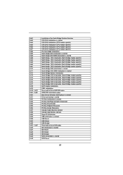
...found Microcode not loaded PEI Core is started Pre-memory CPU initialization is started Pre-memory CPU initialization (CPU module specific) Pre-memory CPU initialization (CPU module specific) Pre-memory CPU initialization (CPU module specific) Pre-memory North Bridge initialization is ... specific) Pre-Memory North Bridge initialization (North Bridge module specific) Pre-memory South Bridge initialization is started CPU post-memory initialization. Configuring memory Memory initialization (other) Reserved for reading the Dr. Debug codes. Serial Presence...
...found Microcode not loaded PEI Core is started Pre-memory CPU initialization is started Pre-memory CPU initialization (CPU module specific) Pre-memory CPU initialization (CPU module specific) Pre-memory CPU initialization (CPU module specific) Pre-memory North Bridge initialization is ... specific) Pre-Memory North Bridge initialization (North Bridge module specific) Pre-memory South Bridge initialization is started CPU post-memory initialization. Configuring memory Memory initialization (other) Reserved for reading the Dr. Debug codes. Serial Presence...

User Manual
Page 56
... usable memory detected Unspecified memory initialization error Memory not installed Invalid CPU type or Speed CPU mismatch CPU self test failed or possible CPU cache error CPU micro-code is not found or micro-code update is failed Internal CPU error reset PPI is not available Reserved for future AMI error codes S3 Resume...
... usable memory detected Unspecified memory initialization error Memory not installed Invalid CPU type or Speed CPU mismatch CPU self test failed or possible CPU cache error CPU micro-code is not found or micro-code update is failed Internal CPU error reset PPI is not available Reserved for future AMI error codes S3 Resume...
User Manual
Page 57
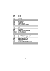
... - 0x9F 0xA0 0xA1 0xA2 0xA3 0xA4 0xA5 Installation of the South Bridge Runtime Services CPU DXE initialization is started CPU DXE initialization (CPU module specific) CPU DXE initialization (CPU module specific) CPU DXE initialization (CPU module specific) CPU DXE initialization (CPU module specific) PCI host bridge initialization North Bridge DXE initialization is started North Bridge...
... - 0x9F 0xA0 0xA1 0xA2 0xA3 0xA4 0xA5 Installation of the South Bridge Runtime Services CPU DXE initialization is started CPU DXE initialization (CPU module specific) CPU DXE initialization (CPU module specific) CPU DXE initialization (CPU module specific) CPU DXE initialization (CPU module specific) PCI host bridge initialization North Bridge DXE initialization is started North Bridge...
User Manual
Page 58
... PCI bus hot plug Clean-up of NVRAM Configuration Reset (reset of NVRAM settings) Reserved for future AMI codes OEM BDS initialization codes CPU initialization error North Bridge initialization error South Bridge initialization error Some of Resources No Space for Legacy Option ROM No Console Output Devices are found...
... PCI bus hot plug Clean-up of NVRAM Configuration Reset (reset of NVRAM settings) Reserved for future AMI codes OEM BDS initialization codes CPU initialization error North Bridge initialization error South Bridge initialization error Some of Resources No Space for Legacy Option ROM No Console Output Devices are found...

User Manual
Page 72
...Overvoltage Use this item to enable power savings. Processor can switch between multiple frequency and voltage points to enable/disable CPU Internal PLL Overvoltage Function. CPU Control CPU Ratio Setting Use this item to run faster than marked frequency in OS level. Intel SpeedStep Technology Intel SpeedStep ...ratio value of this motherboard. The default value is Intel's new power saving technology. Intel Turbo Mode Technology Use this item to load CPU EZ overclocking settings. 3.3 OC Tweaker Screen In the OC Tweaker screen, you install Windows® VistaTM / 7 and want to ...
...Overvoltage Use this item to enable power savings. Processor can switch between multiple frequency and voltage points to enable/disable CPU Internal PLL Overvoltage Function. CPU Control CPU Ratio Setting Use this item to run faster than marked frequency in OS level. Intel SpeedStep Technology Intel SpeedStep ...ratio value of this motherboard. The default value is Intel's new power saving technology. Intel Turbo Mode Technology Use this item to load CPU EZ overclocking settings. 3.3 OC Tweaker Screen In the OC Tweaker screen, you install Windows® VistaTM / 7 and want to ...


