
User Manual
Page 2
... or product. Operation is subject to the following two conditions: (1) this device may not cause harmful interference, and (2) this motherboard contains Perchlorate, a toxic substance controlled in Perchlorate Best Management Practices (BMP) regulations passed by the California Legislature. Copyright Notice: ...either expressed or implied, including but not limited to change without notice, and should not be constructed as a commitment by ASRock. CALIFORNIA, USA ONLY The Lithium battery adopted on this device must accept any indirect, special, incidental, or consequential damages (...
... or product. Operation is subject to the following two conditions: (1) this device may not cause harmful interference, and (2) this motherboard contains Perchlorate, a toxic substance controlled in Perchlorate Best Management Practices (BMP) regulations passed by the California Legislature. Copyright Notice: ...either expressed or implied, including but not limited to change without notice, and should not be constructed as a commitment by ASRock. CALIFORNIA, USA ONLY The Lithium battery adopted on this device must accept any indirect, special, incidental, or consequential damages (...
User Manual
Page 3
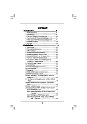
... 1 Introduction 5 1.1 Package Contents 5 1.2 Specifications 6 1.3 Two SLITM Graphics Card Support List 10 1.4 Two CrossFireXTM Graphics Card Support List 11 1.5 Three CrossFireXTM Graphics Card Support List .......... 11 1.6 Motherboard Layout 12 1.7 I/O Panel 13 2 Installation 14 2.1 Screw Holes 14 2.2 Pre-installation Precautions 14 2.3 CPU Installation 15 2.4 Installation of Heatsink and CPU fan 17 2.5 Installation of...
... 1 Introduction 5 1.1 Package Contents 5 1.2 Specifications 6 1.3 Two SLITM Graphics Card Support List 10 1.4 Two CrossFireXTM Graphics Card Support List 11 1.5 Three CrossFireXTM Graphics Card Support List .......... 11 1.6 Motherboard Layout 12 1.7 I/O Panel 13 2 Installation 14 2.1 Screw Holes 14 2.2 Pre-installation Precautions 14 2.3 CPU Installation 15 2.4 Installation of Heatsink and CPU fan 17 2.5 Installation of...
User Manual
Page 5
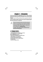
... Cables (Optional) 1 x I/O Panel Shield 1 x ASRock SLI_Bridge_2S Card 5 www.asrock.com/support/index.asp 1.1 Package Contents ASRock X58 Extreme Motherboard (ATX Form Factor: 12.0-in x 9.6-in, 30.5 cm x 24.4 cm) ASRock X58 Extreme Quick Installation Guide ASRock X58 Extreme Support CD 1 x 80-conductor Ultra ATA 66/100/133 IDE Ribbon Cable 1 x Ribbon Cable for purchasing ASRock X58 Extreme motherboard, a reliable motherboard produced under ASRock's consistently stringent quality control. Because...
... Cables (Optional) 1 x I/O Panel Shield 1 x ASRock SLI_Bridge_2S Card 5 www.asrock.com/support/index.asp 1.1 Package Contents ASRock X58 Extreme Motherboard (ATX Form Factor: 12.0-in x 9.6-in, 30.5 cm x 24.4 cm) ASRock X58 Extreme Quick Installation Guide ASRock X58 Extreme Support CD 1 x 80-conductor Ultra ATA 66/100/133 IDE Ribbon Cable 1 x Ribbon Cable for purchasing ASRock X58 Extreme motherboard, a reliable motherboard produced under ASRock's consistently stringent quality control. Because...
User Manual
Page 8
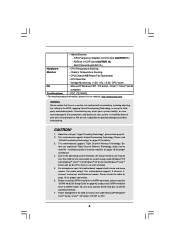
CPU Frequency Stepless Control (see CAUTION 12) - FCC, CE, WHQL * For detailed product information, please visit our website: http://www.asrock.com WARNING Please realize that there is no such limitation. 5. This motherboard supports Triple Channel Memory Technology. Chassis Temperature Sensing - Microsoft® Windows® XP / XP 64-bit / VistaTM / VistaTM 64-bit...
CPU Frequency Stepless Control (see CAUTION 12) - FCC, CE, WHQL * For detailed product information, please visit our website: http://www.asrock.com WARNING Please realize that there is no such limitation. 5. This motherboard supports Triple Channel Memory Technology. Chassis Temperature Sensing - Microsoft® Windows® XP / XP 64-bit / VistaTM / VistaTM 64-bit...
User Manual
Page 9
... Flash is detected, the system will automatically shutdown. Please be noted that delivers unparalleled power savings. ASRock website: http://www.asrock.com 10. Although this motherboard offers stepless control, it is able to perform over-clocking. Please visit our website for the operation procedures of the ...system or damage the CPU. 12. It is a user-friendly ASRock overclocking tool which allows you resume the system, please check if the CPU fan on the motherboard functions properly and unplug the power cord, then plug it is not recommended to provide...
... Flash is detected, the system will automatically shutdown. Please be noted that delivers unparalleled power savings. ASRock website: http://www.asrock.com 10. Although this motherboard offers stepless control, it is able to perform over-clocking. Please visit our website for the operation procedures of the ...system or damage the CPU. 12. It is a user-friendly ASRock overclocking tool which allows you resume the system, please check if the CPU fan on the motherboard functions properly and unplug the power cord, then plug it is not recommended to provide...
User Manual
Page 12
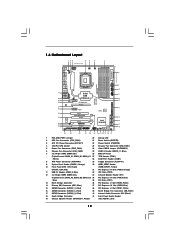
1.6 Motherboard Layout 123 45 6 7 24.4cm (9.6 in) PS2 Mouse PS2 Keyboard Clr CMOS 1 PS2_USB_PWR1 ATX12V1 PWR_FAN1 CHA_FAN2 8 CPU_FAN1 30.5cm (12.0 in) ATXPWR1 Coaxial SPDIF Optical ... PCIE1 13 PHY 38 PCI Express 2.0 CrossFireX QPI 6.4GT/s 37 36 AUDIO CODEC PCIE2 PCIE3 RoHS 14 1394a VIA VT6330 SATAII_5_6 SATAII_3_4 SATAII_1_2 35 PCI1 X58 Extreme 8Mb BIOS 34 PCIE4 IDE1 15 33 32 31 Super I/O 1 IR1 FLOPPY1 HDMI_SPDIF1 1 PCI2 PCIE5 COM1 1 1 TPM1 CMOS Battery Intel ICH10R USB10_11 CHA_FAN1 Debug CLRCMOS1...
1.6 Motherboard Layout 123 45 6 7 24.4cm (9.6 in) PS2 Mouse PS2 Keyboard Clr CMOS 1 PS2_USB_PWR1 ATX12V1 PWR_FAN1 CHA_FAN2 8 CPU_FAN1 30.5cm (12.0 in) ATXPWR1 Coaxial SPDIF Optical ... PCIE1 13 PHY 38 PCI Express 2.0 CrossFireX QPI 6.4GT/s 37 36 AUDIO CODEC PCIE2 PCIE3 RoHS 14 1394a VIA VT6330 SATAII_5_6 SATAII_3_4 SATAII_1_2 35 PCI1 X58 Extreme 8Mb BIOS 34 PCIE4 IDE1 15 33 32 31 Super I/O 1 IR1 FLOPPY1 HDMI_SPDIF1 1 PCI2 PCIE5 COM1 1 1 TPM1 CMOS Battery Intel ICH10R USB10_11 CHA_FAN1 Debug CLRCMOS1...
User Manual
Page 14
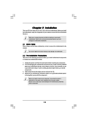
...of the following precautions before touching any component. 2. Hold components by circles to secure the motherboard to the chassis. Whenever you and damages to do not touch the ICs. 4. Failure to motherboard components. 2.1 Screw Holes Place screws into it on the carpet or the like. Make ...component, place it . Unplug the power cord from the power supply. To avoid damaging the motherboard components due to static electricity, NEVER place your chassis to ensure that the motherboard fits into the holes indicated by the edges and do so may cause physical injuries to ...
...of the following precautions before touching any component. 2. Hold components by circles to secure the motherboard to the chassis. Whenever you and damages to do not touch the ICs. 4. Failure to motherboard components. 2.1 Screw Holes Place screws into it on the carpet or the like. Make ...component, place it . Unplug the power cord from the power supply. To avoid damaging the motherboard components due to static electricity, NEVER place your chassis to ensure that the motherboard fits into the holes indicated by the edges and do so may cause physical injuries to ...
User Manual
Page 15
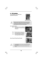
Otherwise, the CPU will be placed if returning the motherboard for after service. 15 Step 1-3. Do not force to clear retention tab. Step 1-2. Open the socket: Step 1-1. Disengaging the lever by depressing down and out ...
Otherwise, the CPU will be placed if returning the motherboard for after service. 15 Step 1-3. Do not force to clear retention tab. Step 1-2. Open the socket: Step 1-1. Disengaging the lever by depressing down and out ...
User Manual
Page 17
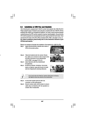
...thumb to install and lock. Before you installed the heatsink, you press down on fastener caps with the CPU fan connector on the motherboard. Place the heatsink onto the socket. Rotate the fastener clockwise, then press down the fasteners without rotating them clockwise, the heatsink .... Apply thermal interface material onto center of your CPU fan and heatsink. Step 5. Step 6. 2.4 Installation of CPU Fan and Heatsink This motherboard is an example to dissipate heat. Press Down (4 Places) If you need to spray thermal interface material between the CPU and the heatsink...
...thumb to install and lock. Before you installed the heatsink, you press down on fastener caps with the CPU fan connector on the motherboard. Place the heatsink onto the socket. Rotate the fastener clockwise, then press down the fasteners without rotating them clockwise, the heatsink .... Apply thermal interface material onto center of your CPU fan and heatsink. Step 5. Step 6. 2.4 Installation of CPU Fan and Heatsink This motherboard is an example to dissipate heat. Press Down (4 Places) If you need to spray thermal interface material between the CPU and the heatsink...
User Manual
Page 18
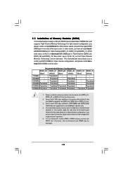
... or identical DDR3 DIMM pair in Triple Channel (DDR3_A2, DDR3_B2 and DDR3_C2; Populated 6 DIMMs Populated Populated Populated Populated Populated Populated 1. otherwise, this motherboard and DIMM may install varying memory sizes in the slots of the same color. White slots; Populated - - - - 2 DIMMs - Populated ...DDR3_A1, DDR3_B1 or DDR3_C1) for single-channel operation. 5. The system maps the total size of Memory Modules (DIMM) This motherboard provides six 240-pin DDR3 (Double Data Rate 3) DIMM slots, and supports Triple Channel Memory Technology. It is not ...
... or identical DDR3 DIMM pair in Triple Channel (DDR3_A2, DDR3_B2 and DDR3_C2; Populated 6 DIMMs Populated Populated Populated Populated Populated Populated 1. otherwise, this motherboard and DIMM may install varying memory sizes in the slots of the same color. White slots; Populated - - - - 2 DIMMs - Populated ...DDR3_A1, DDR3_B1 or DDR3_C1) for single-channel operation. 5. The system maps the total size of Memory Modules (DIMM) This motherboard provides six 240-pin DDR3 (Double Data Rate 3) DIMM slots, and supports Triple Channel Memory Technology. It is not ...
User Manual
Page 19
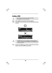
... outward. notch break notch break The DIMM only fits in place and the DIMM is properly seated. 19 Installing a DIMM Please make sure to the motherboard and the DIMM if you force the DIMM into the slot until the retaining clips at incorrect orientation. Step 2. It will cause permanent damage to...
... outward. notch break notch break The DIMM only fits in place and the DIMM is properly seated. 19 Installing a DIMM Please make sure to the motherboard and the DIMM if you force the DIMM into the slot until the retaining clips at incorrect orientation. Step 2. It will cause permanent damage to...
User Manual
Page 20
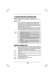
... card, SATA2 card, etc. Step 6. Orange) is unplugged. Please connect a chassis fan to install a PCI Express x16 graphics card on this motherboard. Replace the system cover. 20 Therefore, PCIE2 and PCIE4 slots will work at x16 bandwidth while PCIE5 slot will work at x16 bandwidth. 3. Step...for PCI Express x16 lane width graphics cards, or used to support 3-Way CrossFireXTM function. 1. Remove the system unit cover (if your motherboard is used for the card before you intend to support CrossFireXTM or SLITM function. PCI slots: PCI slots are 2 PCI slots and 5...
... card, SATA2 card, etc. Step 6. Orange) is unplugged. Please connect a chassis fan to install a PCI Express x16 graphics card on this motherboard. Replace the system cover. 20 Therefore, PCIE2 and PCIE4 slots will work at x16 bandwidth while PCIE5 slot will work at x16 bandwidth. 3. Step...for PCI Express x16 lane width graphics cards, or used to support 3-Way CrossFireXTM function. 1. Remove the system unit cover (if your motherboard is used for the card before you intend to support CrossFireXTM or SLITM function. PCI slots: PCI slots are 2 PCI slots and 5...
User Manual
Page 21
... graphics cards. 21 Install the identical SLITM-ready graphics cards that are properly seated on the slots. Step2. 2.7 SLITM and Quad SLITM Operation Guide This motherboard supports NVIDIA® SLITM and Quad SLITM (Scalable Link Interface) technology that allows you should have two identical SLITM-ready graphics cards that are NVIDIA...
... graphics cards. 21 Install the identical SLITM-ready graphics cards that are properly seated on the slots. Step2. 2.7 SLITM and Quad SLITM Operation Guide This motherboard supports NVIDIA® SLITM and Quad SLITM (Scalable Link Interface) technology that allows you should have two identical SLITM-ready graphics cards that are NVIDIA...
User Manual
Page 25
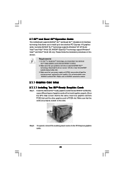
2.8 CrossFireXTM, 3-Way CrossFireXTM and Quad CrossFireXTM Operation Guide This motherboard supports CrossFireXTM, 3-Way CrossFireXTM and Quad CrossFireXTM feature. CrossFireXTM technology offers the most advantageous means available of performance and image quality in a ... may require different methods to benefit from the CrossFireXTM multi-GPU platform. 2. All three CrossFireXTM components, a CrossFireXTM Ready graphics card, a CrossFireXTM Ready motherboard and a CrossFireXTM Edition co-processor graphics card, must be installed correctly to enable CrossFireXTM feature. Step 1.
2.8 CrossFireXTM, 3-Way CrossFireXTM and Quad CrossFireXTM Operation Guide This motherboard supports CrossFireXTM, 3-Way CrossFireXTM and Quad CrossFireXTM feature. CrossFireXTM technology offers the most advantageous means available of performance and image quality in a ... may require different methods to benefit from the CrossFireXTM multi-GPU platform. 2. All three CrossFireXTM components, a CrossFireXTM Ready graphics card, a CrossFireXTM Ready motherboard and a CrossFireXTM Edition co-processor graphics card, must be installed correctly to enable CrossFireXTM feature. Step 1.
User Manual
Page 26
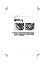
... the Radeon graphics card on the top of Radeon graphics cards. (CrossFire Bridge is provided with the graphics card you purchase, not bundled with this motherboard. Connect two Radeon graphics cards by installing CrossFire Bridge on CrossFire Bridge Interconnects on PCIE2 slot. (You may use the DVI to D-Sub adapter to...
... the Radeon graphics card on the top of Radeon graphics cards. (CrossFire Bridge is provided with the graphics card you purchase, not bundled with this motherboard. Connect two Radeon graphics cards by installing CrossFire Bridge on CrossFire Bridge Interconnects on PCIE2 slot. (You may use the DVI to D-Sub adapter to...
User Manual
Page 27
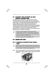
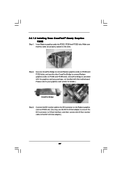
... Bridge to connect Radeon graphics cards on PCIE4 and PCIE5 slots. (CrossFire Bridge is provided with the graphics card you purchase, not bundled with this motherboard. 2.8.1.2 Installing Three CrossFireXTM-Ready Graphics Cards Step 1. Make sure that the cards are properly seated on PCIE2 and PCIE4 slots, and use the DVI to...
... Bridge to connect Radeon graphics cards on PCIE4 and PCIE5 slots. (CrossFire Bridge is provided with the graphics card you purchase, not bundled with this motherboard. 2.8.1.2 Installing Three CrossFireXTM-Ready Graphics Cards Step 1. Make sure that the cards are properly seated on PCIE2 and PCIE4 slots, and use the DVI to...
User Manual
Page 30
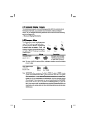
... parameters. To clear and reset the system parameters to clear the data in CMOS. However, please do the clearCMOS action. 30 2.9 Surround Display Feature This motherboard supports Surround Display upgrade. If no jumper cap is placed on pins, the jumper is placed on CLRCMOS1 for PS/2 +5V +5VSB or USB wake...
... parameters. To clear and reset the system parameters to clear the data in CMOS. However, please do the clearCMOS action. 30 2.9 Surround Display Feature This motherboard supports Surround Display upgrade. If no jumper cap is placed on pins, the jumper is placed on CLRCMOS1 for PS/2 +5V +5VSB or USB wake...
User Manual
Page 31
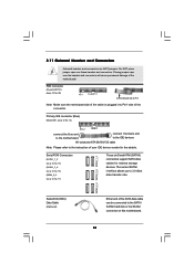
... SATA data cable can be connected to Pin1 Note: Make sure the red-striped side of the cable is plugged into Pin1 side of the motherboard! Serial ATAII Connectors (SATAII_1_2: see p.12, No. 15) (SATAII_3_4: see p.12, No. 16) (SATAII_5_6: see p.12 No. 29) Pin1 FLOPPY1 the red-striped side... to the SATA / SATAII hard disk or the SATAII connector on this motherboard. 31 FDD connector (33-pin FLOPPY1) (see p.12, No. 17) These six Serial ATAII (SATAII) connectors support SATA data cables for the details. Placing ...
... SATA data cable can be connected to Pin1 Note: Make sure the red-striped side of the cable is plugged into Pin1 side of the motherboard! Serial ATAII Connectors (SATAII_1_2: see p.12, No. 15) (SATAII_3_4: see p.12, No. 16) (SATAII_5_6: see p.12 No. 29) Pin1 FLOPPY1 the red-striped side... to the SATA / SATAII hard disk or the SATAII connector on this motherboard. 31 FDD connector (33-pin FLOPPY1) (see p.12, No. 17) These six Serial ATAII (SATAII) connectors support SATA data cables for the details. Placing ...
User Manual
Page 32
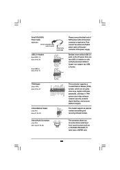
... PWRDWN GND NC LAD2 LAD1 GND NC SERIRQ CLKRUN NC Please connect the black end of SATA power cable to the power connector on this motherboard.
... PWRDWN GND NC LAD2 LAD1 GND NC SERIRQ CLKRUN NC Please connect the black end of SATA power cable to the power connector on this motherboard.
User Manual
Page 34
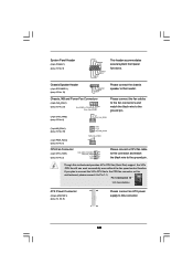
... and match the black wire to the ground pin. If you plan to connect the 3-Pin CPU fan to the CPU fan connector on this motherboard, please connect it to this header. Chassis, NB and Power Fan Connectors (4-pin CHA_FAN1) (see p.12 No. 23) FAN_SPEED_CONTROL GND +12V CHA_FAN_SPEED (3-pin... CHA_FAN2) (see p.12 No. 6) GND +12V CHA_FAN_SPEED Please connect the fan cables to the fan connectors and match the black wire to this motherboard provides 4-Pin CPU fan (Quiet Fan) support, the 3-Pin CPU fan still can work successfully even without the fan speed control function. Chassis Speaker...
... and match the black wire to the ground pin. If you plan to connect the 3-Pin CPU fan to the CPU fan connector on this motherboard, please connect it to this header. Chassis, NB and Power Fan Connectors (4-pin CHA_FAN1) (see p.12 No. 23) FAN_SPEED_CONTROL GND +12V CHA_FAN_SPEED (3-pin... CHA_FAN2) (see p.12 No. 6) GND +12V CHA_FAN_SPEED Please connect the fan cables to the fan connectors and match the black wire to this motherboard provides 4-Pin CPU fan (Quiet Fan) support, the 3-Pin CPU fan still can work successfully even without the fan speed control function. Chassis Speaker...


