
User Manual
Page 1
All rights reserved. 1 X58 Extreme User Manual Version 1.1 Published July 2009 Copyright©2009 ASRock INC.
All rights reserved. 1 X58 Extreme User Manual Version 1.1 Published July 2009 Copyright©2009 ASRock INC.
User Manual
Page 2
With respect to the contents of this manual, ASRock does not provide warranty of any kind, either expressed or implied, including but not limited to infringe. This device complies with Part 15 of ASRock Inc. ASRock assumes no event shall ASRock, its directors, officers, employees, or agents ... may apply, see www.dtsc.ca.gov/hazardouswaste/perchlorate" ASRock Website: http://www.asrock.com 2 Operation is subject to the following two conditions: (1) this device may not cause harmful interference, and (2) this manual are furnished for informational use only and subject to change ...
With respect to the contents of this manual, ASRock does not provide warranty of any kind, either expressed or implied, including but not limited to infringe. This device complies with Part 15 of ASRock Inc. ASRock assumes no event shall ASRock, its directors, officers, employees, or agents ... may apply, see www.dtsc.ca.gov/hazardouswaste/perchlorate" ASRock Website: http://www.asrock.com 2 Operation is subject to the following two conditions: (1) this device may not cause harmful interference, and (2) this manual are furnished for informational use only and subject to change ...
User Manual
Page 5
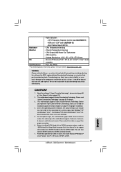
... 1 and 2 contain introduction of the Support CD. In this manual will be subject to quality and endurance. www.asrock.com/support/index.asp 1.1 Package Contents ASRock X58 Extreme Motherboard (ATX Form Factor: 12.0-in x 9.6-in, 30.5 cm x 24.4 cm) ASRock X58 Extreme Quick Installation Guide ASRock X58 Extreme Support CD 1 x 80-conductor Ultra ATA 66/100/133 IDE Ribbon Cable 1 x Ribbon...
... 1 and 2 contain introduction of the Support CD. In this manual will be subject to quality and endurance. www.asrock.com/support/index.asp 1.1 Package Contents ASRock X58 Extreme Motherboard (ATX Form Factor: 12.0-in x 9.6-in, 30.5 cm x 24.4 cm) ASRock X58 Extreme Quick Installation Guide ASRock X58 Extreme Support CD 1 x 80-conductor Ultra ATA 66/100/133 IDE Ribbon Cable 1 x Ribbon...
User Manual
Page 17
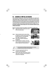
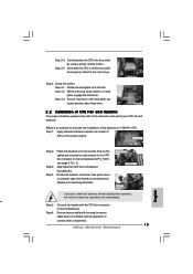
... of IHS on the motherboard. Step 4. Repeat with the motherboard Fastener slots pointing straight out throughholes. Secure excess cable with tie-wrap to the instruction manuals of your CPU fan and heatsink. For proper installation, please kindly refer to ensure cable does not interfere with thumb to illustrate the installation of...
... of IHS on the motherboard. Step 4. Repeat with the motherboard Fastener slots pointing straight out throughholes. Secure excess cable with tie-wrap to the instruction manuals of your CPU fan and heatsink. For proper installation, please kindly refer to ensure cable does not interfere with thumb to illustrate the installation of...
User Manual
Page 25
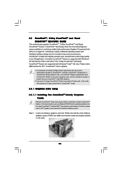
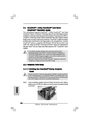
... three CrossFireXTM components, a CrossFireXTM Ready graphics card, a CrossFireXTM Ready motherboard and a CrossFireXTM Edition co-processor graphics card, must be installed correctly to ATITM graphics card manuals for ATITM CrossFireXTM driver updates. 1. For other Radeon graphics card to enable CrossFireXTM feature. Make sure that ATITM has released or will not see the...
... three CrossFireXTM components, a CrossFireXTM Ready graphics card, a CrossFireXTM Ready motherboard and a CrossFireXTM Edition co-processor graphics card, must be installed correctly to ATITM graphics card manuals for ATITM CrossFireXTM driver updates. 1. For other Radeon graphics card to enable CrossFireXTM feature. Make sure that ATITM has released or will not see the...
User Manual
Page 33
... you use AC'97 audio panel, please install it to make the Front Mic as default record device. Please follow the instruction in our manual and chassis manual to hear your system. 2. Connect Audio_R (RIN) to OUT2_R and Audio_L (LIN) to [Enabled]. D. Enter BIOS Setup Utility. Enter Advanced Settings, and then select...
... you use AC'97 audio panel, please install it to make the Front Mic as default record device. Please follow the instruction in our manual and chassis manual to hear your system. 2. Connect Audio_R (RIN) to OUT2_R and Audio_L (LIN) to [Enabled]. D. Enter BIOS Setup Utility. Enter Advanced Settings, and then select...
User Manual
Page 39
... of KB/MS using AMI KB-5. Give control to CH-2 count reg. The POST code checkpoints are based on CMOS setup questions. Verify CMOS checksum manually by reading storage area. Install the POSTINT1Ch handler. Check CMOS diagnostic byte to "POSTINT1ChHandlerBlock." Initializes the CPU. Initialized CMOS as system timer. Initialize CH-0 as...
... of KB/MS using AMI KB-5. Give control to CH-2 count reg. The POST code checkpoints are based on CMOS setup questions. Verify CMOS checksum manually by reading storage area. Install the POSTINT1Ch handler. Check CMOS diagnostic byte to "POSTINT1ChHandlerBlock." Initializes the CPU. Initialized CMOS as system timer. Initialize CH-0 as...
User Manual
Page 41
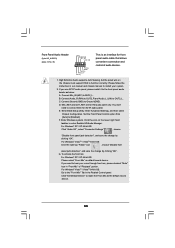
... system to page 35. For the pin definition of HDMI_SPDIF cable to this picture shows the wrong example of connecting HDMI_SPDIF cable to the user manual of PCI Express VGA card. white end (2-pin) (B) white end (3-pin) (C) Step 4. Step 5. Connect the black end (A) of HDMI_SPDIF header and ... of HDTV and HDMI VGA card vendor for connector usage in advance. Please refer to the user manual of HDMI VGA card or other VGA card. Please refer to the VGA card user manual for detailed connection procedures. A complete HDMI system requires a HDMI VGA card and a HDMI ready ...
... system to page 35. For the pin definition of HDMI_SPDIF cable to this picture shows the wrong example of connecting HDMI_SPDIF cable to the user manual of PCI Express VGA card. white end (2-pin) (B) white end (3-pin) (C) Step 4. Step 5. Connect the black end (A) of HDMI_SPDIF header and ... of HDTV and HDMI VGA card vendor for connector usage in advance. Please refer to the user manual of HDMI VGA card or other VGA card. Please refer to the VGA card user manual for detailed connection procedures. A complete HDMI system requires a HDMI VGA card and a HDMI ready ...
User Manual
Page 45
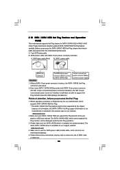
... SATA / SATAII Hot Plug cannot be damaged under the Hot Plug operation. 3. Make sure to power supply Caution 1. Make sure your dealer or HDD user manual. Before you process the Hot Plug: 1. SATA data cable (Red) B. Points of SATA / SATAII HDD Hot Plug feature carefully. A. 7-pin SATA data cable B. Even some... interfaces, the IDE 1x4-pin conventional power connector interface is designed only for SATA / SATAII HDD in the product spec on our support website: www.asrock.com 4. Please make sure the SATA / SATAII driver is available on our website: www...
... SATA / SATAII Hot Plug cannot be damaged under the Hot Plug operation. 3. Make sure to power supply Caution 1. Make sure your dealer or HDD user manual. Before you process the Hot Plug: 1. SATA data cable (Red) B. Points of SATA / SATAII HDD Hot Plug feature carefully. A. 7-pin SATA data cable B. Even some... interfaces, the IDE 1x4-pin conventional power connector interface is designed only for SATA / SATAII HDD in the product spec on our support website: www.asrock.com 4. Please make sure the SATA / SATAII driver is available on our website: www...

User Manual
Page 52
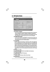
... RAID Functions If you enable Untied Overclocking function, please enter "Overclock Mode" option of BIOS setup to set the selection from [Auto] to [Manual]. page, please insert the ASRock Support CD into your system. Insert the Windows® VistaTM / VistaTM 64-bit optical disk into the optical drive again to boot your...
... RAID Functions If you enable Untied Overclocking function, please enter "Overclock Mode" option of BIOS setup to set the selection from [Auto] to [Manual]. page, please insert the ASRock Support CD into your system. Insert the Windows® VistaTM / VistaTM 64-bit optical disk into the optical drive again to boot your...
User Manual
Page 55
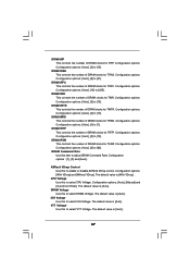
...Therefore, you are allowed to adjust the Host frequency and PCIE frequency in the following two items. If you select [Manual], Untied Overclocking function is enabled. Spread Spectrum This item should be [Auto] for the details of Boot Failure Guard. ...for better system stability. 55 BCLK Frequency (MHz) Use this option to adjust BCLK (Internal Base Clock) frequency. Configuration options: [Auto], [Manual], [I .O.T.] (Intelligent Overclocking Technology), the system will automatically enable the overclocking function when your own risk and expense. If you select [I ...
...Therefore, you are allowed to adjust the Host frequency and PCIE frequency in the following two items. If you select [Manual], Untied Overclocking function is enabled. Spread Spectrum This item should be [Auto] for the details of Boot Failure Guard. ...for better system stability. 55 BCLK Frequency (MHz) Use this option to adjust BCLK (Internal Base Clock) frequency. Configuration options: [Auto], [Manual], [I .O.T.] (Intelligent Overclocking Technology), the system will automatically enable the overclocking function when your own risk and expense. If you select [I ...
User Manual
Page 57
... is [With VDrop]. DRAM tRTP This controls the number of DRAM clocks for TWR. Configuration options : [1], [2] and [Auto]. ASRock VDrop Control Use this to enable or disable ASRock VDrop control. Configuration options: [Auto], [Manual] and [Overdrive Offset]. DRAM tRRD This controls the number of DRAM clocks for TRP. VTT Voltage Use this to...
... is [With VDrop]. DRAM tRTP This controls the number of DRAM clocks for TWR. Configuration options : [1], [2] and [Auto]. ASRock VDrop Control Use this to enable or disable ASRock VDrop control. Configuration options: [Auto], [Manual] and [Overdrive Offset]. DRAM tRRD This controls the number of DRAM clocks for TRP. VTT Voltage Use this to...
User Manual
Page 70
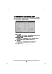
... FAN 2 Setting This allows you to set the chassis fan 1 speed. The default is value [Full On]. Configuration options: [Full On] and [Manual mode]. The default is value [Full On]. Chassis FAN 1 Setting This allows you to set the chassis fan 2 speed. NB FAN Setting This allows...parameters of the CPU temperature, motherboard temperature, CPU fan speed, chassis fan speed, and the critical voltage. Configuration options: [Full On] and [Manual mode]. The default is value [Full On]. 70 3.5 Hardware Health Event Monitoring Screen In this section, it allows you to set the NB fan...
... FAN 2 Setting This allows you to set the chassis fan 1 speed. The default is value [Full On]. Configuration options: [Full On] and [Manual mode]. The default is value [Full On]. Chassis FAN 1 Setting This allows you to set the chassis fan 2 speed. NB FAN Setting This allows...parameters of the CPU temperature, motherboard temperature, CPU fan speed, chassis fan speed, and the critical voltage. Configuration options: [Full On] and [Manual mode]. The default is value [Full On]. 70 3.5 Hardware Health Event Monitoring Screen In this section, it allows you to set the NB fan...
Quick Installation Guide
Page 4
... software might be updated, the content of the motherboard can be found in the user manual presented in Floppy Drive 4 x Serial ATA (SATA) Data Cables (Optional) 2 x Serial ATA (SATA) HDD Power Cables (Optional) 1 x I/O Panel Shield 1 x ASRock SLI_Bridge_2S Card 4 ASRock X58 Extreme Motherboard English You may find the latest VGA cards and CPU support lists on...
... software might be updated, the content of the motherboard can be found in the user manual presented in Floppy Drive 4 x Serial ATA (SATA) Data Cables (Optional) 2 x Serial ATA (SATA) HDD Power Cables (Optional) 1 x I/O Panel Shield 1 x ASRock SLI_Bridge_2S Card 4 ASRock X58 Extreme Motherboard English You may find the latest VGA cards and CPU support lists on...
Quick Installation Guide
Page 7
... to read the installation guide of "User Manual" in the support CD to adjust your SATAII hard disk drive to SATAII connector directly. 7. Please check the table on page 3 for details. 3. - ASRock U-COP (see CAUTION 11) - Chassis Temperature...Manual" in the BIOS, applying Untied Overclocking Technology, or using the thirdparty overclocking tools. Before installing SATAII hard disk to SATAII connector, please read "Untied Overclocking Technology" on page 14 for system usage under Microsoft® Windows® VistaTM 64-bit / VistaTM / XP 64-bit / XP SP1 or SP2. 7 ASRock X58 Extreme...
... to read the installation guide of "User Manual" in the support CD to adjust your SATAII hard disk drive to SATAII connector directly. 7. Please check the table on page 3 for details. 3. - ASRock U-COP (see CAUTION 11) - Chassis Temperature...Manual" in the BIOS, applying Untied Overclocking Technology, or using the thirdparty overclocking tools. Before installing SATAII hard disk to SATAII connector, please read "Untied Overclocking Technology" on page 14 for system usage under Microsoft® Windows® VistaTM 64-bit / VistaTM / XP 64-bit / XP SP1 or SP2. 7 ASRock X58 Extreme...
Quick Installation Guide
Page 13
... (CPU_FAN1, see page 2, No. 2). Repeat with the motherboard throughholes. Below is within the socket and properly mated to the instruction manuals of CPU Fan and Heatsink For proper installation, please kindly refer to the orient keys. Step 3. Rotate the fastener clockwise, then press... to the CPU fan connector on the socket surface. Secure excess cable with fan operation or contact other components. 13 ASRock X58 Extreme Motherboard English Rotate the load plate onto the IHS. Step 6. Close the socket: Step 4-1. Ensure fan cables are oriented on the...
... (CPU_FAN1, see page 2, No. 2). Repeat with the motherboard throughholes. Below is within the socket and properly mated to the instruction manuals of CPU Fan and Heatsink For proper installation, please kindly refer to the orient keys. Step 3. Rotate the fastener clockwise, then press... to the CPU fan connector on the socket surface. Secure excess cable with fan operation or contact other components. 13 ASRock X58 Extreme Motherboard English Rotate the load plate onto the IHS. Step 6. Close the socket: Step 4-1. Ensure fan cables are oriented on the...
Quick Installation Guide
Page 20
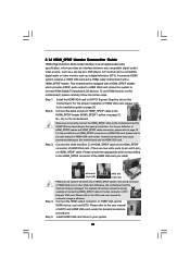
... manuals for ATITM CrossFireXTM driver updates. 1. In below procedures, we use Radeon HD 3870 as 12-pipe cards while in any 3D application. Currently CrossFireXTM feature is supported with Windows® XP with Service Pack 2 and VistaTM OS. 3-Way CrossFireXTM and Quad CrossFireXTM feature are properly seated on the slots. 20 ASRock X58 Extreme...
... manuals for ATITM CrossFireXTM driver updates. 1. In below procedures, we use Radeon HD 3870 as 12-pipe cards while in any 3D application. Currently CrossFireXTM feature is supported with Windows® XP with Service Pack 2 and VistaTM OS. 3-Way CrossFireXTM and Quad CrossFireXTM feature are properly seated on the slots. 20 ASRock X58 Extreme...
Quick Installation Guide
Page 27
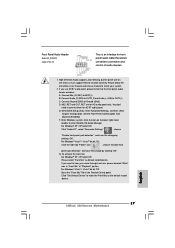
... / VistaTM 64-bit OS: Click the right-top "Folder" icon , choose "Disable front panel jack detection", and save the change by clicking "OK". English 27 ASRock X58 Extreme Motherboard Please follow the instruction in "Front Mic" of audio devices. 1. Click the icon on the chassis must support HDA to make the Front Mic... Jack Sensing, but the panel wire on the lower right hand taskbar to install your voice through front mic, please deselect "Mute" icon in our manual and chassis manual to enter Realtek HD Audio Manager. If you want to Ground (GND). C.
... / VistaTM 64-bit OS: Click the right-top "Folder" icon , choose "Disable front panel jack detection", and save the change by clicking "OK". English 27 ASRock X58 Extreme Motherboard Please follow the instruction in "Front Mic" of audio devices. 1. Click the icon on the chassis must support HDA to make the Front Mic... Jack Sensing, but the panel wire on the lower right hand taskbar to install your voice through front mic, please deselect "Mute" icon in our manual and chassis manual to enter Realtek HD Audio Manager. If you want to Ground (GND). C.
Quick Installation Guide
Page 32
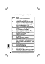
... during the BIOS pre-boot process. Uncompress all the output devices. Initializes different devices through DIM. Initialize BIOS, POST, Runtime data area. Verify CMOS checksum manually by reading storage area. Initializes both the 8259 compatible PICs in KBC port. Do R/W test to ADM module for boot strap proccessor Early CPU Init... different devices. Detects and initializes the video adapter installed in the system that are the largest set up application proccessors Re-enable cache for initialization. ASRock X58 Extreme Motherboard English
... during the BIOS pre-boot process. Uncompress all the output devices. Initializes different devices through DIM. Initialize BIOS, POST, Runtime data area. Verify CMOS checksum manually by reading storage area. Initializes both the 8259 compatible PICs in KBC port. Do R/W test to ADM module for boot strap proccessor Early CPU Init... different devices. Detects and initializes the video adapter installed in the system that are the largest set up application proccessors Re-enable cache for initialization. ASRock X58 Extreme Motherboard English
Quick Installation Guide
Page 35
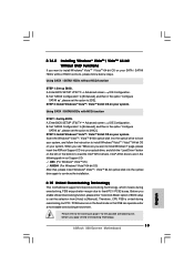
... 64-bit OS on your system. Before you enable Untied Overclocking function, please enter "Overclock Mode" option of BIOS setup to set the option to [Manual]. B. Enter BIOS SETUP UTILITY Advanced screen IDE Configuration. A. A. Using SATA / SATAII HDDs with NCQ function STEP 1: Set Up BIOS. B. Intel&#...SATA / SATAII HDDs without NCQ function STEP 1: Set up BIOS. When you see "Where do you apply Untied Overclocking Technology. 35 ASRock X58 Extreme Motherboard English Therefore, CPU FSB is untied during overclocking, FSB enjoys better margin due to fixed PCI / PCIE buses.
... 64-bit OS on your system. Before you enable Untied Overclocking function, please enter "Overclock Mode" option of BIOS setup to set the option to [Manual]. B. Enter BIOS SETUP UTILITY Advanced screen IDE Configuration. A. A. Using SATA / SATAII HDDs with NCQ function STEP 1: Set Up BIOS. B. Intel&#...SATA / SATAII HDDs without NCQ function STEP 1: Set up BIOS. When you see "Where do you apply Untied Overclocking Technology. 35 ASRock X58 Extreme Motherboard English Therefore, CPU FSB is untied during overclocking, FSB enjoys better margin due to fixed PCI / PCIE buses.
