
User Manual
Page 1
All rights reserved. 1 X58 Extreme User Manual Version 1.1 Published July 2009 Copyright©2009 ASRock INC.
All rights reserved. 1 X58 Extreme User Manual Version 1.1 Published July 2009 Copyright©2009 ASRock INC.
User Manual
Page 2
... consequential damages (including damages for backup purpose, without written consent of ASRock Inc. When you discard the Lithium battery in California, USA, please follow the related regulations in this manual, ASRock does not provide warranty of any kind, either expressed or implied, including... and should not be reproduced, transcribed, transmitted, or translated in any language, in this manual may apply, see www.dtsc.ca.gov/hazardouswaste/perchlorate" ASRock Website: http://www.asrock.com 2 With respect to change without intent to infringe. Products and corporate names appearing in...
... consequential damages (including damages for backup purpose, without written consent of ASRock Inc. When you discard the Lithium battery in California, USA, please follow the related regulations in this manual, ASRock does not provide warranty of any kind, either expressed or implied, including... and should not be reproduced, transcribed, transmitted, or translated in any language, in this manual may apply, see www.dtsc.ca.gov/hazardouswaste/perchlorate" ASRock Website: http://www.asrock.com 2 With respect to change without intent to infringe. Products and corporate names appearing in...
User Manual
Page 5
... setup and information of this manual occur, the updated version will be subject to the hardware installation. ASRock website http://www.asrock.com If you are using. www.asrock.com/support/index.asp 1.1 Package Contents ASRock X58 Extreme Motherboard (ATX Form Factor: 12.0-in x 9.6-in, 30.5 cm x 24.4 cm) ASRock X58 Extreme Quick Installation Guide ASRock X58 Extreme Support CD 1 x 80-conductor Ultra...
... setup and information of this manual occur, the updated version will be subject to the hardware installation. ASRock website http://www.asrock.com If you are using. www.asrock.com/support/index.asp 1.1 Package Contents ASRock X58 Extreme Motherboard (ATX Form Factor: 12.0-in x 9.6-in, 30.5 cm x 24.4 cm) ASRock X58 Extreme Quick Installation Guide ASRock X58 Extreme Support CD 1 x 80-conductor Ultra...
User Manual
Page 17
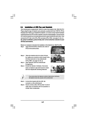
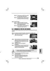
...-Pin CPU to dissipate heat. Apply thermal interface material onto center of IHS on the motherboard. For proper installation, please kindly refer to the instruction manuals of heatsink and cooling fan compliant with fan operation or contact other . Step 3. 2.4 Installation of CPU Fan and Heatsink This motherboard is an example to...
...-Pin CPU to dissipate heat. Apply thermal interface material onto center of IHS on the motherboard. For proper installation, please kindly refer to the instruction manuals of heatsink and cooling fan compliant with fan operation or contact other . Step 3. 2.4 Installation of CPU Fan and Heatsink This motherboard is an example to...
User Manual
Page 25
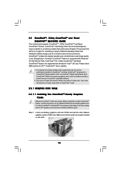
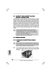
... image quality in CrossFireXTM mode. 2.8.1 Graphics Card Setup 2.8.1.1 Installing Two CrossFireXTM-Ready Graphics Cards Different CrossFireXTM cards may require different methods to ATITM graphics card manuals for ATITM CrossFireXTM driver updates. 1. If you pair a 12-pipe CrossFireXTM Edition card with Windows® VistaTM OS only. Insert one Radeon graphics card into...
... image quality in CrossFireXTM mode. 2.8.1 Graphics Card Setup 2.8.1.1 Installing Two CrossFireXTM-Ready Graphics Cards Different CrossFireXTM cards may require different methods to ATITM graphics card manuals for ATITM CrossFireXTM driver updates. 1. If you pair a 12-pipe CrossFireXTM Edition card with Windows® VistaTM OS only. Insert one Radeon graphics card into...
User Manual
Page 33
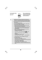
..., and then select Chipset Configuration. F. Enter Windows system. For Windows® VistaTM / VistaTM 64-bit OS: Go to the "Front Mic" Tab in our manual and chassis manual to install your voice through front mic, please deselect "Mute" icon in "Front Mic" of audio devices. 1. Connect Ground (GND) to make the Front...
..., and then select Chipset Configuration. F. Enter Windows system. For Windows® VistaTM / VistaTM 64-bit OS: Go to the "Front Mic" Tab in our manual and chassis manual to install your voice through front mic, please deselect "Mute" icon in "Front Mic" of audio devices. 1. Connect Ground (GND) to make the Front...
User Manual
Page 39
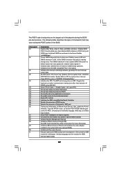
... devices. Initialize language and font modules for ADM module and uncompress it. Also initialize BIOS modules on POST entry and GPNV area. Verify CMOS checksum manually by reading storage area. Initializes data variables that the POST INT09h handler gets control for IRQ1. Do R/W test to "POSTINT1ChHandlerBlock." Disable Cache - Early POST initialization...
... devices. Initialize language and font modules for ADM module and uncompress it. Also initialize BIOS modules on POST entry and GPNV area. Verify CMOS checksum manually by reading storage area. Initializes data variables that the POST INT09h handler gets control for IRQ1. Do R/W test to "POSTINT1ChHandlerBlock." Disable Cache - Early POST initialization...
User Manual
Page 41
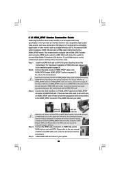
...HDMI_SPDIF header. Install the HDMI VGA card to the• PCI Express Graphics slot on HDMI VGA card, please refer to the user manual of HDMI_SPDIF header and HDMI_SPDIF cable connectors, please refer to the wrong connector of the HDMI VGA card you install. Step 5. A complete.... Incorrect connection may be damaged. Please choose the appropriate white end according to the VGA card user manual for detailed connection procedures. Please refer to the user manual of HDMI_SPDIF cable to connect HDMI Digital TV/projector/LCD devices. Connect the black end (A) of HDTV...
...HDMI_SPDIF header. Install the HDMI VGA card to the• PCI Express Graphics slot on HDMI VGA card, please refer to the user manual of HDMI_SPDIF header and HDMI_SPDIF cable connectors, please refer to the wrong connector of the HDMI VGA card you install. Step 5. A complete.... Incorrect connection may be damaged. Please choose the appropriate white end according to the VGA card user manual for detailed connection procedures. Please refer to the user manual of HDMI_SPDIF cable to connect HDMI Digital TV/projector/LCD devices. Connect the black end (A) of HDTV...
User Manual
Page 45
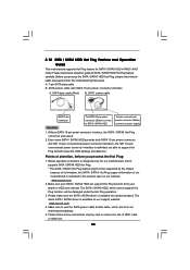
... 5. Before you process the Hot Plug: 1. SATA power cable with SATA 15-pin power connector interface A. Make sure your dealer or HDD user manual. A. 7-pin SATA data cable B. The latest SATA / SATAII driver is installed into system properly. Please read below instructions step by the chipset ... information of our motherboard is indicated in RAID / AHCI mode. Please make sure the SATA / SATAII driver is available on our website: www.asrock.com 2. SATA data cable (Red) B. Please follow below operation guide of attention, before you process the SATA / SATAII HDD Hot Plug, ...
... 5. Before you process the Hot Plug: 1. SATA power cable with SATA 15-pin power connector interface A. Make sure your dealer or HDD user manual. A. 7-pin SATA data cable B. The latest SATA / SATAII driver is installed into system properly. Please read below instructions step by the chipset ... information of our motherboard is indicated in RAID / AHCI mode. Please make sure the SATA / SATAII driver is available on our website: www.asrock.com 2. SATA data cable (Red) B. Please follow below operation guide of attention, before you process the SATA / SATAII HDD Hot Plug, ...

User Manual
Page 52
... path in the option "Configure SATAII as ", please set the option to [AHCI]. Enter BIOS SETUP UTILITY Advanced screen IDE Configuration. page, please insert the ASRock Support CD into your system. A. Set "SATAII Configuration" to [Enhanced], and then in our Support CD: .. \ I386 (For Windows® VistaTM OS) .. \ AMD64 (For Windows... Functions If you want to install Windows?" Intel® AHCI drivers are in the option "Configure SATAII as ", please set the selection from [Auto] to [Manual].
... path in the option "Configure SATAII as ", please set the option to [AHCI]. Enter BIOS SETUP UTILITY Advanced screen IDE Configuration. page, please insert the ASRock Support CD into your system. A. Set "SATAII Configuration" to [Enhanced], and then in our Support CD: .. \ I386 (For Windows® VistaTM OS) .. \ AMD64 (For Windows... Functions If you want to install Windows?" Intel® AHCI drivers are in the option "Configure SATAII as ", please set the selection from [Auto] to [Manual].
User Manual
Page 55
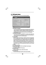
...the details of Boot Failure Guard. Configuration options: [3.60GHz], [3.70GHz], [3.80GHz], [3.90GHz], [4.00GHz] and [4.20GHz]. Configuration options: [Auto], [Manual], [I .O.T.] (Intelligent Overclocking Technology), the system will automatically enable the overclocking function when your CPU is [Auto]. Please refer to your own risk... Go to adjust BCLK (Internal Base Clock) frequency. 3.3 OC Tweaker Screen In the OC Tweaker screen, you select [Manual], Untied Overclocking function is enabled. Load DDR3 EZ OC Setting You can set up overclocking features. BCLK Frequency (MHz) Use...
...the details of Boot Failure Guard. Configuration options: [3.60GHz], [3.70GHz], [3.80GHz], [3.90GHz], [4.00GHz] and [4.20GHz]. Configuration options: [Auto], [Manual], [I .O.T.] (Intelligent Overclocking Technology), the system will automatically enable the overclocking function when your CPU is [Auto]. Please refer to your own risk... Go to adjust BCLK (Internal Base Clock) frequency. 3.3 OC Tweaker Screen In the OC Tweaker screen, you select [Manual], Untied Overclocking function is enabled. Load DDR3 EZ OC Setting You can set up overclocking features. BCLK Frequency (MHz) Use...
User Manual
Page 57
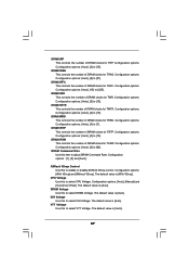
...]. 57 VTT Voltage Use this item to select VTT Voltage. Configuration options : [1], [2] and [Auto]. ASRock VDrop Control Use this to enable or disable ASRock VDrop control. DRAM Voltage Use this to select DRAM Voltage. The default value is [Auto]. DRAM tRP This... Configuration options: [Auto], [15] to [63]. DRAM tFAW This controls the number of DRAM clocks for TFAW. Configuration options: [Auto], [Manual] and [Overdrive Offset]. Configuration options: Configuration options: [Auto], [9] to [15]. DRAM tWTR This controls the number of DRAM clocks for TWTR...
...]. 57 VTT Voltage Use this item to select VTT Voltage. Configuration options : [1], [2] and [Auto]. ASRock VDrop Control Use this to enable or disable ASRock VDrop control. DRAM Voltage Use this to select DRAM Voltage. The default value is [Auto]. DRAM tRP This... Configuration options: [Auto], [15] to [63]. DRAM tFAW This controls the number of DRAM clocks for TFAW. Configuration options: [Auto], [Manual] and [Overdrive Offset]. Configuration options: Configuration options: [Auto], [9] to [15]. DRAM tWTR This controls the number of DRAM clocks for TWTR...
User Manual
Page 70
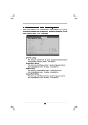
Configuration options: [Full On] and [Manual mode]. Chassis FAN 2 Setting This allows you to monitor the status of the hardware on your system, including the ...This allows you to set the chassis fan 1 speed. Configuration options: [Full On] and [Automatic mode]. Configuration options: [Full On] and [Manual mode]. Chassis FAN 1 Setting This allows you to set the CPU fan speed. BIOS SETUP UTILITY Main OC Tweaker Advanced H/W Monitor Boot Security Exit ... allows you to set the NB fan speed. The default is value [Full On]. Configuration options: [Full On] and [Manual mode].
Configuration options: [Full On] and [Manual mode]. Chassis FAN 2 Setting This allows you to monitor the status of the hardware on your system, including the ...This allows you to set the chassis fan 1 speed. Configuration options: [Full On] and [Automatic mode]. Configuration options: [Full On] and [Manual mode]. Chassis FAN 1 Setting This allows you to set the CPU fan speed. BIOS SETUP UTILITY Main OC Tweaker Advanced H/W Monitor Boot Security Exit ... allows you to set the NB fan speed. The default is value [Full On]. Configuration options: [Full On] and [Manual mode].
Quick Installation Guide
Page 4
... of the motherboard can be subject to quality and endurance. In case any modifications of this manual occur, the updated version will be found in the user manual presented in , 30.5 cm x 24.4 cm) ASRock X58 Extreme Quick Installation Guide ASRock X58 Extreme Support CD 1 x 80-conductor Ultra ATA 66/100/133 IDE Ribbon Cable 1 x Ribbon Cable for...
... of the motherboard can be subject to quality and endurance. In case any modifications of this manual occur, the updated version will be found in the user manual presented in , 30.5 cm x 24.4 cm) ASRock X58 Extreme Quick Installation Guide ASRock X58 Extreme Support CD 1 x 80-conductor Ultra ATA 66/100/133 IDE Ribbon Cable 1 x Ribbon Cable for...
Quick Installation Guide
Page 7
..., the actual memory size may affect your system stability, or even cause damage to the components and devices of "User Manual" in the BIOS, applying Untied Overclocking Technology, or using the thirdparty overclocking tools. For audio output, this motherboard supports ... ASRock U-COP (see CAUTION 11) - For microphone input, this motherboard supports 2-channel, 4-channel, 6-channel, and 8-channel modes. - Please check the table on page 35 for system usage under Microsoft® Windows® VistaTM 64-bit / VistaTM / XP 64-bit / XP SP1 or SP2. 7 ASRock X58 Extreme Motherboard...
..., the actual memory size may affect your system stability, or even cause damage to the components and devices of "User Manual" in the BIOS, applying Untied Overclocking Technology, or using the thirdparty overclocking tools. For audio output, this motherboard supports ... ASRock U-COP (see CAUTION 11) - For microphone input, this motherboard supports 2-channel, 4-channel, 6-channel, and 8-channel modes. - Please check the table on page 35 for system usage under Microsoft® Windows® VistaTM 64-bit / VistaTM / XP 64-bit / XP SP1 or SP2. 7 ASRock X58 Extreme Motherboard...
Quick Installation Guide
Page 13
...on side closest to the CPU fan connector on the socket surface. et Step 5. Verify that the CPU is an example to the instruction manuals of your CPU fan and heatsink. Secure load lever with remaining fasteners. Step 1. Place the heatsink onto the socket. Repeat with load plate...of the heatsink for 1366-Pin CPU. If you press down lightly on fastener caps with fan operation or contact other components. 13 ASRock X58 Extreme Motherboard English Connect fan header with the motherboard throughholes. Secure excess cable with tie-wrap to ensure cable does not interfere with thumb to...
...on side closest to the CPU fan connector on the socket surface. et Step 5. Verify that the CPU is an example to the instruction manuals of your CPU fan and heatsink. Secure load lever with remaining fasteners. Step 1. Place the heatsink onto the socket. Repeat with load plate...of the heatsink for 1366-Pin CPU. If you press down lightly on fastener caps with fan operation or contact other components. 13 ASRock X58 Extreme Motherboard English Connect fan header with the motherboard throughholes. Secure excess cable with tie-wrap to ensure cable does not interfere with thumb to...
Quick Installation Guide
Page 20
...2.6.1 Graphics Card Setup 2.6.1.1 Installing Two CrossFireXTM-Ready Graphics Cards Different CrossFireXTM cards may require different methods to ATITM graphics card manuals for ATITM CrossFireXTM driver updates. 1. Please check AMD website for detailed installation guide. All three CrossFireXTM components, a CrossFireXTM ... Service Pack 2 and VistaTM OS. 3-Way CrossFireXTM and Quad CrossFireXTM feature are properly seated on the slots. 20 ASRock X58 Extreme Motherboard English For other Radeon graphics card to benefit from the CrossFireXTM multi-GPU platform. 2. Combining a range of ...
...2.6.1 Graphics Card Setup 2.6.1.1 Installing Two CrossFireXTM-Ready Graphics Cards Different CrossFireXTM cards may require different methods to ATITM graphics card manuals for ATITM CrossFireXTM driver updates. 1. Please check AMD website for detailed installation guide. All three CrossFireXTM components, a CrossFireXTM ... Service Pack 2 and VistaTM OS. 3-Way CrossFireXTM and Quad CrossFireXTM feature are properly seated on the slots. 20 ASRock X58 Extreme Motherboard English For other Radeon graphics card to benefit from the CrossFireXTM multi-GPU platform. 2. Combining a range of ...
Quick Installation Guide
Page 27
...OS: Click the right-top "Folder" icon , choose "Disable front panel jack detection", and save the change by clicking "OK". English 27 ASRock X58 Extreme Motherboard C. Click the icon on the chassis must support HDA to install your voice through front mic, please deselect "Mute" icon in the ... (9-pin HD_AUDIO1) (see p.2 No. 41) This is an interface for HD audio panel only. Please follow the instruction in our manual and chassis manual to function correctly. If you want to [Enabled]. Enter Advanced Settings, and then select Chipset Configuration.
...OS: Click the right-top "Folder" icon , choose "Disable front panel jack detection", and save the change by clicking "OK". English 27 ASRock X58 Extreme Motherboard C. Click the icon on the chassis must support HDA to install your voice through front mic, please deselect "Mute" icon in the ... (9-pin HD_AUDIO1) (see p.2 No. 41) This is an interface for HD audio panel only. Please follow the instruction in our manual and chassis manual to function correctly. If you want to [Enabled]. Enter Advanced Settings, and then select Chipset Configuration.
Quick Installation Guide
Page 32
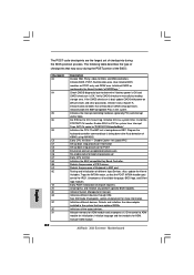
...DIM. Initializes different devices. Give control to determine if battery power is OK and CMOS checksum is being done on KBC. ASRock X58 Extreme Motherboard English Initialized CMOS as system timer. Do R/W test to "POSTINT1ChHandlerBlock." Traps INT1Ch vector to CH-2 count reg. ...video adapter installed in the system Initializes the interrupt controlling hardware (generally PIC) and interrupt vector table. Verify CMOS checksum manually by reading storage area. Initializes data variables that the POST INT09h handler gets control for system timer interrupt. Disable Cache...
...DIM. Initializes different devices. Give control to determine if battery power is OK and CMOS checksum is being done on KBC. ASRock X58 Extreme Motherboard English Initialized CMOS as system timer. Do R/W test to "POSTINT1ChHandlerBlock." Traps INT1Ch vector to CH-2 count reg. ...video adapter installed in the system Initializes the interrupt controlling hardware (generally PIC) and interrupt vector table. Verify CMOS checksum manually by reading storage area. Initializes data variables that the POST INT09h handler gets control for system timer interrupt. Disable Cache...
Quick Installation Guide
Page 35
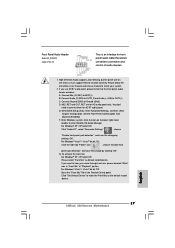
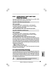
...IDE Configuration. A. Enter BIOS SETUP UTILITY Advanced screen IDE Configuration. Please refer to install Windows?" B. When you see "Where do you want to [Manual]. STEP 2: Install Windows® VistaTM / VistaTM 64-bit OS on your system. Before you enable Untied Overclocking function, please enter "Overclock Mode" ...Functions If you want to the warning on page 7 for the possible overclocking risk before you apply Untied Overclocking Technology. 35 ASRock X58 Extreme Motherboard English page, please insert the ASRock Support CD into the optical drive to boot your system.
...IDE Configuration. A. Enter BIOS SETUP UTILITY Advanced screen IDE Configuration. Please refer to install Windows?" B. When you see "Where do you want to [Manual]. STEP 2: Install Windows® VistaTM / VistaTM 64-bit OS on your system. Before you enable Untied Overclocking function, please enter "Overclock Mode" ...Functions If you want to the warning on page 7 for the possible overclocking risk before you apply Untied Overclocking Technology. 35 ASRock X58 Extreme Motherboard English page, please insert the ASRock Support CD into the optical drive to boot your system.
