
User Manual
Page 3
... 1 1.1 Package Contents 1 1.2 Specifications 2 1.3 Motherboard Layout 5 1.4 I/O Panel 7 Chapter 2 Installation 9 2.1 Installing Memory Modules (SO-DIMM) 10 2.2 Expansion Slots (PCI Express Slots) 12 2.3 Jumpers Setup 13 2.4 Onboard Headers and Connectors 14 Chapter 3 Software and Utilities Operation 18 3.1 Installing Drivers 18 3.2 A-Tuning 19 3.3 Intel® Smart Connect Technology 21 3.4 ASRock Cloud 26 3.5 ASRock APP Shop 36 3.5.1 UI Overview 36 3.5.2 Apps 37 3.5.3 BIOS & Drivers 40 3.5.4 Setting 41 3.6 Start8 42 Chapter 4 UEFI SETUP UTILITY 45
... 1 1.1 Package Contents 1 1.2 Specifications 2 1.3 Motherboard Layout 5 1.4 I/O Panel 7 Chapter 2 Installation 9 2.1 Installing Memory Modules (SO-DIMM) 10 2.2 Expansion Slots (PCI Express Slots) 12 2.3 Jumpers Setup 13 2.4 Onboard Headers and Connectors 14 Chapter 3 Software and Utilities Operation 18 3.1 Installing Drivers 18 3.2 A-Tuning 19 3.3 Intel® Smart Connect Technology 21 3.4 ASRock Cloud 26 3.5 ASRock APP Shop 36 3.5.1 UI Overview 36 3.5.2 Apps 37 3.5.3 BIOS & Drivers 40 3.5.4 Setting 41 3.6 Start8 42 Chapter 4 UEFI SETUP UTILITY 45

User Manual
Page 5
... conforming to ASRock's commitment to change without further notice. Chapter 4 contains the configuration guide of the software and utilities. Because the motherboard specifications and the BIOS software might be updated, the content of this manual, Chapter 1 and 2 contains the introduction of this motherboard, please visit our website for purchasing ASRock Q2900-ITX motherboard, a reliable motherboard produced under ASRock's consistently stringent quality control. You may find the latest VGA cards and CPU support list on ASRock's website...
... conforming to ASRock's commitment to change without further notice. Chapter 4 contains the configuration guide of the software and utilities. Because the motherboard specifications and the BIOS software might be updated, the content of this manual, Chapter 1 and 2 contains the introduction of this motherboard, please visit our website for purchasing ASRock Q2900-ITX motherboard, a reliable motherboard produced under ASRock's consistently stringent quality control. You may find the latest VGA cards and CPU support list on ASRock's website...
User Manual
Page 6
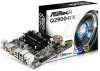
... HDMI Ports English Audio • 7.1 CH HD Audio with max. 1.2 Specifications Platform • Mini-ITX Form Factor • All Solid Capacitor design • High Density Glass Fabric PCB CPU • Intel® Quad-Core Pentium® Processor J2900 (2.41 GHz) Memory • Dual Channel DDR3/DDR3L Memory Technology • 2 x DDR3/DDR3L SO-DIMM Slots • Supports DDR3/DDR3L 1333/1066 non-ECC, un-buffered memory • Max. Expansion Slot • 1 x PCI Express 2.0 x1 Slot...
... HDMI Ports English Audio • 7.1 CH HD Audio with max. 1.2 Specifications Platform • Mini-ITX Form Factor • All Solid Capacitor design • High Density Glass Fabric PCB CPU • Intel® Quad-Core Pentium® Processor J2900 (2.41 GHz) Memory • Dual Channel DDR3/DDR3L Memory Technology • 2 x DDR3/DDR3L SO-DIMM Slots • Supports DDR3/DDR3L 1333/1066 non-ECC, un-buffered memory • Max. Expansion Slot • 1 x PCI Express 2.0 x1 Slot...

User Manual
Page 7
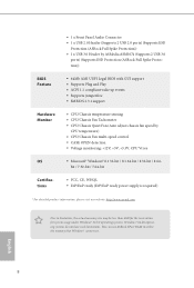
... (ASRock Full Spike Protection)) • 1 x RJ-45 LAN Port with LED (ACT/LINK LED and SPEED LED) • HD Audio Jacks: Rear Speaker / Central / Bass / Line in / Front Speaker / Microphone Storage • 2 x SATA2 3.0 Gb/s Connectors, support NCQ, AHCI and Hot Plug • 2 x SATA3 6.0 Gb/s Connectors by ASMedia ASM1061, support NCQ, AHCI and Hot Plug Connector • 1 x Print Port Header • 1 x COM Port Header • 1 x TPM Header • 1 x Chassis Intrusion Header • 1 x CPU Fan Connector (3-pin) • 1 x Chassis Fan Connector (3-pin) • 1 x 24 pin ATX Power...
... (ASRock Full Spike Protection)) • 1 x RJ-45 LAN Port with LED (ACT/LINK LED and SPEED LED) • HD Audio Jacks: Rear Speaker / Central / Bass / Line in / Front Speaker / Microphone Storage • 2 x SATA2 3.0 Gb/s Connectors, support NCQ, AHCI and Hot Plug • 2 x SATA3 6.0 Gb/s Connectors by ASMedia ASM1061, support NCQ, AHCI and Hot Plug Connector • 1 x Print Port Header • 1 x COM Port Header • 1 x TPM Header • 1 x Chassis Intrusion Header • 1 x CPU Fan Connector (3-pin) • 1 x Chassis Fan Connector (3-pin) • 1 x 24 pin ATX Power...

User Manual
Page 8
... 2 USB 3.0 ports) (Supports ESD Protection (ASRock Full Spike Protection)) • 64Mb AMI UEFI Legal BIOS with GUI support • Supports Plug and Play • ACPI 1.1 compliant wake up events • Supports jumperfree • SMBIOS 2.3.1 support • CPU/Chassis temperature sensing • CPU/Chassis Fan Tachometer • CPU/Chassis Quiet Fan (Auto adjust chassis fan speed by CPU temperature) • CPU/Chassis Fan multi-speed control • CASE OPEN detection • Voltage monitoring: +12V, +5V, +3.3V, CPU Vcore • Microsoft® Windows® 8.1 32-bit / 8.1 64-bit...
... 2 USB 3.0 ports) (Supports ESD Protection (ASRock Full Spike Protection)) • 64Mb AMI UEFI Legal BIOS with GUI support • Supports Plug and Play • ACPI 1.1 compliant wake up events • Supports jumperfree • SMBIOS 2.3.1 support • CPU/Chassis temperature sensing • CPU/Chassis Fan Tachometer • CPU/Chassis Quiet Fan (Auto adjust chassis fan speed by CPU temperature) • CPU/Chassis Fan multi-speed control • CASE OPEN detection • Voltage monitoring: +12V, +5V, +3.3V, CPU Vcore • Microsoft® Windows® 8.1 32-bit / 8.1 64-bit...

User Manual
Page 9
1.3 Motherboard Layout 64Mb BIOS CPU_FAN1 DDR3_A1 Q2900-ITX PS2 Mouse PS2 Keyboard RoHS Q2900-ITX DVI1 VGA1 AT X P W R 1 DDR3_B1 Front USB 3.0 USB 2.0 T: USB3 B: USB4 CMOS Battery MINI_PCIE1 USB 3.0 T: USB3 Top: RJ-45 LAN B: USB4 HD_AUDIO1 1 Super I/O Top: CTR BASS Center: REAR SPK FRONT Top: LINE IN Center: AUDIO CODEC LPT1 1 PCIE1 USB1_2 1 SATA3_A2 SATA3_A1 SATA2_2 SATA2_1 COM1 1 TPMS1 1 CLRCMOS1 CI1 1 1 SPEAKER1 1 USB3_1_2 PANEL1 PLED PWRBTN 1 HDLED RESET Bottom: MIC IN HDMI Bottom: Optical SPDIF English 5
1.3 Motherboard Layout 64Mb BIOS CPU_FAN1 DDR3_A1 Q2900-ITX PS2 Mouse PS2 Keyboard RoHS Q2900-ITX DVI1 VGA1 AT X P W R 1 DDR3_B1 Front USB 3.0 USB 2.0 T: USB3 B: USB4 CMOS Battery MINI_PCIE1 USB 3.0 T: USB3 Top: RJ-45 LAN B: USB4 HD_AUDIO1 1 Super I/O Top: CTR BASS Center: REAR SPK FRONT Top: LINE IN Center: AUDIO CODEC LPT1 1 PCIE1 USB1_2 1 SATA3_A2 SATA3_A1 SATA2_2 SATA2_1 COM1 1 TPMS1 1 CLRCMOS1 CI1 1 1 SPEAKER1 1 USB3_1_2 PANEL1 PLED PWRBTN 1 HDLED RESET Bottom: MIC IN HDMI Bottom: Optical SPDIF English 5
User Manual
Page 13
... to use a grounded wrist strap or touch a safety grounded object before installing or removing the motherboard. Failure to unplug the power cord before you handle the components. • Hold components by the edges and do not touch the ICs. • Whenever you install motherboard components or change any components, place them on a carpet. Q2900-ITX Chapter 2 Installation This is a Mini-ITX form factor motherboard.
... to use a grounded wrist strap or touch a safety grounded object before installing or removing the motherboard. Failure to unplug the power cord before you handle the components. • Hold components by the edges and do not touch the ICs. • Whenever you install motherboard components or change any components, place them on a carpet. Q2900-ITX Chapter 2 Installation This is a Mini-ITX form factor motherboard.

User Manual
Page 17
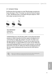
... power cord from the power supply. When the jumper cap is placed on these 2 pins. English 13 The illustration shows a 3-pin jumper whose pin1 and pin2 are setup. Clear CMOS Jumper (CLRCMOS1) (see p.5, No. 13) Default Clear CMOS CLRCMOS1 allows you need to clear the record of previous chassis intrusion status. Q2900-ITX 2.3 Jumpers Setup The illustration shows how jumpers are "Short" when a jumper cap is placed on the pins, the jumper is "Short". To clear and reset...
... power cord from the power supply. When the jumper cap is placed on these 2 pins. English 13 The illustration shows a 3-pin jumper whose pin1 and pin2 are setup. Clear CMOS Jumper (CLRCMOS1) (see p.5, No. 13) Default Clear CMOS CLRCMOS1 allows you need to clear the record of previous chassis intrusion status. Q2900-ITX 2.3 Jumpers Setup The illustration shows how jumpers are "Short" when a jumper cap is placed on the pins, the jumper is "Short". To clear and reset...
User Manual
Page 20
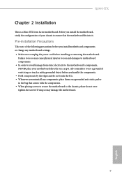
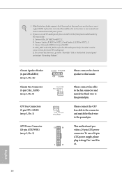
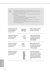
... 1. High Definition Audio supports Jack Sensing, but the panel wire on the chassis must support HDA to this header. Chassis Speaker Header (4-pin SPEAKER1) (see p.5, No. 11) Chassis Fan Connector (3-pin CHA_FAN1) (see p.5, No. 8) DUMMY SPEAKER 1 +5V DUMMY FAN_SPEED FAN_VOLTAGE GND CPU Fan Connectors (3-pin CPU_FAN1) (see p.5, No. 1) GND FAN_VOLTAGE FAN_SPEED ATX Power Connector (24-pin ATXPWR1) (see p.5, No. 3) 12 24 1 13 Please connect the chassis speaker to function correctly. To use an AC'97 audio panel, please install it along Pin 1 and Pin...
... 1. High Definition Audio supports Jack Sensing, but the panel wire on the chassis must support HDA to this header. Chassis Speaker Header (4-pin SPEAKER1) (see p.5, No. 11) Chassis Fan Connector (3-pin CHA_FAN1) (see p.5, No. 8) DUMMY SPEAKER 1 +5V DUMMY FAN_SPEED FAN_VOLTAGE GND CPU Fan Connectors (3-pin CPU_FAN1) (see p.5, No. 1) GND FAN_VOLTAGE FAN_SPEED ATX Power Connector (24-pin ATXPWR1) (see p.5, No. 3) 12 24 1 13 Please connect the chassis speaker to function correctly. To use an AC'97 audio panel, please install it along Pin 1 and Pin...

User Manual
Page 22
... Support CD that comes with the motherboard contains necessary drivers and useful utilities that the motherboard supports. Click on the file "ASRSETUP.EXE" in your system will be auto-detected and listed on the support CD driver page. Drivers Menu The drivers compatible to display the menu. To improve Windows 7 compatibility, please download and install the following hot fix provided by Microsoft. If the Main Menu does not appear automatically, locate and double click on a specific...
... Support CD that comes with the motherboard contains necessary drivers and useful utilities that the motherboard supports. Click on the file "ASRSETUP.EXE" in your system will be auto-detected and listed on the support CD driver page. Drivers Menu The drivers compatible to display the menu. To improve Windows 7 compatibility, please download and install the following hot fix provided by Microsoft. If the Main Menu does not appear automatically, locate and double click on a specific...

User Manual
Page 25
... Start and change the value from Windows® sleep state to refresh email or social networking applications. Q2900-ITX 3.3 Intel® Smart Connect Technology Intel® Smart Connect Technology is not in Windows Registry Editor. It saves your waiting time and keeps the content always up-to crash while booting. or 64-bit edition) • Set the SATA mode to avoid loss. 1. If Windows 8/7 is already installed under IDE mode, directly changing the SATA mode to AHCI...
... Start and change the value from Windows® sleep state to refresh email or social networking applications. Q2900-ITX 3.3 Intel® Smart Connect Technology Intel® Smart Connect Technology is not in Windows Registry Editor. It saves your waiting time and keeps the content always up-to crash while booting. or 64-bit edition) • Set the SATA mode to avoid loss. 1. If Windows 8/7 is already installed under IDE mode, directly changing the SATA mode to AHCI...

User Manual
Page 49
... pressing the reset button on the computer, otherwise, the Power-On-Self-Test (POST) will continue with the following selections: Main For setting system time/date information Advanced For advanced system configurations Tool Useful tools H/W Monitor Displays current hardware status Security For security settings Boot For configuring boot settings and boot priority Exit Exit the current screen or the UEFI Setup Utility English 45 If you wish to configure your screen. 4.1.1 UEFI Menu Bar...
... pressing the reset button on the computer, otherwise, the Power-On-Self-Test (POST) will continue with the following selections: Main For setting system time/date information Advanced For advanced system configurations Tool Useful tools H/W Monitor Displays current hardware status Security For security settings Boot For configuring boot settings and boot priority Exit Exit the current screen or the UEFI Setup Utility English 45 If you wish to configure your screen. 4.1.1 UEFI Menu Bar...

User Manual
Page 56
Onboard LAN Enable or disable the onboard network interface controller. Restore on . If [Power On] is shut down. PCIE1 Link Speed Select the link speed for power saving when the computer is selected, the system will remain off the Power and LAN LEDs when the system enters into Standby/Hibernation mode. 52 English Good Night LED By enabling Good Night LED, the Power/LAN LEDs will also automatically switch off when the power recovers. Deep...
Onboard LAN Enable or disable the onboard network interface controller. Restore on . If [Power On] is shut down. PCIE1 Link Speed Select the link speed for power saving when the computer is selected, the system will remain off the Power and LAN LEDs when the system enters into Standby/Hibernation mode. 52 English Good Night LED By enabling Good Night LED, the Power/LAN LEDs will also automatically switch off when the power recovers. Deep...

User Manual
Page 63
Select UEFI Setup Only to disable legacy USB support. 4.3.7 USB Configuration Q2900-ITX USB Controller Enable or disable all the USB 3.0 ports. If you encounter USB compatibility issues it is recommended to support USB devices under the UEFI setup and Windows/Linux operating systems only. 59 English USB 3.0 Controller Enable or disable all the USB ports. Legacy USB Support Enable or disable Legacy OS Support for USB 2.0 devices.
Select UEFI Setup Only to disable legacy USB support. 4.3.7 USB Configuration Q2900-ITX USB Controller Enable or disable all the USB 3.0 ports. If you encounter USB compatibility issues it is recommended to support USB devices under the UEFI setup and Windows/Linux operating systems only. 59 English USB 3.0 Controller Enable or disable all the USB ports. Legacy USB Support Enable or disable Legacy OS Support for USB 2.0 devices.

User Manual
Page 65
Please setup network configuration before using Internet Flash. *For BIOS backup and recovery purpose, it is recommended to plug in your UEFI. 4.4 Tools Q2900-ITX Instant Flash Save UEFI files in your USB storage device and run Instant Flash to update your USB pen drive before using this function. 61 English Internet Flash ASRock Internet Flash downloads and updates the latest UEFI firmware version from our servers for you.
Please setup network configuration before using Internet Flash. *For BIOS backup and recovery purpose, it is recommended to plug in your UEFI. 4.4 Tools Q2900-ITX Instant Flash Save UEFI files in your USB storage device and run Instant Flash to update your USB pen drive before using this function. 61 English Internet Flash ASRock Internet Flash downloads and updates the latest UEFI firmware version from our servers for you.

User Manual
Page 66
Internet Setting Enable or disable sound effects in the setup utility. UEFI Download Server Select a server to configure internet connection settings for Internet Flash. Network Configuration Use this to download the UEFI firmware. 62 English
Internet Setting Enable or disable sound effects in the setup utility. UEFI Download Server Select a server to configure internet connection settings for Internet Flash. Network Configuration Use this to download the UEFI firmware. 62 English

User Manual
Page 67
Q2900-ITX 4.5 Hardware Health Event Monitoring Screen This section allows you to set CPU fan 1's speed. Configuration options: [Full On] and [Automatic Mode]. Chassis Fan 1 Setting This allows you to monitor the status of the hardware on your system, including the parameters of the CPU temperature, motherboard temperature, fan speed and voltage. Case Open Feature Enable or disable Case Open Feature to set chassis fan 1's speed. The default value is [Full On]. The default value is [Full On]. Configuration options: [Full On], [Automatic Mode] and [Manual]. CPU Fan 1 Setting ...
Q2900-ITX 4.5 Hardware Health Event Monitoring Screen This section allows you to set CPU fan 1's speed. Configuration options: [Full On] and [Automatic Mode]. Chassis Fan 1 Setting This allows you to monitor the status of the hardware on your system, including the parameters of the CPU temperature, motherboard temperature, fan speed and voltage. Case Open Feature Enable or disable Case Open Feature to set chassis fan 1's speed. The default value is [Full On]. The default value is [Full On]. Configuration options: [Full On], [Automatic Mode] and [Manual]. CPU Fan 1 Setting ...
Quick Installation Guide
Page 10
... 2 USB 3.0 ports) (Supports ESD Protection (ASRock Full Spike Protection)) • 64Mb AMI UEFI Legal BIOS with GUI support • Supports Plug and Play • ACPI 1.1 compliant wake up events • Supports jumperfree • SMBIOS 2.3.1 support • CPU/Chassis temperature sensing • CPU/Chassis Fan Tachometer • CPU/Chassis Quiet Fan (Auto adjust chassis fan speed by CPU temperature) • CPU/Chassis Fan multi-speed control • CASE OPEN detection • Voltage monitoring: +12V, +5V, +3.3V, CPU Vcore • Microsot® Windows® 8.1 32-bit / 8.1 64-bit...
... 2 USB 3.0 ports) (Supports ESD Protection (ASRock Full Spike Protection)) • 64Mb AMI UEFI Legal BIOS with GUI support • Supports Plug and Play • ACPI 1.1 compliant wake up events • Supports jumperfree • SMBIOS 2.3.1 support • CPU/Chassis temperature sensing • CPU/Chassis Fan Tachometer • CPU/Chassis Quiet Fan (Auto adjust chassis fan speed by CPU temperature) • CPU/Chassis Fan multi-speed control • CASE OPEN detection • Voltage monitoring: +12V, +5V, +3.3V, CPU Vcore • Microsot® Windows® 8.1 32-bit / 8.1 64-bit...
Quick Installation Guide
Page 15
... case open may be cleared only if the CMOS battery is "Short". Please be noted that the password, date, time, and user default proile will be detected. Ater waiting for 5 seconds. If you need to default setup, please turn of previous chassis intrusion status. If you do not clear the CMOS right ater you to short pin2 and pin3 on these 2 pins. he illustration shows how jumpers...
... case open may be cleared only if the CMOS battery is "Short". Please be noted that the password, date, time, and user default proile will be detected. Ater waiting for 5 seconds. If you need to default setup, please turn of previous chassis intrusion status. If you do not clear the CMOS right ater you to short pin2 and pin3 on these 2 pins. he illustration shows how jumpers...
Quick Installation Guide
Page 18
... the panel wire on the chassis must support HDA to the ground pin. If you use a 20-pin ATX power supply, please plug it to the front panel audio header by the steps below: A. To use an AC'97 audio panel, please install it along Pin 1 and Pin 13. his motherboard provides a 24-pin ATX power connector. Chassis Speaker Header (4-pin SPEAKER1) (see p.1, No. 11) Chassis Fan Connector (3-pin CHA_FAN1) (see p.1, No. 8) DUMMY SPEAKER 1 +5V DUMMY FAN_SPEED FAN_VOLTAGE GND CPU Fan Connectors (3-pin CPU_FAN1) (see p.1, No. 1) ATX Power Connector (24-pin ATXPWR1...
... the panel wire on the chassis must support HDA to the ground pin. If you use a 20-pin ATX power supply, please plug it to the front panel audio header by the steps below: A. To use an AC'97 audio panel, please install it along Pin 1 and Pin 13. his motherboard provides a 24-pin ATX power connector. Chassis Speaker Header (4-pin SPEAKER1) (see p.1, No. 11) Chassis Fan Connector (3-pin CHA_FAN1) (see p.1, No. 8) DUMMY SPEAKER 1 +5V DUMMY FAN_SPEED FAN_VOLTAGE GND CPU Fan Connectors (3-pin CPU_FAN1) (see p.1, No. 1) ATX Power Connector (24-pin ATXPWR1...


