User Manual
Page 3
... of Memory Modules (DIMM 12 2.4 Expansion Slots (PCI, AMR, and AGP Slots 13 2.5 Jumpers Setup 14 2.6 Onboard Headers and Connectors 15 2.7 Serial ATA (SATA) Hard Disks Installation 18 2.8 Hot Plug and Hot Swap Functions for SATA HDDs ....... 18 2.9 Installing Windows 2000 / Windows XP With RAID Functions 19 2.10 Installing Windows 98 / ME / 2000 / XP Without RAID Functions 20 3. BIOS SETUP UTILITY 21 3.1 Introduction 21 3.1.1 BIOS Menu Bar 21 3.1.2 Navigation Keys 22 3.2 Main Screen 22 3.3 Advanced Screen 22 3.3.1 CPU Configuration 23 3.3.2 Chipset Configuration 24 3.3.3 ACPI...
... of Memory Modules (DIMM 12 2.4 Expansion Slots (PCI, AMR, and AGP Slots 13 2.5 Jumpers Setup 14 2.6 Onboard Headers and Connectors 15 2.7 Serial ATA (SATA) Hard Disks Installation 18 2.8 Hot Plug and Hot Swap Functions for SATA HDDs ....... 18 2.9 Installing Windows 2000 / Windows XP With RAID Functions 19 2.10 Installing Windows 98 / ME / 2000 / XP Without RAID Functions 20 3. BIOS SETUP UTILITY 21 3.1 Introduction 21 3.1.1 BIOS Menu Bar 21 3.1.2 Navigation Keys 22 3.2 Main Screen 22 3.3 Advanced Screen 22 3.3.1 CPU Configuration 23 3.3.2 Chipset Configuration 24 3.3.3 ACPI...
User Manual
Page 5
... conforming to ASRock's commitment to the hardware installation. Chapter 3 and 4 contain the configuration guide to BIOS setup and information of the motherboard and step-bystep guide to quality and endurance. ASRock website http://www.asrock.com 1.1 Package Contents ASRock P4VM8 Motherboard (Micro ATX Form Factor: 9.6-in x 8.0-in Floppy Drive One Serial ATA (SATA) Cable One Serial ATA (SATA) HDD Power Cable(Optional) One ASRock I/O PlusTM Shield One COM Port Bracket 5 Because the motherboard specifications and the BIOS software might be updated, the...
... conforming to ASRock's commitment to the hardware installation. Chapter 3 and 4 contain the configuration guide to BIOS setup and information of the motherboard and step-bystep guide to quality and endurance. ASRock website http://www.asrock.com 1.1 Package Contents ASRock P4VM8 Motherboard (Micro ATX Form Factor: 9.6-in x 8.0-in Floppy Drive One Serial ATA (SATA) Cable One Serial ATA (SATA) HDD Power Cable(Optional) One ASRock I/O PlusTM Shield One COM Port Bracket 5 Because the motherboard specifications and the BIOS software might be updated, the...

User Manual
Page 6
... Mode 6 Supports up to 4 IDE devices Serial ATA: 2 SATA connectors Support up to 1.5Gb/s data transfer rate Floppy Port: Supports up to 2 floppy disk drives Audio: 5.1 channels AC'97 Audio OnBoard VGA: S3 UnichronR PRO, supports DX7 H / W LAN: Speed: 802.3u (10/100 Ethernet), supports Wake-On-LAN Hardware Monitor: CPU temperature sensing Chassis temperature sensing CPU overheat shutdown to protect CPU life (ASRock U-COP)(see CAUTION 2) CPU fan tachometer Chassis fan tachometer Voltage monitoring: +12V, +5V, +3.3V, Vcore PCI slots: 3 slots with PCI Specification 2.2, PCI3...
... Mode 6 Supports up to 4 IDE devices Serial ATA: 2 SATA connectors Support up to 1.5Gb/s data transfer rate Floppy Port: Supports up to 2 floppy disk drives Audio: 5.1 channels AC'97 Audio OnBoard VGA: S3 UnichronR PRO, supports DX7 H / W LAN: Speed: 802.3u (10/100 Ethernet), supports Wake-On-LAN Hardware Monitor: CPU temperature sensing Chassis temperature sensing CPU overheat shutdown to protect CPU life (ASRock U-COP)(see CAUTION 2) CPU fan tachometer Chassis fan tachometer Voltage monitoring: +12V, +5V, +3.3V, Vcore PCI slots: 3 slots with PCI Specification 2.2, PCI3...
User Manual
Page 7
.../2 keyboard port, 1 VGA port, 1 parallel port: ECP/EPP support, 6 ready-to perform over-clocking. Before you install the PC system. 3. Do NOT use USB 2.0 ports, 1 RJ 45 port, Audio Jack: Line In / Line Out / Microphone BIOS: AMI BIOS Supports "Plug and Play" ACPI 1.1 compliance wake up events Supports jumperfree SMBIOS 2.3.1 support CPU frequency stepless control (only for USB 2.0 works fine under Microsoft® Windows® 98 / ME. 5. While CPU overheat is not recommended to -use a 3.3V AGP card on the motherboard...
.../2 keyboard port, 1 VGA port, 1 parallel port: ECP/EPP support, 6 ready-to perform over-clocking. Before you install the PC system. 3. Do NOT use USB 2.0 ports, 1 RJ 45 port, Audio Jack: Line In / Line Out / Microphone BIOS: AMI BIOS Supports "Plug and Play" ACPI 1.1 compliance wake up events Supports jumperfree SMBIOS 2.3.1 support CPU frequency stepless control (only for USB 2.0 works fine under Microsoft® Windows® 98 / ME. 5. While CPU overheat is not recommended to -use a 3.3V AGP card on the motherboard...
User Manual
Page 8
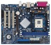
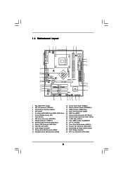
... Chassis Speaker Header (SPEAKER 1) 18 USB 2.0 Header (USB67, Blue) 19 Serial Port Connector (COM1) 20 AMR Slot (AMR1) 21 Internal Audio Connector: CD1 (Black) 22 Internal Audio Connector: AUX1 (White) 23 3 x PCI Slots (PCI1- 3) 24 Clear CMOS Jumper (CLRCMOS1) 25 JR1 / JL1 Jumpers 26 Front Panel Audio Header (AUDIO1) 27 Chassis Fan Connector (CHA_FAN1) 28 Shared USB 2.0 Header (USB4_5, Blue) 29 North Bridge Controller 30 CPU Fan Connector (CPU_FAN1) 8 1.3 Motherboard Layout PS2 Keyboard 1 23 4 20.3cm (8.0 in) PS2 Mouse 1 PS2_USB_PWR1 ATX12V1 56 1 IR1 Super I/O 4Mb BIOS PARALLEL...
... Chassis Speaker Header (SPEAKER 1) 18 USB 2.0 Header (USB67, Blue) 19 Serial Port Connector (COM1) 20 AMR Slot (AMR1) 21 Internal Audio Connector: CD1 (Black) 22 Internal Audio Connector: AUX1 (White) 23 3 x PCI Slots (PCI1- 3) 24 Clear CMOS Jumper (CLRCMOS1) 25 JR1 / JL1 Jumpers 26 Front Panel Audio Header (AUDIO1) 27 Chassis Fan Connector (CHA_FAN1) 28 Shared USB 2.0 Header (USB4_5, Blue) 29 North Bridge Controller 30 CPU Fan Connector (CPU_FAN1) 8 1.3 Motherboard Layout PS2 Keyboard 1 23 4 20.3cm (8.0 in) PS2 Mouse 1 PS2_USB_PWR1 ATX12V1 56 1 IR1 Super I/O 4Mb BIOS PARALLEL...
User Manual
Page 16
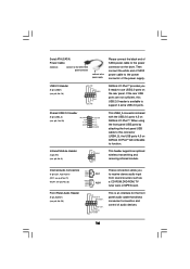
... the USB ports 4,5 on the drive. R MIC-POWER MIC This is available to support 2 extra USB 2.0 ports. O U T- L GND A U D - Then connect the white end of SATA power cable to the power connector of SATA power cable to the power connector on ASRock I /O PlusTM provides you to receive stereo audio input from sound sources such as a CD-ROM, DVD-ROM, TV tuner card, or MPEG card. Serial ATA (SATA) Power Cable (Optional) connect to the SATA HDD power connector connect to the power supply Please connect the black end of the power supply. Internal Audio Connectors (4-pin CD1, 4-pin...
... the USB ports 4,5 on the drive. R MIC-POWER MIC This is available to support 2 extra USB 2.0 ports. O U T- L GND A U D - Then connect the white end of SATA power cable to the power connector of SATA power cable to the power connector on ASRock I /O PlusTM provides you to receive stereo audio input from sound sources such as a CD-ROM, DVD-ROM, TV tuner card, or MPEG card. Serial ATA (SATA) Power Cable (Optional) connect to the SATA HDD power connector connect to the power supply Please connect the black end of the power supply. Internal Audio Connectors (4-pin CD1, 4-pin...
User Manual
Page 17
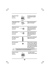
... connect the CPU fan cable to this connector and match the black wire to the ground pin. Please connect an ATX power supply to this connector. ATX 12V Connector (4-pin ATX12V1) (see p.8, No. 8) Please connect the chassis fan cable to this connector and match the black wire to the ground pin. Please install the heatsink and the CPU fan before installing ATX 12V connector; Serial port connector (9-pin COM1) (see p.8, No. 17) PLED+ PLEDPWRBTN# GND 1 DUMMY RESET# GND HDLEDHDLED+ 1 SPEAKER DUMMY DUMMY +5V This header accommodates...
... connect the CPU fan cable to this connector and match the black wire to the ground pin. Please connect an ATX power supply to this connector. ATX 12V Connector (4-pin ATX12V1) (see p.8, No. 8) Please connect the chassis fan cable to this connector and match the black wire to the ground pin. Please install the heatsink and the CPU fan before installing ATX 12V connector; Serial port connector (9-pin COM1) (see p.8, No. 17) PLED+ PLEDPWRBTN# GND 1 DUMMY RESET# GND HDLEDHDLED+ 1 SPEAKER DUMMY DUMMY +5V This header accommodates...
User Manual
Page 19
.... Please insert a floppy diskette into your optical drive to boot your system. Windows 98 / Windows ME does not support RAID functions. 2. Insert the ASRock Support CD into the floppy drive, and press . STEP 2: Use "SATA RAID BIOS" to set RAID configuration, you can start to install Windows 2000 / Windows XP on the screen, "Do you want to generate Serial ATA driver diskette [YN]?", press . After the installation of system boot-up, press key,and then a window for boot devices selection appears...
.... Please insert a floppy diskette into your optical drive to boot your system. Windows 98 / Windows ME does not support RAID functions. 2. Insert the ASRock Support CD into the floppy drive, and press . STEP 2: Use "SATA RAID BIOS" to set RAID configuration, you can start to install Windows 2000 / Windows XP on the screen, "Do you want to generate Serial ATA driver diskette [YN]?", press . After the installation of system boot-up, press key,and then a window for boot devices selection appears...
User Manual
Page 21
... Advanced To set up the advanced BIOS features H/W Monitor To display current hardware status Boot To set up the default system device to enter the BIOS SETUP UTILITY after POST, restart the system by pressing + + , or by turning the system off and then back on the system chassis. BIOS SETUP UTILITY 3.1 Introduction This section explains how to use the BIOS SETUP UTILITY to enter the BIOS SETUP UTILITY, otherwise, POST will continue with the following BIOS setup screens and descriptions...
... Advanced To set up the advanced BIOS features H/W Monitor To display current hardware status Boot To set up the default system device to enter the BIOS SETUP UTILITY after POST, restart the system by pressing + + , or by turning the system off and then back on the system chassis. BIOS SETUP UTILITY 3.1 Introduction This section explains how to use the BIOS SETUP UTILITY to enter the BIOS SETUP UTILITY, otherwise, POST will continue with the following BIOS setup screens and descriptions...
User Manual
Page 23
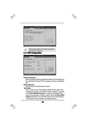
... actual CPU host frequency will be equal to the core speed of this section may cause system to Sub Screen F1 General Help F9 Load Defaults F10 Save and Exit ESC Exit v02.54 (C) Copyright 1985-2003, American Megatrends, Inc. Setting wrong values in this motherboard is "Locked" or "Unlocked". CPU Configuration Chipset Configuration ACPI Configuration IDE Configuration PCIPnP Configuration Floppy Configuration SuperIO Configuration USB Configuration Configure CPU Select Screen Select Item Enter Go to malfunction. BIOS SETUP UTILITY Main Advanced H/W Monitor Boot...
... actual CPU host frequency will be equal to the core speed of this section may cause system to Sub Screen F1 General Help F9 Load Defaults F10 Save and Exit ESC Exit v02.54 (C) Copyright 1985-2003, American Megatrends, Inc. Setting wrong values in this motherboard is "Locked" or "Unlocked". CPU Configuration Chipset Configuration ACPI Configuration IDE Configuration PCIPnP Configuration Floppy Configuration SuperIO Configuration USB Configuration Configure CPU Select Screen Select Item Enter Go to malfunction. BIOS SETUP UTILITY Main Advanced H/W Monitor Boot...
User Manual
Page 24
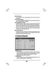
... BIOS SETUP UTILITY Advanced Chipset Configuration DRAM Frequency Flexibility Option DRAM CAS# Latency DRAM Command Rate DRAM Voltage AGP Voltage [Auto] [Disabled] [Auto] [2T Command] [Normal] [High] Options 133MHz 166MHz 200MHz Auto (DDR266) (DDR333) (DDR400) Primary Graphics Adapter AGP Aperture Size AGP Mode AGP Fast Write Onboard AGP Share Memory PCI Delay Transaction OnBoard LAN OnBoard AC'97 Audio Onboard MC'97 Modem [PCI] [64MB] [Auto] [Disabled] [Auto] [Disabled] [Eabled] [Auto] [Auto] +F1 F9 F10 ESC Select Screen Select Item Change Option General Help Load Defaults...
... BIOS SETUP UTILITY Advanced Chipset Configuration DRAM Frequency Flexibility Option DRAM CAS# Latency DRAM Command Rate DRAM Voltage AGP Voltage [Auto] [Disabled] [Auto] [2T Command] [Normal] [High] Options 133MHz 166MHz 200MHz Auto (DDR266) (DDR333) (DDR400) Primary Graphics Adapter AGP Aperture Size AGP Mode AGP Fast Write Onboard AGP Share Memory PCI Delay Transaction OnBoard LAN OnBoard AC'97 Audio Onboard MC'97 Modem [PCI] [64MB] [Auto] [Disabled] [Auto] [Disabled] [Eabled] [Auto] [Auto] +F1 F9 F10 ESC Select Screen Select Item Change Option General Help Load Defaults...
User Manual
Page 25
... [1X]. OnBoard LAN This allows you to enable or disable the feature of the PCI memory address range used for the onboard AC'97 Audio feature. 25 DRAM Voltage Use this to select among [Normal] and [High] for AGP Voltage. DRAM CAS# Latency Use this to select among [2T Command] and [1T Command] for DRAM Command Rate. Configuration options: [Auto], [2.5], [2], and [3]. The default value is set the AGP mode as the primary graphics adapter...
... [1X]. OnBoard LAN This allows you to enable or disable the feature of the PCI memory address range used for the onboard AC'97 Audio feature. 25 DRAM Voltage Use this to select among [Normal] and [High] for AGP Voltage. DRAM CAS# Latency Use this to select among [2T Command] and [1T Command] for DRAM Command Rate. Configuration options: [Auto], [2.5], [2], and [3]. The default value is set the AGP mode as the primary graphics adapter...

User Manual
Page 26
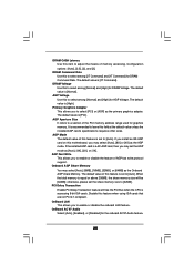
... onboard MC'97 Modem feature. 3.3.3 ACPI Configuration BIOS SETUP UTILITY Advanced ACPI Configuration Suspend To RAM Restore on AC/Power Loss Use this item to set the power state after an unexpected AC/power loss. Restore on AC / Power Loss Ring-In Power On PCI Devices Power On PS / 2 Keyboard Power On RTC Alarm Power On [Disabled] [Power Off] [Disabled] [Disabled] [Disabled] [Disabled] Select auto-detect or disable the STR feature. +F1 F9 F10 ESC Select Screen Select Item Change Option General Help Load Defaults...
... onboard MC'97 Modem feature. 3.3.3 ACPI Configuration BIOS SETUP UTILITY Advanced ACPI Configuration Suspend To RAM Restore on AC/Power Loss Use this item to set the power state after an unexpected AC/power loss. Restore on AC / Power Loss Ring-In Power On PCI Devices Power On PS / 2 Keyboard Power On RTC Alarm Power On [Disabled] [Power Off] [Disabled] [Disabled] [Disabled] [Disabled] Select auto-detect or disable the STR feature. +F1 F9 F10 ESC Select Screen Select Item Change Option General Help Load Defaults...
User Manual
Page 27
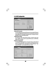
...Primary IDE Controller. IDE Device Configuration You may enable either the primary IDE channel or the secondary IDE channel. BOTH: enables both IDE Controllers. +F1 F9 F10 ESC Select Screen Select Item Change Option General Help Load Defaults Save and Exit Exit v02.54 (C) Copyright 1985-2003, American Megatrends, Inc. SATA Operation Mode Use this option is [RAID]. 3.3.4 IDE Configuration BIOS SETUP UTILITY Advanced IDE Configuration OnBoard IDE Controller SATA Operation Mode Primary IDE Master Primary IDE Slave Secondary IDE Master Secondary IDE Slave [Both] [RAID] [Hard Disk] [Not...
...Primary IDE Controller. IDE Device Configuration You may enable either the primary IDE channel or the secondary IDE channel. BOTH: enables both IDE Controllers. +F1 F9 F10 ESC Select Screen Select Item Change Option General Help Load Defaults Save and Exit Exit v02.54 (C) Copyright 1985-2003, American Megatrends, Inc. SATA Operation Mode Use this option is [RAID]. 3.3.4 IDE Configuration BIOS SETUP UTILITY Advanced IDE Configuration OnBoard IDE Controller SATA Operation Mode Primary IDE Master Primary IDE Slave Secondary IDE Master Secondary IDE Slave [Both] [RAID] [Hard Disk] [Not...
User Manual
Page 28
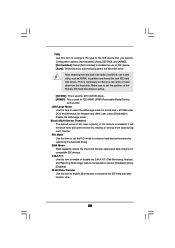
... for Netware and UNIX user, select [Disabled] to enable or disable the S.M.A.R.T. (Self-Monitoring, Analysis, and Reporting Technology) feature. Configuration options: [Not Installed], [Auto], [CD/DVD], and [ARMD]. [Not Installed]: Select [Not Installed] to disable the use a disk utility, such as MO. Block (Multi-Sector Transfer) The default value of IDE device. [Auto]: Select [Auto] to maximize the IDE hard disk data transfer rate. 28 LBA/Large Mode Use this item to enable 32-bit access to automatically detect the hard disk drive.
... for Netware and UNIX user, select [Disabled] to enable or disable the S.M.A.R.T. (Self-Monitoring, Analysis, and Reporting Technology) feature. Configuration options: [Not Installed], [Auto], [CD/DVD], and [ARMD]. [Not Installed]: Select [Not Installed] to disable the use a disk utility, such as MO. Block (Multi-Sector Transfer) The default value of IDE device. [Auto]: Select [Auto] to maximize the IDE hard disk data transfer rate. 28 LBA/Large Mode Use this item to enable 32-bit access to automatically detect the hard disk drive.

User Manual
Page 29
... PCI / PnP Configuration PCI Latency Timer PCI IDE BusMaster [32] [Enabled] Value in units of your floppy drive. PCI Latency Timer The default value is recommended to keep the default value unless the installed PCI expansion cards' specifications require other settings. BIOS SETUP UTILITY Advanced Floppy Configuration Floppy A Floppy B [1.44 MB 312"] [Disabled] Select the type of floppy drive connected to enable or disable the PCI IDE BusMaster feature. 3.3.6 Floppy Configuration In this item to the system. +F1 F9 F10 ESC Select Screen Select Item Change Option...
... PCI / PnP Configuration PCI Latency Timer PCI IDE BusMaster [32] [Enabled] Value in units of your floppy drive. PCI Latency Timer The default value is recommended to keep the default value unless the installed PCI expansion cards' specifications require other settings. BIOS SETUP UTILITY Advanced Floppy Configuration Floppy A Floppy B [1.44 MB 312"] [Disabled] Select the type of floppy drive connected to enable or disable the PCI IDE BusMaster feature. 3.3.6 Floppy Configuration In this item to the system. +F1 F9 F10 ESC Select Screen Select Item Change Option...

User Manual
Page 30
... port. Infrared Port Address Use this item to set to Enable or Disable Floppy Controller. +F1 F9 F10 ESC Select Screen Select Item Change Option General Help Load Defaults Save and Exit Exit v02.54 (C) Copyright 1985-2003, American Megatrends, Inc. Configuration options: [IRQ5] and [IRQ7]. 30 3.3.7 Super IO Configuration BIOS SETUP UTILITY Advanced Configure Super IO Chipset OnBoard Floppy Controller Serial Port Address Infrared Port Address Parallel Port Address Parallel Port Mode EPP Version ECP Mode DMA Channel Parallel Port IRQ [Enabled] [3F8 / IRQ4] [Disabled...
... port. Infrared Port Address Use this item to set to Enable or Disable Floppy Controller. +F1 F9 F10 ESC Select Screen Select Item Change Option General Help Load Defaults Save and Exit Exit v02.54 (C) Copyright 1985-2003, American Megatrends, Inc. Configuration options: [IRQ5] and [IRQ7]. 30 3.3.7 Super IO Configuration BIOS SETUP UTILITY Advanced Configure Super IO Chipset OnBoard Floppy Controller Serial Port Address Infrared Port Address Parallel Port Address Parallel Port Mode EPP Version ECP Mode DMA Channel Parallel Port IRQ [Enabled] [3F8 / IRQ4] [Disabled...

User Manual
Page 31
... USB 2.0 support. USB 2.0 Support Use this item to auto-detect; USB Controller Use this item to enable or disable the support to enable or disable the use of USB controller. Legacy USB Support Use this item to emulate legacy I/O devices such as mouse, keyboard,... 3.3.8 USB Configuration BIOS SETUP UTILITY Advanced USB Configuration USB Devices Enabled : None USB Controller USB 2.0 Support Legacy USB Support [Enabled] [Enabled] [Disabled] To enable or disable the onboard USB controllers. +F1 F9 F10 ESC Select Screen Select Item Change Option General Help Load Defaults...
... USB 2.0 support. USB 2.0 Support Use this item to auto-detect; USB Controller Use this item to enable or disable the support to enable or disable the use of USB controller. Legacy USB Support Use this item to emulate legacy I/O devices such as mouse, keyboard,... 3.3.8 USB Configuration BIOS SETUP UTILITY Advanced USB Configuration USB Devices Enabled : None USB Controller USB 2.0 Support Legacy USB Support [Enabled] [Enabled] [Disabled] To enable or disable the onboard USB controllers. +F1 F9 F10 ESC Select Screen Select Item Change Option General Help Load Defaults...
User Manual
Page 33
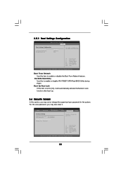
... Boot From Network Use this item to enable or disable VIA VT8237 SATA Raid BIOS Utility during POST. BIOS SETUP UTILITY Main Advanced H/W Monitor Boot Security Exit Security Settings Supervisor Password : Not Installed User Password : Not Installed Change Supervisor Password Change User Password Install or Change the password. Select Screen Select Item Enter Change F1 General Help F9 Load Defaults F10 Save and Exit ESC Exit v02.54 (C) Copyright 1985-2003, American Megatrends, Inc. 33 3.5.1 Boot Settings Configuration BIOS SETUP UTILITY Boot Boot Settings Configuration...
... Boot From Network Use this item to enable or disable VIA VT8237 SATA Raid BIOS Utility during POST. BIOS SETUP UTILITY Main Advanced H/W Monitor Boot Security Exit Security Settings Supervisor Password : Not Installed User Password : Not Installed Change Supervisor Password Change User Password Install or Change the password. Select Screen Select Item Enter Change F1 General Help F9 Load Defaults F10 Save and Exit ESC Exit v02.54 (C) Copyright 1985-2003, American Megatrends, Inc. 33 3.5.1 Boot Settings Configuration BIOS SETUP UTILITY Boot Boot Settings Configuration...
User Manual
Page 35
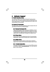
... installed devices. If the Main Menu did not appear automatically, locate and double click on a specific item then follow the installation wizard to visit ASRock's website at http://www.asrock.com; or you need to contact ASRock or want to know more information. 4.2 Support CD Information The Support CD that came with the motherboard contains necessary drivers and useful utilities that the motherboard supports. Because motherboard settings and hardware options vary, use...
... installed devices. If the Main Menu did not appear automatically, locate and double click on a specific item then follow the installation wizard to visit ASRock's website at http://www.asrock.com; or you need to contact ASRock or want to know more information. 4.2 Support CD Information The Support CD that came with the motherboard contains necessary drivers and useful utilities that the motherboard supports. Because motherboard settings and hardware options vary, use...


