User Manual
Page 3
Introduction 5 1.1 Package Contents 5 1.2 Specifications 6 1.3 Motherboard Layout 8 1.4 ASRock I/O Plus 9 TM 2. BIOS SETUP UTILITY 21 3.1 Introduction 21 3.1.1 BIOS Menu Bar 21 3.1.2 Navigation Keys 22 3.2 Main Screen 22 3.3 Advanced Screen 22 3.3.1 CPU Configuration 23 3.3.2 Chipset ...
Introduction 5 1.1 Package Contents 5 1.2 Specifications 6 1.3 Motherboard Layout 8 1.4 ASRock I/O Plus 9 TM 2. BIOS SETUP UTILITY 21 3.1 Introduction 21 3.1.1 BIOS Menu Bar 21 3.1.2 Navigation Keys 22 3.2 Main Screen 22 3.3 Advanced Screen 22 3.3.1 CPU Configuration 23 3.3.2 Chipset ...
User Manual
Page 5
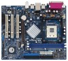
... updated, the content of this manual occur, the updated version will be available on ASRock website as well. ASRock website http://www.asrock.com 1.1 Package Contents ASRock P4VM8 Motherboard (Micro ATX Form Factor: 9.6-in x 8.0-in, 24.4 cm x 20.3 cm) ASRock P4VM8 Quick Installation Guide ASRock P4VM8 Support CD One 80-conductor Ultra ATA 66/100/133 IDE Ribbon Cable One...
... updated, the content of this manual occur, the updated version will be available on ASRock website as well. ASRock website http://www.asrock.com 1.1 Package Contents ASRock P4VM8 Motherboard (Micro ATX Form Factor: 9.6-in x 8.0-in, 24.4 cm x 20.3 cm) ASRock P4VM8 Quick Installation Guide ASRock P4VM8 Support CD One 80-conductor Ultra ATA 66/100/133 IDE Ribbon Cable One...
User Manual
Page 7
... grease between the CPU and the heatsink when you resume the system, please check if the CPU fan on the AGP slot of this motherboard offers stepless control, it back again. It may cause the instability of "Hyper Threading Technology", please check page 24. 2. It may... OS: Microsoft® Windows® 98SE / ME / 2000 / XP compliant CAUTION! 1. ASRock I/O PlusTM: 1 PS/2 mouse port, 1 PS/2 keyboard port, 1 VGA port, 1 parallel port: ECP/EPP support, 6 ready-to-use a 3.3V AGP card on the motherboard functions properly and unplug the power cord, then plug it is detected, the system...
... grease between the CPU and the heatsink when you resume the system, please check if the CPU fan on the AGP slot of this motherboard offers stepless control, it back again. It may cause the instability of "Hyper Threading Technology", please check page 24. 2. It may... OS: Microsoft® Windows® 98SE / ME / 2000 / XP compliant CAUTION! 1. ASRock I/O PlusTM: 1 PS/2 mouse port, 1 PS/2 keyboard port, 1 VGA port, 1 parallel port: ECP/EPP support, 6 ready-to-use a 3.3V AGP card on the motherboard functions properly and unplug the power cord, then plug it is detected, the system...
User Manual
Page 8
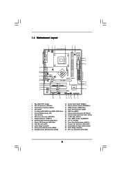
...27 Chassis Fan Connector (CHA_FAN1) 28 Shared USB 2.0 Header (USB4_5, Blue) 29 North Bridge Controller 30 CPU Fan Connector (CPU_FAN1) 8 1.3 Motherboard Layout PS2 Keyboard 1 23 4 20.3cm (8.0 in) PS2 Mouse 1 PS2_USB_PWR1 ATX12V1 56 1 IR1 Super I/O 4Mb BIOS PARALLEL PORT PGA478 VGA1...USB5 LAN PHY 1 AUDIO1 CMOS Battery JR1 JL1 CLRCMOS1 5.1CH CD1 AUX1 Audio CODEC AMR1 VPIMACh80ip0set AGP 8X ATA133 1.5V_AGP1 IDE1 IDE2 PCI 1 ` P4VM8 PCI 2 USB2.0 PCI 3 1 COM1 VIA VT8237R SATA 1 USB67 PANEL 1 PLED PWRBTN 1 1 SPEAKER1 HDLED RESET SATA2 SATA1 DDR400 Prescott 800 DDR1...
...27 Chassis Fan Connector (CHA_FAN1) 28 Shared USB 2.0 Header (USB4_5, Blue) 29 North Bridge Controller 30 CPU Fan Connector (CPU_FAN1) 8 1.3 Motherboard Layout PS2 Keyboard 1 23 4 20.3cm (8.0 in) PS2 Mouse 1 PS2_USB_PWR1 ATX12V1 56 1 IR1 Super I/O 4Mb BIOS PARALLEL PORT PGA478 VGA1...USB5 LAN PHY 1 AUDIO1 CMOS Battery JR1 JL1 CLRCMOS1 5.1CH CD1 AUX1 Audio CODEC AMR1 VPIMACh80ip0set AGP 8X ATA133 1.5V_AGP1 IDE1 IDE2 PCI 1 ` P4VM8 PCI 2 USB2.0 PCI 3 1 COM1 VIA VT8237R SATA 1 USB67 PANEL 1 PLED PWRBTN 1 1 SPEAKER1 HDLED RESET SATA2 SATA1 DDR400 Prescott 800 DDR1...
User Manual
Page 10
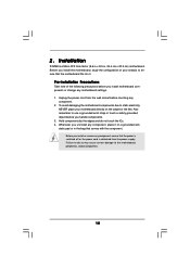
...the power supply. Hold components by the edges and do so may cause severe damage to the motherboard, peripherals, and/or components. 10 Whenever you install the motherboard, study the configuration of the following precautions before you install or remove any component. 2. Also ..., place it . Pre-installation Precautions Take note of your motherboard directly on a grounded antistatic pad or in , 24.4 cm x 20.3 cm) motherboard. To avoid damaging the motherboard components due to do not touch the ICs. 4. Installation P4VM8 is a Micro ATX form factor (9.6-in x 8.0-in the...
...the power supply. Hold components by the edges and do so may cause severe damage to the motherboard, peripherals, and/or components. 10 Whenever you install the motherboard, study the configuration of the following precautions before you install or remove any component. 2. Also ..., place it . Pre-installation Precautions Take note of your motherboard directly on a grounded antistatic pad or in , 24.4 cm x 20.3 cm) motherboard. To avoid damaging the motherboard components due to do not touch the ICs. 4. Installation P4VM8 is a Micro ATX form factor (9.6-in x 8.0-in the...
User Manual
Page 11
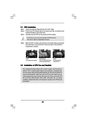
... to a 90° angle. 2.1 CPU Installation Step 1. Unlock the socket by lifting the lever up to the instruction manuals of CPU Fan and Heatsink This motherboard adopts 478-pin CPU socket to improve heat dissipation. DO NOT force the CPU into the socket until it firmly on the side tab to...
... to a 90° angle. 2.1 CPU Installation Step 1. Unlock the socket by lifting the lever up to the instruction manuals of CPU Fan and Heatsink This motherboard adopts 478-pin CPU socket to improve heat dissipation. DO NOT force the CPU into the socket until it firmly on the side tab to...
User Manual
Page 12
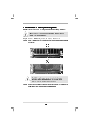
... supply before adding or removing DIMMs or the system components. Step 2. Step 3. 2.3 Installation of Memory Modules (DIMM) P4VM8 motherboard provides two 184-pin DDR (Double Data Rate) DIMM slots. Step 1. Please make sure to the motherboard and the DIMM if you force the DIMM into the slot until the retaining clips at incorrect...
... supply before adding or removing DIMMs or the system components. Step 2. Step 3. 2.3 Installation of Memory Modules (DIMM) P4VM8 motherboard provides two 184-pin DDR (Double Data Rate) DIMM slots. Step 1. Please make sure to the motherboard and the DIMM if you force the DIMM into the slot until the retaining clips at incorrect...
User Manual
Page 13
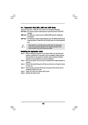
... card connector with screws. Step 5. Before installing the expansion card, please make necessary hardware settings for later use a 3.3V AGP card on P4VM8 motherboard. Please read the documentation of clasp that have the 32-bit PCI interface. Remove the system unit cover (if your AGP card, please check... the slot. Step 6. Installing an expansion card Step 1. Fasten the card to use. AMR slot: The AMR slot is unplugged. The ASRock AGP slot has a special design of the expansion card and make sure that you start the installation. Step 4. Remove the bracket facing the...
... card connector with screws. Step 5. Before installing the expansion card, please make necessary hardware settings for later use a 3.3V AGP card on P4VM8 motherboard. Please read the documentation of clasp that have the 32-bit PCI interface. Remove the system unit cover (if your AGP card, please check... the slot. Step 6. Installing an expansion card Step 1. Fasten the card to use. AMR slot: The AMR slot is unplugged. The ASRock AGP slot has a special design of the expansion card and make sure that you start the installation. Step 4. Remove the bracket facing the...
User Manual
Page 15
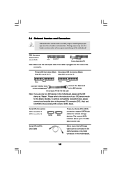
... FDD Connector (33-pin FLOPPY1) (see p.8, No. 10) PIN1 IDE1 PIN1 IDE2 connect the blue end connect the black end to the motherboard to optimize compatibility and performance, please connect your IDE device vendor for internal storage devices. Besides, to the IDE devices 80-conductor ATA 66/...100/133 cable Note: If you use only one IDE device on the motherboard. 15 Primary IDE Connector (Blue) Secondary IDE Connector (Black) (39-pin IDE1, see p.8, No. 11) (39-pin IDE2, see p.8, No. ...
... FDD Connector (33-pin FLOPPY1) (see p.8, No. 10) PIN1 IDE1 PIN1 IDE2 connect the blue end connect the black end to the motherboard to optimize compatibility and performance, please connect your IDE device vendor for internal storage devices. Besides, to the IDE devices 80-conductor ATA 66/...100/133 cable Note: If you use only one IDE device on the motherboard. 15 Primary IDE Connector (Blue) Secondary IDE Connector (Black) (39-pin IDE1, see p.8, No. 11) (39-pin IDE2, see p.8, No. ...
User Manual
Page 18
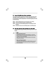
...in working condition. However, please note that supports Serial ATA (SATA) hard disks and RAID functions. STEP 2: Connect the SATA power cable to the motherboard's SATA connector. If SATA HDDs are NOT set for RAID configuration, it cannot perform Hot Plug if the OS has been installed into the drive... bays of the SATA data cable to the SATA hard disk. 2.8 Hot Plug and Hot Swap Functions for SATA HDDs P4VM8 motherboard supports Hot Plug and Hot Swap functions for internal storage devices. If the SATA HDDs are built as RAID1 then it is called "Hot Plug...
...in working condition. However, please note that supports Serial ATA (SATA) hard disks and RAID functions. STEP 2: Connect the SATA power cable to the motherboard's SATA connector. If SATA HDDs are NOT set for RAID configuration, it cannot perform Hot Plug if the OS has been installed into the drive... bays of the SATA data cable to the SATA hard disk. 2.8 Hot Plug and Hot Swap Functions for SATA HDDs P4VM8 motherboard supports Hot Plug and Hot Swap functions for internal storage devices. If the SATA HDDs are built as RAID1 then it is called "Hot Plug...
User Manual
Page 21
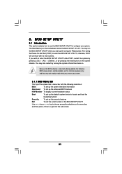
... (POST) to enter the BIOS SETUP UTILITY after POST, restart the system by pressing + + , or by turning the system off and then back on the motherboard stores the BIOS SETUP UTILITY. You may run the BIOS SETUP UTILITY when you start up the security features Exit To exit the current screen...
... (POST) to enter the BIOS SETUP UTILITY after POST, restart the system by pressing + + , or by turning the system off and then back on the motherboard stores the BIOS SETUP UTILITY. You may run the BIOS SETUP UTILITY when you start up the security features Exit To exit the current screen...
User Manual
Page 23
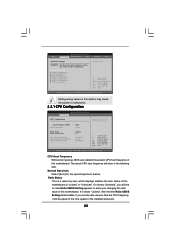
...USB Configuration Configure CPU Select Screen Select Item Enter Go to time the CPU frequency, it shows "Unlocked", you changing the ratio value of this motherboard. Ratio Status This is "Locked" or "Unlocked". CPU Host Frequency While entering setup, BIOS auto detects the present CPU host frequency of this... a read-only item, which displays whether the ratio status of this section may cause system to malfunction. If it will show in this motherboard. If you use the ratio value to Sub Screen F1 General Help F9 Load Defaults F10 Save and Exit ESC Exit v02.54 (C) Copyright 1985...
...USB Configuration Configure CPU Select Screen Select Item Enter Go to time the CPU frequency, it shows "Unlocked", you changing the ratio value of this motherboard. Ratio Status This is "Locked" or "Unlocked". CPU Host Frequency While entering setup, BIOS auto detects the present CPU host frequency of this... a read-only item, which displays whether the ratio status of this section may cause system to malfunction. If it will show in this motherboard. If you use the ratio value to Sub Screen F1 General Help F9 Load Defaults F10 Save and Exit ESC Exit v02.54 (C) Copyright 1985...
User Manual
Page 24
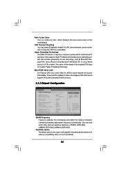
...] to enable P4 CPU internal thermal control mechanism to boot legacy OSes that includes optimization for memory compatibility when it is selected, the motherboard will be enabled in order to keep the CPU from overheated. Max CPUID Value Limit For Prescott CPU only, some OSes (ex. ... set to [Auto] if using Microsoft® Windows® XP, or Linux kernel version 2.4.18 or higher. Hyper Threading Technology To enable this motherboard. Flexibility Option The default value of this option is a read-only item, which displays the ratio actual value of this feature, it requires a...
...] to enable P4 CPU internal thermal control mechanism to boot legacy OSes that includes optimization for memory compatibility when it is selected, the motherboard will be enabled in order to keep the CPU from overheated. Max CPUID Value Limit For Prescott CPU only, some OSes (ex. ... set to [Auto] if using Microsoft® Windows® XP, or Linux kernel version 2.4.18 or higher. Hyper Threading Technology To enable this motherboard. Flexibility Option The default value of this option is a read-only item, which displays the ratio actual value of this feature, it requires a...
User Manual
Page 25
... Audio Select [Auto], [Enabled], or [Disabled] for graphics memory. The default value is [Normal]. The default value is [2T Command]. The default value of this motherboard, you to adjust the means of AGP fast write protocol support.
... Audio Select [Auto], [Enabled], or [Disabled] for graphics memory. The default value is [Normal]. The default value is [2T Command]. The default value of this motherboard, you to adjust the means of AGP fast write protocol support.
User Manual
Page 32
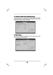
... System Boot. Select Screen Select Item Enter Go to monitor the status of the hardware on your system, including the parameters of the CPU temperature, motherboard temperature, CPU fan speed, chassis fan speed, and the critical voltage. BIOS SETUP UTILITY Main Advanced H/W Monitor Boot Security Exit Hardware Health Event Monitoring CPU...
... System Boot. Select Screen Select Item Enter Go to monitor the status of the hardware on your system, including the parameters of the CPU temperature, motherboard temperature, CPU fan speed, chassis fan speed, and the critical voltage. BIOS SETUP UTILITY Main Advanced H/W Monitor Boot Security Exit Hardware Health Event Monitoring CPU...
User Manual
Page 35
... Support CD to install it. 4.2.4 Contact Information If you may contact your OS documentation for more about ASRock, welcome to activate the devices. 4.2.3 Utilities Menu The Utilities Menu shows the applications software that enhance the motherboard features. 4.2.1 Running The Support CD To begin using the support CD, insert the CD into your...
... Support CD to install it. 4.2.4 Contact Information If you may contact your OS documentation for more about ASRock, welcome to activate the devices. 4.2.3 Utilities Menu The Utilities Menu shows the applications software that enhance the motherboard features. 4.2.1 Running The Support CD To begin using the support CD, insert the CD into your...

