
RAID Installation Guide
Page 2
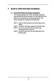
...disks. STEP 4: Connect the other end of the SATA data cable to SATA Hard Disks Installation 1.1 Serial ATA (SATA) Hard Disks Installation This motherboard adopts VIA VT8237 southbridge chipset that supports Serial ATA (SATA) hard disks. Guide to the SATA hard disk. 2 STEP 3: Connect one end... of your chassis. This section will guide you to the motherboard's SATA connector. 1. You may install SATA hard disks on this motherboard for internal storage devices. STEP 2: Connect the SATA power cable to the SATA hard disk.
...disks. STEP 4: Connect the other end of the SATA data cable to SATA Hard Disks Installation 1.1 Serial ATA (SATA) Hard Disks Installation This motherboard adopts VIA VT8237 southbridge chipset that supports Serial ATA (SATA) hard disks. Guide to the SATA hard disk. 2 STEP 3: Connect one end... of your chassis. This section will guide you to the motherboard's SATA connector. 1. You may install SATA hard disks on this motherboard for internal storage devices. STEP 2: Connect the SATA power cable to the SATA hard disk.
RAID Installation Guide
Page 4
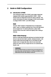
... will improve data access and storage since it does not provide any HDDs of the RAID 0 Disk will introduce the basic knowledge of RAID This motherboard adopts VIA VT8237 south bridge chipset that optimizes two identical hard disk drives to RAID Configurations 2.1 Introduction of RAID, and the guide to configure RAID...
... will improve data access and storage since it does not provide any HDDs of the RAID 0 Disk will introduce the basic knowledge of RAID This motherboard adopts VIA VT8237 south bridge chipset that optimizes two identical hard disk drives to RAID Configurations 2.1 Introduction of RAID, and the guide to configure RAID...
User Manual
Page 3
Introduction 5 1.1 Package Contents 5 1.2 Specifications 6 1.3 Motherboard Layout 8 1.4 ASRock I/O Plus 9 TM 2. BIOS SETUP UTILITY 21 3.1 Introduction 21 3.1.1 BIOS Menu Bar 21 3.1.2 Navigation Keys 22 3.2 Main Screen 22 3.3 Advanced Screen 23 3.3.1 CPU Configuration 23 3.3.2 Chipset ...
Introduction 5 1.1 Package Contents 5 1.2 Specifications 6 1.3 Motherboard Layout 8 1.4 ASRock I/O Plus 9 TM 2. BIOS SETUP UTILITY 21 3.1 Introduction 21 3.1.1 BIOS Menu Bar 21 3.1.2 Navigation Keys 22 3.2 Main Screen 22 3.3 Advanced Screen 23 3.3.1 CPU Configuration 23 3.3.2 Chipset ...
User Manual
Page 5
ASRock website http://www.asrock.com 1.1 Package Contents ASRock P4V88/P4V88+ Motherboard (ATX Form Factor: 12.0-in x 8.6-in, 30.5 cm x 21.8 cm) ASRock P4V88/P4V88+ Quick Installation Guide ASRock P4V88/P4V88+ Support CD One 80-conductor Ultra ATA 66/100/133 IDE Ribbon Cable One Ribbon Cable for purchasing ASRock P4V88/P4V88+ motherboard, a reliable motherboard produced under ASRock's consistently stringent quality control. Because the motherboard specifications and the BIOS software...
ASRock website http://www.asrock.com 1.1 Package Contents ASRock P4V88/P4V88+ Motherboard (ATX Form Factor: 12.0-in x 8.6-in, 30.5 cm x 21.8 cm) ASRock P4V88/P4V88+ Quick Installation Guide ASRock P4V88/P4V88+ Support CD One 80-conductor Ultra ATA 66/100/133 IDE Ribbon Cable One Ribbon Cable for purchasing ASRock P4V88/P4V88+ motherboard, a reliable motherboard produced under ASRock's consistently stringent quality control. Because the motherboard specifications and the BIOS software...
User Manual
Page 7
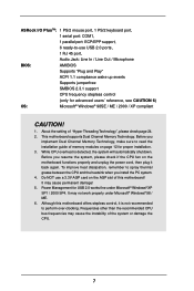
...1. About the setting of the system or damage the CPU. 7 While CPU overheat is not recommended to perform over-clocking. Although this motherboard! Before you implement Dual Channel Memory Technology, make sure to read the installation guide of memory modules on the AGP slot of this...® Windows® XP SP1 / 2000 SP4. It may cause the instability of "Hyper Threading Technology", please check page 24. 2. It may cause permanent damage! 5. ASRock I/O PlusTM: 1 PS/2 mouse port, 1 PS/2 keyboard port, 1 serial port: COM1, 1 parallel port: ECP/EPP support, 6 ready-to-use a 3.3V AGP...
...1. About the setting of the system or damage the CPU. 7 While CPU overheat is not recommended to perform over-clocking. Although this motherboard! Before you implement Dual Channel Memory Technology, make sure to read the installation guide of memory modules on the AGP slot of this...® Windows® XP SP1 / 2000 SP4. It may cause the instability of "Hyper Threading Technology", please check page 24. 2. It may cause permanent damage! 5. ASRock I/O PlusTM: 1 PS/2 mouse port, 1 PS/2 keyboard port, 1 serial port: COM1, 1 parallel port: ECP/EPP support, 6 ready-to-use a 3.3V AGP...
User Manual
Page 8
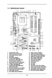
...) 8 Secondary IDE Connector (IDE2, Black) 9 Primary IDE Connector (IDE1, Blue) 10 2 x 184-pin DDR DIMM Slots (Dual Channel B: DDR2, DDR4; 1.3 Motherboard Layout 12 3 45 21.8cm (8.6 in) 67 PS2 Mouse 1 PS2_USB_PWR1 CPU_FAN1 PS2 Keyboard ATX12V1 PARALLEL PORT COM1 PGA478 IDE2 8 DDR1 (64/72 bit, 184-pin...1.5V_AGP1 PCI 1 IDE1 SATA2 Super I/O 2MB BIOS GAME1 PCI 2 USB2.0 FSB800 DDR400 PCI 3 5.1 CH PCI 4 ATA133 SATA PCI 5 1 IR1 P4V88+ VIA VT8237 CMOS Battery CLRCMOS1 FLOPPY1 SATA1 USB67 1 CHA_FAN1 SPEAKER1 1 PANEL 1 PLED PWRBTN 1 HDLED RESET 9 10 11 12 13 14 15 16 ...
...) 8 Secondary IDE Connector (IDE2, Black) 9 Primary IDE Connector (IDE1, Blue) 10 2 x 184-pin DDR DIMM Slots (Dual Channel B: DDR2, DDR4; 1.3 Motherboard Layout 12 3 45 21.8cm (8.6 in) 67 PS2 Mouse 1 PS2_USB_PWR1 CPU_FAN1 PS2 Keyboard ATX12V1 PARALLEL PORT COM1 PGA478 IDE2 8 DDR1 (64/72 bit, 184-pin...1.5V_AGP1 PCI 1 IDE1 SATA2 Super I/O 2MB BIOS GAME1 PCI 2 USB2.0 FSB800 DDR400 PCI 3 5.1 CH PCI 4 ATA133 SATA PCI 5 1 IR1 P4V88+ VIA VT8237 CMOS Battery CLRCMOS1 FLOPPY1 SATA1 USB67 1 CHA_FAN1 SPEAKER1 1 PANEL 1 PLED PWRBTN 1 HDLED RESET 9 10 11 12 13 14 15 16 ...
User Manual
Page 10
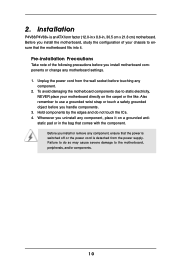
...x 8.6-in the bag that comes with the component. Before you install motherboard components or change any component, ensure that the motherboard fits into it on the carpet or the like. Failure to the motherboard, peripherals, and/or components. 10 Unplug the power cord from the power...do not touch the ICs. 4. Whenever you handle components. 3. Pre-installation Precautions Take note of your motherboard directly on a grounded antistatic pad or in , 30.5 cm x 21.8 cm) motherboard. Installation P4V88/P4V88+ is detached from the wall socket before you uninstall any component. 2.
...x 8.6-in the bag that comes with the component. Before you install motherboard components or change any component, ensure that the motherboard fits into it on the carpet or the like. Failure to the motherboard, peripherals, and/or components. 10 Unplug the power cord from the power...do not touch the ICs. 4. Whenever you handle components. 3. Pre-installation Precautions Take note of your motherboard directly on a grounded antistatic pad or in , 30.5 cm x 21.8 cm) motherboard. Installation P4V88/P4V88+ is detached from the wall socket before you uninstall any component. 2.
User Manual
Page 11
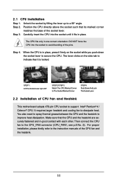
... lifting the lever up to improve heat dissipation. Carefully insert the CPU into the socket to the instruction manuals of CPU Fan and Heatsink This motherboard adopts 478-pin CPU socket to support Intel® Pentium® 4 / Celeron® CPU. You also need to spray thermal grease between the CPU and...
... lifting the lever up to improve heat dissipation. Carefully insert the CPU into the socket to the instruction manuals of CPU Fan and Heatsink This motherboard adopts 478-pin CPU socket to support Intel® Pentium® 4 / Celeron® CPU. You also need to spray thermal grease between the CPU and...
User Manual
Page 12
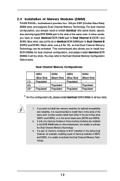
...activate the Dual Channel Memory Technology. 3. If only one memory module or three memory modules are installed in the DDR DIMM slots on this motherboard, it is unable to install identical (the same brand, speed, size and chip-type) DDR DIMM pair in all four slots. 1. ..., you want to install two memory modules, for example, installing a pair of memory modules in the slots of Memory Modules (DIMM) P4V88/P4V88+ motherboard provides four 184-pin DDR (Double Data Rate) DIMM slots, and supports Dual Channel Memory Technology. Black slots; 2.3 Installation of the same color.
...activate the Dual Channel Memory Technology. 3. If only one memory module or three memory modules are installed in the DDR DIMM slots on this motherboard, it is unable to install identical (the same brand, speed, size and chip-type) DDR DIMM pair in all four slots. 1. ..., you want to install two memory modules, for example, installing a pair of memory modules in the slots of Memory Modules (DIMM) P4V88/P4V88+ motherboard provides four 184-pin DDR (Double Data Rate) DIMM slots, and supports Dual Channel Memory Technology. Black slots; 2.3 Installation of the same color.
User Manual
Page 13
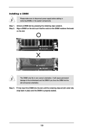
... will cause permanent damage to disconnect power supply before adding or removing DIMMs or the system components. Step 2. Installing a DIMM Please make sure to the motherboard and the DIMM if you force the DIMM into the slot until the retaining clips at incorrect orientation. Step 3. Step 1. Unlock a DIMM slot by pressing...
... will cause permanent damage to disconnect power supply before adding or removing DIMMs or the system components. Step 2. Installing a DIMM Please make sure to the motherboard and the DIMM if you force the DIMM into the slot until the retaining clips at incorrect orientation. Step 3. Step 1. Unlock a DIMM slot by pressing...
User Manual
Page 14
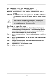
... are 5 PCI slots and 1 AGP slot on P4V88/P4V88+ motherboard. It may cause permanent damage! Remove the system unit cover (if your AGP card, please check with the AGP card vendors. The ASRock AGP slot has a special design of your motherboard is unplugged. Please do NOT use . Remove the...the system cover. 14 Align the card connector with screws. Installing an expansion card Step 1. Step 2. Please read the documentation of this motherboard! Keep the screws for the card before you intend to use a 3.3V AGP card on the slot. Fasten the card to the chassis...
... are 5 PCI slots and 1 AGP slot on P4V88/P4V88+ motherboard. It may cause permanent damage! Remove the system unit cover (if your AGP card, please check with the AGP card vendors. The ASRock AGP slot has a special design of your motherboard is unplugged. Please do NOT use . Remove the...the system cover. 14 Align the card connector with screws. Installing an expansion card Step 1. Step 2. Please read the documentation of this motherboard! Keep the screws for the card before you intend to use a 3.3V AGP card on the slot. Fasten the card to the chassis...
User Manual
Page 16
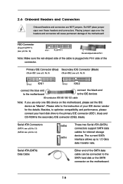
... cable can be connected to the IDE devices 80-conductor ATA 66/100/133 cable Note: If you use only one IDE device on the motherboard. 16 Do NOT place jumper caps over the headers and connectors will cause permanent damage of the connector. Please refer to Pin1 Note: Make ...sure the red-striped side of the cable is plugged into Pin1 side of the motherboard! FDD Connector (33-pin FLOPPY1) (see p.8, No. 12) SATA2 SATA1 These two Serial ATA (SATA) connectors support SATA data cables for the details. Placing jumper...
... cable can be connected to the IDE devices 80-conductor ATA 66/100/133 cable Note: If you use only one IDE device on the motherboard. 16 Do NOT place jumper caps over the headers and connectors will cause permanent damage of the connector. Please refer to Pin1 Note: Make ...sure the red-striped side of the cable is plugged into Pin1 side of the motherboard! FDD Connector (33-pin FLOPPY1) (see p.8, No. 12) SATA2 SATA1 These two Serial ATA (SATA) connectors support SATA data cables for the details. Placing jumper...
User Manual
Page 19
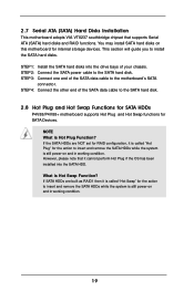
...and in working condition. 19 This section will guide you to the SATA hard disk. 2.8 Hot Plug and Hot Swap Functions for SATA HDDs P4V88/P4V88+ motherboard supports Hot Plug and Hot Swap functions for SATA Devices. STEP 4: Connect the other end of the SATA data cable to install the SATA hard... and remove the SATA HDDs while the system is still power-on and in working condition. 2.7 Serial ATA (SATA) Hard Disks Installation This motherboard adopts VIA VT8237 southbridge chipset that it cannot perform Hot Plug if the OS has been installed into the drive bays of your chassis. STEP...
...and in working condition. 19 This section will guide you to the SATA hard disk. 2.8 Hot Plug and Hot Swap Functions for SATA HDDs P4V88/P4V88+ motherboard supports Hot Plug and Hot Swap functions for SATA Devices. STEP 4: Connect the other end of the SATA data cable to install the SATA hard... and remove the SATA HDDs while the system is still power-on and in working condition. 2.7 Serial ATA (SATA) Hard Disks Installation This motherboard adopts VIA VT8237 southbridge chipset that it cannot perform Hot Plug if the OS has been installed into the drive bays of your chassis. STEP...
User Manual
Page 21
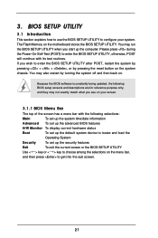
... press to locate and load the Operating System Security To set up the computer. You may also restart by pressing the reset button on the motherboard stores the BIOS SETUP UTILITY. Please press during the Power-On-Self-Test (POST) to enter the BIOS SETUP UTILITY, otherwise, POST will continue with...
... press to locate and load the Operating System Security To set up the computer. You may also restart by pressing the reset button on the motherboard stores the BIOS SETUP UTILITY. Please press during the Power-On-Self-Test (POST) to enter the BIOS SETUP UTILITY, otherwise, POST will continue with...
User Manual
Page 23
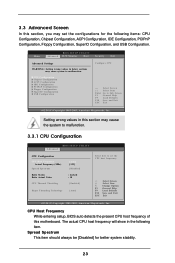
... Select Item Change Option General Help Load Defaults Save and Exit Exit v02.54 (C) Copyright 1985-2003, American Megatrends, Inc. Setting wrong values in this motherboard. Spread Spectrum This item should always be [Disabled] for the following item. Main BIOS SETUP UTILITY Advanced H/W Monitor Boot Security Exit Advanced Settings WARNING : Setting...
... Select Item Change Option General Help Load Defaults Save and Exit Exit v02.54 (C) Copyright 1985-2003, American Megatrends, Inc. Setting wrong values in this motherboard. Spread Spectrum This item should always be [Disabled] for the following item. Main BIOS SETUP UTILITY Advanced H/W Monitor Boot Security Exit Advanced Settings WARNING : Setting...
User Manual
Page 24
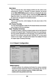
... a read -only item, which displays whether the ratio status of this motherboard. Ratio Actual Value This is a read -only item, which displays the ratio actual value of this motherboard is selected, the motherboard will detect the memory module(s) inserted and assigns appropriate frequency automatically. If ...an Intel Pentium®4 processor that supports Hyper-Threading technology and an operating system that includes optimization for this motherboard. Hyper Threading Technology To enable this feature, it shows "Unlocked", you changing the ratio value of the installed processor.
... a read -only item, which displays whether the ratio status of this motherboard. Ratio Actual Value This is a read -only item, which displays the ratio actual value of this motherboard is selected, the motherboard will detect the memory module(s) inserted and assigns appropriate frequency automatically. If ...an Intel Pentium®4 processor that supports Hyper-Threading technology and an operating system that includes optimization for this motherboard. Hyper Threading Technology To enable this feature, it shows "Unlocked", you changing the ratio value of the installed processor.
User Manual
Page 25
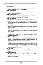
... properly set to [Enabled]. DRAM Command Rate Use this to [Auto]. The default value is [PCI]. If you install an 8X-AGP card on this motherboard, you to a section of AGP fast write protocol support. The default value is accessing 8-bit ISA cards. PCI Delay Transaction Enable PCI Delay Transaction feature...
... properly set to [Enabled]. DRAM Command Rate Use this to [Auto]. The default value is [PCI]. If you install an 8X-AGP card on this motherboard, you to a section of AGP fast write protocol support. The default value is accessing 8-bit ISA cards. PCI Delay Transaction Enable PCI Delay Transaction feature...
User Manual
Page 32
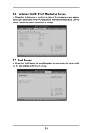
... Monitoring Screen In this section, it allows you to monitor the status of the hardware on your system, including the parameters of the CPU temperature, motherboard temperature, CPU fan speed, chassis fan speed, and the critical voltage. Main Advanced BIOS SETUP UTILITY H/W Monitor Boot Security Exit Boot Settings Boot Settings Configuration...
... Monitoring Screen In this section, it allows you to monitor the status of the hardware on your system, including the parameters of the CPU temperature, motherboard temperature, CPU fan speed, chassis fan speed, and the critical voltage. Main Advanced BIOS SETUP UTILITY H/W Monitor Boot Security Exit Boot Settings Boot Settings Configuration...
User Manual
Page 36
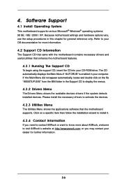
... more information. 4.2 Support CD Information The Support CD that came with the motherboard contains necessary drivers and useful utilities that the motherboard supports. or you need to contact ASRock or want to your CD-ROM drive. 4. Software Support 4.1 Install Operating System This motherboard supports various Microsoft® Windows® operating systems: 98 SE / ME...
... more information. 4.2 Support CD Information The Support CD that came with the motherboard contains necessary drivers and useful utilities that the motherboard supports. or you need to contact ASRock or want to your CD-ROM drive. 4. Software Support 4.1 Install Operating System This motherboard supports various Microsoft® Windows® operating systems: 98 SE / ME...
Quick Installation Guide
Page 1
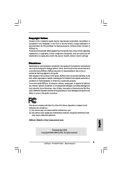
...cause undesired operation. Disclaimer: Specifications and information contained in any form or by the purchaser for a particular purpose. ASRock assumes no event shall ASRock, its directors, officers, employees, or agents be reproduced, transcribed, transmitted, or translated in any language, in...for backup purpose, without notice, and should not be constructed as a commitment by ASRock. All rights reserved. 1 ASRock P4V88/P4V88+ Motherboard English With respect to the contents of this guide, ASRock does not provide warranty of any kind, either expressed or implied, including but ...
...cause undesired operation. Disclaimer: Specifications and information contained in any form or by the purchaser for a particular purpose. ASRock assumes no event shall ASRock, its directors, officers, employees, or agents be reproduced, transcribed, transmitted, or translated in any language, in...for backup purpose, without notice, and should not be constructed as a commitment by ASRock. All rights reserved. 1 ASRock P4V88/P4V88+ Motherboard English With respect to the contents of this guide, ASRock does not provide warranty of any kind, either expressed or implied, including but ...

