User Manual
Page 3
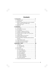
... fan ...2.5 Installation of Memory Modules (DIMM) ...2.6 Expansion Slots (PCI, HDMR, and PCI Express Slots) ...2.7 Jumpers Setup ...2.8 Onboard Headers and Connectors ...2.9 SATAII Hard Disk Setup Guide ...2.10 Serial ATA (SATA) / Serial ATAII (SATAII) Hard Disks Installation ...2.11 Driver Installation Guide ...2.12 HDMR Card and Driver Installation ...2.13 Untied Overclocking Technology ...3.1 Introduction ...3.1.1 BIOS Menu Bar ...3.1.2 Navigation Keys ...3.2 Main Screen ...3.3 Advanced Screen ...3.3.1 CPU Configuration ...3.3.2 Chipset Configuration ...3.3.3 ACPI Configuration ...3.3.4 IDE...
... fan ...2.5 Installation of Memory Modules (DIMM) ...2.6 Expansion Slots (PCI, HDMR, and PCI Express Slots) ...2.7 Jumpers Setup ...2.8 Onboard Headers and Connectors ...2.9 SATAII Hard Disk Setup Guide ...2.10 Serial ATA (SATA) / Serial ATAII (SATAII) Hard Disks Installation ...2.11 Driver Installation Guide ...2.12 HDMR Card and Driver Installation ...2.13 Untied Overclocking Technology ...3.1 Introduction ...3.1.1 BIOS Menu Bar ...3.1.2 Navigation Keys ...3.2 Main Screen ...3.3 Advanced Screen ...3.3.1 CPU Configuration ...3.3.2 Chipset Configuration ...3.3.3 ACPI Configuration ...3.3.4 IDE...
User Manual
Page 4
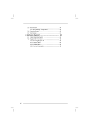
3.5 Boot Screen ...3.5.1 Boot Settings Configuration ...3.6 Security Screen ...3.7 Exit Screen ...4.1 Install Operating System ...4.2 Support CD Information ...4.2.1 Running Support CD ...4.2.2 Drivers Menu ...4.2.3 Utilities Menu ...4.2.4 Contact Information ... 39 39 40 41 42 42 42 42 42 42 4 Software Support ...42 4
3.5 Boot Screen ...3.5.1 Boot Settings Configuration ...3.6 Security Screen ...3.7 Exit Screen ...4.1 Install Operating System ...4.2 Support CD Information ...4.2.1 Running Support CD ...4.2.2 Drivers Menu ...4.2.3 Utilities Menu ...4.2.4 Contact Information ... 39 39 40 41 42 42 42 42 42 42 4 Software Support ...42 4

User Manual
Page 8
... chipset limitation, the actual memory size may be overclocked to SATAII connector, please read "Untied Overclocking Technology" on page 16 for USB 2.0 works fine under Windows® XP, Windows® XP 64-bit, Windows® VistaTM and Windows® VistaTM 64-bit. Frequencies other than 4GB for the reservation for details. For audio output, this motherboard supports both stereo and mono modes. Before installing SATAII hard disk to 115MHz. Although this motherboard offers stepless control...
... chipset limitation, the actual memory size may be overclocked to SATAII connector, please read "Untied Overclocking Technology" on page 16 for USB 2.0 works fine under Windows® XP, Windows® XP 64-bit, Windows® VistaTM and Windows® VistaTM 64-bit. Frequencies other than 4GB for the reservation for details. For audio output, this motherboard supports both stereo and mono modes. Before installing SATAII hard disk to 115MHz. Although this motherboard offers stepless control...

User Manual
Page 10
...Speaker Header (SPEAKER 1) Chassis Fan Connector (CHA_FAN1) USB 2.0 Header (USB6_7, Blue) USB 2.0 Header (USB4_5, Blue) Floppy Connector (FLOPPY1) HDMR Slot (HDMR1) Front Panel Audio Header (HD_AUDIO1) PCI Slots (PCI1- 2) Internal Audio Connector: CD1 (Black) PCI Express x1 Slot (PCIE2) PCI Express x16 Slot (PCIE1) ATX Power Connector (ATXPWR1) BIOS FWH Chip Serial Port Connector (COM1) Infrared Module Header (IR1) 10 1.4 Motherboard Layout 1 23 22.9cm (9.0 in) 1 4 5 6 PS2 Mouse PS2_USB_PWR1 CPU_FAN1 ATX12V1 Conroe Presler Dual Core CPU FSB1333 DDRII667 DDRII_1 (64/72 bit, 240-pin...
...Speaker Header (SPEAKER 1) Chassis Fan Connector (CHA_FAN1) USB 2.0 Header (USB6_7, Blue) USB 2.0 Header (USB4_5, Blue) Floppy Connector (FLOPPY1) HDMR Slot (HDMR1) Front Panel Audio Header (HD_AUDIO1) PCI Slots (PCI1- 2) Internal Audio Connector: CD1 (Black) PCI Express x1 Slot (PCIE2) PCI Express x16 Slot (PCIE1) ATX Power Connector (ATXPWR1) BIOS FWH Chip Serial Port Connector (COM1) Infrared Module Header (IR1) 10 1.4 Motherboard Layout 1 23 22.9cm (9.0 in) 1 4 5 6 PS2 Mouse PS2_USB_PWR1 CPU_FAN1 ATX12V1 Conroe Presler Dual Core CPU FSB1333 DDRII667 DDRII_1 (64/72 bit, 240-pin...

User Manual
Page 20
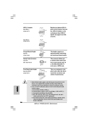
... audio header as a CD-ROM, DVD-ROM, TV tuner card, or MPEG card. B. Enter BIOS Setup Utility. D. Enter Advanced Settings, and then select Chipset Configuration. Set the Front Panel Control option from sound sources such as below: A. MIC_RET and OUT_RET are two USB 2.0 headers on this motherboard. Connect Ground (GND) to install your system. 2. USB 2.0 Headers (9-pin USB6_7) (see p.10 No. 17) 1 USB _ P W R P-7 P +7 GND DU MMY GND P +6 P-6 USB _ P W R Besides four default USB 2.0 ports on the I/O panel, there are for HD audio panel only. This connector allows you use...
... audio header as a CD-ROM, DVD-ROM, TV tuner card, or MPEG card. B. Enter BIOS Setup Utility. D. Enter Advanced Settings, and then select Chipset Configuration. Set the Front Panel Control option from sound sources such as below: A. MIC_RET and OUT_RET are two USB 2.0 headers on this motherboard. Connect Ground (GND) to install your system. 2. USB 2.0 Headers (9-pin USB6_7) (see p.10 No. 17) 1 USB _ P W R P-7 P +7 GND DU MMY GND P +6 P-6 USB _ P W R Besides four default USB 2.0 ports on the I/O panel, there are for HD audio panel only. This connector allows you use...
User Manual
Page 21
... failure to the ground pin. DUMMY RESET# GND HDLEDHDLED+ Chassis Speaker Header (4-pin SPEAKER 1) (see p.10 No. 3) GND +1 2 V C PU_FAN_SPEED FAN_SPEED_ C ONTROL 1 2 3 4 Though this connector. Enter Windows system. If you plan to connect the 3-Pin CPU fan to the CPU fan connector on the lower right hand taskbar to this motherboard provides 4-Pin CPU fan (Quiet Fan) support, the 3-Pin CPU fan still can provides sufficient power. Click "Audio I/O", select "Connector Settings" , choose "Disable front panel jack detection", and save the change by clicking "OK". Chassis Fan...
... failure to the ground pin. DUMMY RESET# GND HDLEDHDLED+ Chassis Speaker Header (4-pin SPEAKER 1) (see p.10 No. 3) GND +1 2 V C PU_FAN_SPEED FAN_SPEED_ C ONTROL 1 2 3 4 Though this connector. Enter Windows system. If you plan to connect the 3-Pin CPU fan to the CPU fan connector on the lower right hand taskbar to this motherboard provides 4-Pin CPU fan (Quiet Fan) support, the 3-Pin CPU fan still can provides sufficient power. Click "Audio I/O", select "Connector Settings" , choose "Disable front panel jack detection", and save the change by clicking "OK". Chassis Fan...
User Manual
Page 23
... mode, which operate with different vendors to correctly adjust your SATAII hard disk to SATAII mode in advance; Western Digital 7 8 5 6 3 4 1 2 If pin 5 and pin 6 are just for details: http://www.hitachigst.com/hdd/support/download.htm The above examples are shorted, SATA 1.5Gb/s will be enabled. Some default setting of different vendors, the jumper pin setting methods may fail to enable SATAII function, please follow the below SATAII hard disk setup guide...
... mode, which operate with different vendors to correctly adjust your SATAII hard disk to SATAII mode in advance; Western Digital 7 8 5 6 3 4 1 2 If pin 5 and pin 6 are just for details: http://www.hitachigst.com/hdd/support/download.htm The above examples are shorted, SATA 1.5Gb/s will be enabled. Some default setting of different vendors, the jumper pin setting methods may fail to enable SATAII function, please follow the below SATAII hard disk setup guide...
User Manual
Page 24
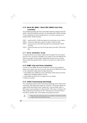
STEP 2: Connect the SATA power cable to install those required drivers. Please follow the steps below then. 1. Install HDMR card driver from [Auto] to your optical drive first. Before you enable Untied Overclocking function, please enter "Overclock Mode" option of the SATA data cable to the motherboard's SATAII connector. Please refer to your system, please insert the support CD to [CPU, PCIE, Async.]. STEP 3: Connect one end of BIOS setup to set the selection from our support CD to the...
STEP 2: Connect the SATA power cable to install those required drivers. Please follow the steps below then. 1. Install HDMR card driver from [Auto] to your optical drive first. Before you enable Untied Overclocking function, please enter "Overclock Mode" option of the SATA data cable to the motherboard's SATAII connector. Please refer to your system, please insert the support CD to [CPU, PCIE, Async.]. STEP 3: Connect one end of BIOS setup to set the selection from our support CD to the...

User Manual
Page 28
... the installed CPU does not support Intel (R) Virtualization Technology. Hyper Threading Technology To enable this function. The C1 state is Intel's new power saving technology. NT4.0) cannot handle the function with "No Execute (NX) Memory Protection" can switch between multiple frequency and voltage points to the IA-32 Intel Architecture. An IA-32 processor with disable. Set to keep the CPU from being used by Vanderpool Technology. This option will...
... the installed CPU does not support Intel (R) Virtualization Technology. Hyper Threading Technology To enable this function. The C1 state is Intel's new power saving technology. NT4.0) cannot handle the function with "No Execute (NX) Memory Protection" can switch between multiple frequency and voltage points to the IA-32 Intel Architecture. An IA-32 processor with disable. Set to keep the CPU from being used by Vanderpool Technology. This option will...

User Manual
Page 29
... Chipset Configuration BIOS SETUP UTILITY Advanced Chipset Configuration DRAM Frequency [Auto] [Disabled] Flexibility Option Configure DRAM Timing by SPD Select [Enabled] will allow you will detect the memory module(s) inserted and assigns appropriate frequency automatically. Configure DRAM Timing by SPD [Enabled] [Auto] DRAM CAS# Latency Primary Graphics Adapter Internal Graphics Mode Select DVMT Mode Select DVMT/FIXED Memory OnBoard HD Audio Front Panel CD-In OnBoard Lan PCI Fix Function VCCM Voltage [PCI] [Auto] [DVMT Mode] [Maximum DVMT] [Auto] [Auto] [Enabled] [Enabled] [Enabled...
... Chipset Configuration BIOS SETUP UTILITY Advanced Chipset Configuration DRAM Frequency [Auto] [Disabled] Flexibility Option Configure DRAM Timing by SPD Select [Enabled] will allow you will detect the memory module(s) inserted and assigns appropriate frequency automatically. Configure DRAM Timing by SPD [Enabled] [Auto] DRAM CAS# Latency Primary Graphics Adapter Internal Graphics Mode Select DVMT Mode Select DVMT/FIXED Memory OnBoard HD Audio Front Panel CD-In OnBoard Lan PCI Fix Function VCCM Voltage [PCI] [Auto] [DVMT Mode] [Maximum DVMT] [Auto] [Auto] [Enabled] [Enabled] [Enabled...

User Manual
Page 30
...DVMT Mode]. The default value is [PCI]. In DVMT mode, the graphics driver allocates memory as [DVMT Mode]. Configuration options: [64MB], [128MB] and [Maximum DVMT]. Configuration options: [2 DRAM Clocks], [3 DRAM Clocks], [4 DRAM Clocks], [5 DRAM Clocks], and [6 DRAM Clocks]. the onboard VGA will be enabled without the installation of DRAM clocks for the onboard HD Audio feature. DVMT Mode Select Use this option to 64MB of the system memory is plugged. 30 In Fixed mode, a fixed-size fragment of dynamically-allotted memory. DVMT (Dynamic Video Memory Technology) is...
...DVMT Mode]. The default value is [PCI]. In DVMT mode, the graphics driver allocates memory as [DVMT Mode]. Configuration options: [64MB], [128MB] and [Maximum DVMT]. Configuration options: [2 DRAM Clocks], [3 DRAM Clocks], [4 DRAM Clocks], [5 DRAM Clocks], and [6 DRAM Clocks]. the onboard VGA will be enabled without the installation of DRAM clocks for the onboard HD Audio feature. DVMT Mode Select Use this option to 64MB of the system memory is plugged. 30 In Fixed mode, a fixed-size fragment of dynamically-allotted memory. DVMT (Dynamic Video Memory Technology) is...

User Manual
Page 35
... enable 32-bit access to enable or disable the PCI IDE BusMaster feature. 35 S.M.A.R.T. PCI IDE BusMaster Use this item to keep the default value unless the installed PCI expansion cards' specifications require other settings. Use this item to maximize the IDE hard disk data transfer rate. 3.3.5 PCIPnP Configuration BIOS SETUP UTILITY Advanced Advanced PCI / PnP Settings PCI Latency Timer PCI IDE BusMaster [32] [Enabled] Value in units of PCI clocks for PCI device latency timer register. +F1 F9 F10 ESC Select Screen Select Item Change Option...
... enable 32-bit access to enable or disable the PCI IDE BusMaster feature. 35 S.M.A.R.T. PCI IDE BusMaster Use this item to keep the default value unless the installed PCI expansion cards' specifications require other settings. Use this item to maximize the IDE hard disk data transfer rate. 3.3.5 PCIPnP Configuration BIOS SETUP UTILITY Advanced Advanced PCI / PnP Settings PCI Latency Timer PCI IDE BusMaster [32] [Enabled] Value in units of PCI clocks for PCI device latency timer register. +F1 F9 F10 ESC Select Screen Select Item Change Option...

User Manual
Page 36
... Enable or Disable Floppy Controller. +F1 F9 F10 ESC Select Screen Select Item Change Option General Help Load Defaults Save and Exit Exit v02.54 (C) Copyright 1985-2005, American Megatrends, Inc. Serial Port Address Use this item to set the address for the onboard serial port or disable it . Configuration options: [Disabled], [2F8 / IRQ3], and [2E8 / IRQ3]. 36 BIOS SETUP UTILITY Advanced Floppy Configuration Floppy A [1.44 MB 31 2"] Select the type of your floppy drive. OnBoard Floppy Controller Use this item to enable or disable floppy drive controller. Configuration options...
... Enable or Disable Floppy Controller. +F1 F9 F10 ESC Select Screen Select Item Change Option General Help Load Defaults Save and Exit Exit v02.54 (C) Copyright 1985-2005, American Megatrends, Inc. Serial Port Address Use this item to set the address for the onboard serial port or disable it . Configuration options: [Disabled], [2F8 / IRQ3], and [2E8 / IRQ3]. 36 BIOS SETUP UTILITY Advanced Floppy Configuration Floppy A [1.44 MB 31 2"] Select the type of your floppy drive. OnBoard Floppy Controller Use this item to enable or disable floppy drive controller. Configuration options...

User Manual
Page 37
... 3.3.8 USB Configuration BIOS SETUP UTILITY Advanced USB Configuration USB Controller USB 2.0 Support Legacy USB Support [Enabled] [Enabled] [Disabled] To enable or disable the onboard USB controllers. +F1 F9 F10 ESC Select Screen Select Item Change Option General Help Load Defaults Save and Exit Exit v02.54 (C) Copyright 1985-2005, American Megatrends, Inc. USB 2.0 Support Use this item to enable or disable the support to enable or disable the USB 2.0 support. Legacy USB Support Use this item to emulate legacy I/O devices such as mouse, keyboard,...etc. ECP Mode DMA Channel Use this...
... 3.3.8 USB Configuration BIOS SETUP UTILITY Advanced USB Configuration USB Controller USB 2.0 Support Legacy USB Support [Enabled] [Enabled] [Disabled] To enable or disable the onboard USB controllers. +F1 F9 F10 ESC Select Screen Select Item Change Option General Help Load Defaults Save and Exit Exit v02.54 (C) Copyright 1985-2005, American Megatrends, Inc. USB 2.0 Support Use this item to enable or disable the support to enable or disable the USB 2.0 support. Legacy USB Support Use this item to emulate legacy I/O devices such as mouse, keyboard,...etc. ECP Mode DMA Channel Use this...
User Manual
Page 42
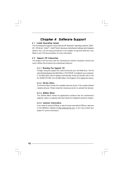
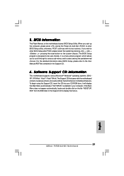
Because motherboard settings and hardware options vary, use the setup procedures in this chapter for more about ASRock, welcome to activate the devices. 4 . 2 . 3 Utilities Menu The Utilities Menu shows the applications software that enhance the motherboard features. 4 . 2 . 1 Running The Support CD To begin using the support CD, insert the CD into your OS documentation for general reference only. Refer to display the menus. 4 . 2 . 2 Drivers Menu The Drivers Menu shows the available devices drivers if...
Because motherboard settings and hardware options vary, use the setup procedures in this chapter for more about ASRock, welcome to activate the devices. 4 . 2 . 3 Utilities Menu The Utilities Menu shows the applications software that enhance the motherboard features. 4 . 2 . 1 Running The Support CD To begin using the support CD, insert the CD into your OS documentation for general reference only. Refer to display the menus. 4 . 2 . 2 Drivers Menu The Drivers Menu shows the available devices drivers if...
Quick Installation Guide
Page 7
... * When you use a FSB1333-CPU on this motherboard supports 2-channel, 4-channel, 6-channel, and 8-channel modes. While CPU overheat is subject to change. You can also connect SATA hard disk to our website in overclocking mode. As long as we have the latest driver, we will operate in the future. This motherboard supports Dual Channel Memory Technology. Please check the table below for Microsoft® Windows® VistaTM / VistaTM 64-bit driver and related information. For audio output, this motherboard, it...
... * When you use a FSB1333-CPU on this motherboard supports 2-channel, 4-channel, 6-channel, and 8-channel modes. While CPU overheat is subject to change. You can also connect SATA hard disk to our website in overclocking mode. As long as we have the latest driver, we will operate in the future. This motherboard supports Dual Channel Memory Technology. Please check the table below for Microsoft® Windows® VistaTM / VistaTM 64-bit driver and related information. For audio output, this motherboard, it...
Quick Installation Guide
Page 16
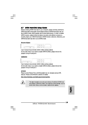
... two USB 2.0 headers on this motherboard. E. Set the Front Panel Control option from sound sources such as below: A. High Definition Audio supports Jack Sensing, but the panel wire on the I/O panel, there are for HD audio panel only. You don't need to function correctly. D. Enter BIOS Setup Utility. Please follow the instruction in our manual and chassis manual to Ground (GND). Enter Advanced Settings, and then select Chipset Configuration. This connector allows you use AC'97 audio panel, please install it to [Enabled]. 16 ASRock P4FSB1333-650 Motherboard...
... two USB 2.0 headers on this motherboard. E. Set the Front Panel Control option from sound sources such as below: A. High Definition Audio supports Jack Sensing, but the panel wire on the I/O panel, there are for HD audio panel only. You don't need to function correctly. D. Enter BIOS Setup Utility. Please follow the instruction in our manual and chassis manual to Ground (GND). Enter Advanced Settings, and then select Chipset Configuration. This connector allows you use AC'97 audio panel, please install it to [Enabled]. 16 ASRock P4FSB1333-650 Motherboard...
Quick Installation Guide
Page 19
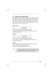
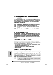
....hitachigst.com/hdd/support/download.htm The above examples are shorted, SATA 1.5Gb/s will be the same. HITACHI Please use the Feature Tool, a DOS-bootable tool, for your computer, please carefully read below instruction with the best performance. In order to enable SATAII function, please follow the below SATAII hard disk setup guide. Please visit the vendors' website for the updates. 19 ASRock P4FSB1333-650 Motherboard English...
....hitachigst.com/hdd/support/download.htm The above examples are shorted, SATA 1.5Gb/s will be the same. HITACHI Please use the Feature Tool, a DOS-bootable tool, for your computer, please carefully read below instruction with the best performance. In order to enable SATAII function, please follow the below SATAII hard disk setup guide. Please visit the vendors' website for the updates. 19 ASRock P4FSB1333-650 Motherboard English...
Quick Installation Guide
Page 20
... motherboard for the possible overclocking risk before you enable Untied Overclocking function, please enter "Overclock Mode" option of the SATA data cable to the SATA / SATAII hard disk. 2.9 Driver Installation Guide To install the drivers to your system, please insert the support CD to your chassis. Before you apply Untied Overclocking Technology. 20 ASRock P4FSB1333-650 Motherboard English This section will guide you finish installing all drivers to your optical drive first. STEP 3: Connect one end of your system now, but PCI / PCIE...
... motherboard for the possible overclocking risk before you enable Untied Overclocking function, please enter "Overclock Mode" option of the SATA data cable to the SATA / SATAII hard disk. 2.9 Driver Installation Guide To install the drivers to your system, please insert the support CD to your chassis. Before you apply Untied Overclocking Technology. 20 ASRock P4FSB1333-650 Motherboard English This section will guide you finish installing all drivers to your optical drive first. STEP 3: Connect one end of your system now, but PCI / PCIE...
Quick Installation Guide
Page 21
... the Support CD to the User Manual (PDF file) contained in your CD-ROM drive. If the Main Menu does not appear automatically, locate and double-click on the motherboard stores BIOS Setup Utility. If you start up the computer, please press during the Power-On-Self-Test (POST) to enter BIOS Setup after POST, please restart the system by pressing + + , or pressing the reset button on the system chassis. To begin using the Support CD...
... the Support CD to the User Manual (PDF file) contained in your CD-ROM drive. If the Main Menu does not appear automatically, locate and double-click on the motherboard stores BIOS Setup Utility. If you start up the computer, please press during the Power-On-Self-Test (POST) to enter BIOS Setup after POST, please restart the system by pressing + + , or pressing the reset button on the system chassis. To begin using the Support CD...


