
User Manual
Page 1
P4FSB1333-650 User Manual Version 1.0 Published July 2007 Copyright©2007 ASRock INC. All rights reserved. 1
P4FSB1333-650 User Manual Version 1.0 Published July 2007 Copyright©2007 ASRock INC. All rights reserved. 1

User Manual
Page 2
... expressed or implied, including but not limited to the owners' benefit, without notice, and should not be constructed as a commitment by ASRock. When you discard the Lithium battery in California, USA, please follow the related regulations in this manual. Copyright Notice: No part of... contains Perchlorate, a toxic substance controlled in this manual may or may apply, see www.dtsc.ca.gov/hazardouswaste/perchlorate" ASRock Website: http://www.asrock.com 2 CALIFORNIA, USA ONLY The Lithium battery adopted on this manual are used only for informational use only and subject ...
... expressed or implied, including but not limited to the owners' benefit, without notice, and should not be constructed as a commitment by ASRock. When you discard the Lithium battery in California, USA, please follow the related regulations in this manual. Copyright Notice: No part of... contains Perchlorate, a toxic substance controlled in this manual may or may apply, see www.dtsc.ca.gov/hazardouswaste/perchlorate" ASRock Website: http://www.asrock.com 2 CALIFORNIA, USA ONLY The Lithium battery adopted on this manual are used only for informational use only and subject ...
User Manual
Page 3
Contents 1 Introduction ...5 1.1 Package Contents ...1.2 Specifications ...1.3 Minimum Hardware Requirement Table for Windows® VistaTM Premium 2007 and Basic Logo...1.4 Motherboard Layout ...1.5 HD 8CH I/O ...2.1 Screw Holes ...2.2 Pre-installation Precautions ...2.3 CPU Installation ...2.4 Installation of Heatsink and CPU fan ...2.5 Installation of Memory Modules (DIMM) ...2.6 Expansion Slots (PCI, HDMR, and PCI Express Slots) ...2.7 Jumpers Setup ...2.8 Onboard Headers and Connectors ...2.9 SATAII Hard Disk Setup Guide ...2.10 Serial ATA (SATA) / Serial ATAII (SATAII) Hard Disks ...
Contents 1 Introduction ...5 1.1 Package Contents ...1.2 Specifications ...1.3 Minimum Hardware Requirement Table for Windows® VistaTM Premium 2007 and Basic Logo...1.4 Motherboard Layout ...1.5 HD 8CH I/O ...2.1 Screw Holes ...2.2 Pre-installation Precautions ...2.3 CPU Installation ...2.4 Installation of Heatsink and CPU fan ...2.5 Installation of Memory Modules (DIMM) ...2.6 Expansion Slots (PCI, HDMR, and PCI Express Slots) ...2.7 Jumpers Setup ...2.8 Onboard Headers and Connectors ...2.9 SATAII Hard Disk Setup Guide ...2.10 Serial ATA (SATA) / Serial ATAII (SATAII) Hard Disks ...
User Manual
Page 4
3.5 Boot Screen ...3.5.1 Boot Settings Configuration ...3.6 Security Screen ...3.7 Exit Screen ...4.1 Install Operating System ...4.2 Support CD Information ...4.2.1 Running Support CD ...4.2.2 Drivers Menu ...4.2.3 Utilities Menu ...4.2.4 Contact Information ... 39 39 40 41 42 42 42 42 42 42 4 Software Support ...42 4
3.5 Boot Screen ...3.5.1 Boot Settings Configuration ...3.6 Security Screen ...3.7 Exit Screen ...4.1 Install Operating System ...4.2 Support CD Information ...4.2.1 Running Support CD ...4.2.2 Drivers Menu ...4.2.3 Utilities Menu ...4.2.4 Contact Information ... 39 39 40 41 42 42 42 42 42 42 4 Software Support ...42 4
User Manual
Page 5
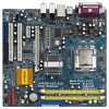
...further notice. You may find the latest VGA cards and CPU support lists on ASRock website without notice. ASRock website http://www.asrock.com 1.1 Package Contents ASRock P4FSB1333-650 Motherboard Bundled With Selected CPU Operating at FSB1333 / 2.66GHz (Micro ATX Form ..., 24.4 cm x 22.9 cm) ASRock P4FSB1333-650 Quick Installation Guide ASRock P4FSB1333-650 Support CD One 80-conductor Ultra ATA 66/100 IDE Ribbon Cable One Ribbon Cable for purchasing ASRock P4FSB1333-650 motherboard, a reliable motherboard produced under ASRock's consistently stringent quality control. It delivers excellent...
...further notice. You may find the latest VGA cards and CPU support lists on ASRock website without notice. ASRock website http://www.asrock.com 1.1 Package Contents ASRock P4FSB1333-650 Motherboard Bundled With Selected CPU Operating at FSB1333 / 2.66GHz (Micro ATX Form ..., 24.4 cm x 22.9 cm) ASRock P4FSB1333-650 Quick Installation Guide ASRock P4FSB1333-650 Support CD One 80-conductor Ultra ATA 66/100 IDE Ribbon Cable One Ribbon Cable for purchasing ASRock P4FSB1333-650 motherboard, a reliable motherboard produced under ASRock's consistently stringent quality control. It delivers excellent...

User Manual
Page 6
.../2 Mouse Port - 1 x PS/2 Keyboard Port - 1 x VGA Port - 1 x Parallel Port (ECP/EPP Support) 6 Support DDRII667/533 (see CAUTION 7) - Pixel Shader 2.0, DirectX 9.0 - Northbridge: Intel® 945GC A2 - ASRock U-COP (see CAUTION 4). Supports Wake-On-LAN HD 8CH I /O - LGA 775 for Intel® Dual Core CoreTM 2 Extreme / CoreTM 2 Duo / Pentium® D / Pentium® Dual...
.../2 Mouse Port - 1 x PS/2 Keyboard Port - 1 x VGA Port - 1 x Parallel Port (ECP/EPP Support) 6 Support DDRII667/533 (see CAUTION 7) - Pixel Shader 2.0, DirectX 9.0 - Northbridge: Intel® 945GC A2 - ASRock U-COP (see CAUTION 4). Supports Wake-On-LAN HD 8CH I /O - LGA 775 for Intel® Dual Core CoreTM 2 Extreme / CoreTM 2 Duo / Pentium® D / Pentium® Dual...

User Manual
Page 7
Connector BIOS Feature Support CD Hardware Monitor OS Certifications - 4 x Ready-to the components and devices of your own risk and expense. AMBIOS 2.3.1 Support - Chassis Fan Tachometer - Voltage Monitoring: +12V, +5V, +3.3V, Vcore - CD in the BIOS, applying Untied Overclocking Technology, or using the thirdparty overclocking tools. FCC, CE, WHQL WARNING Please realize that there is a certain risk involved with overclocking, including adjusting the setting in header - Drivers, Utilities, AntiVirus Software (Trial Version) - CPU Temperature Sensing - Microsoft® ...
Connector BIOS Feature Support CD Hardware Monitor OS Certifications - 4 x Ready-to the components and devices of your own risk and expense. AMBIOS 2.3.1 Support - Chassis Fan Tachometer - Voltage Monitoring: +12V, +5V, +3.3V, Vcore - CD in the BIOS, applying Untied Overclocking Technology, or using the thirdparty overclocking tools. FCC, CE, WHQL WARNING Please realize that there is a certain risk involved with overclocking, including adjusting the setting in header - Drivers, Utilities, AntiVirus Software (Trial Version) - CPU Temperature Sensing - Microsoft® ...

User Manual
Page 8
... situation, PCIE frequency will operate in the future. Please check Intel® website for the CPU FSB frequency and its corresponding memory support frequency. ASRock website http://www.asrock.com 6. 8 Please read the installation guide of the system or damage the 7. Please check the table below for the latest information. Power Management...
... situation, PCIE frequency will operate in the future. Please check Intel® website for the CPU FSB frequency and its corresponding memory support frequency. ASRock website http://www.asrock.com 6. 8 Please read the installation guide of the system or damage the 7. Please check the table below for the latest information. Power Management...

User Manual
Page 9
... Vista TM Premium 2007 and Basic Logo For system integrators and users who purchase this motherboard, please refer to Premium Discrete requirement at http://www.asrock.com * After June 1, 2007, all Windows® VistaTM systems are required to meet above minimum hardware requirements in order to submit Windows® VistaTM Premium...
... Vista TM Premium 2007 and Basic Logo For system integrators and users who purchase this motherboard, please refer to Premium Discrete requirement at http://www.asrock.com * After June 1, 2007, all Windows® VistaTM systems are required to meet above minimum hardware requirements in order to submit Windows® VistaTM Premium...

User Manual
Page 10
...: LINE IN Center: FRONT PCI Dual Channel 27 Super IO Top: SIDE SPK Bottom: CTR BASS Center: REAR SPK 4Mb BIOS Intel 945GC A2 Chipset P4FSB1333-650 USB 2.0 T: USB0 B: USB1 Top: RJ-45 24.4cm (9.6 in) 28 USB 2.0 T: USB2 B: USB3 DDRII_2 (64/72 bit, 240-pin module) FSB800 FSB800 1 IR1 PS2 Keyboard...
...: LINE IN Center: FRONT PCI Dual Channel 27 Super IO Top: SIDE SPK Bottom: CTR BASS Center: REAR SPK 4Mb BIOS Intel 945GC A2 Chipset P4FSB1333-650 USB 2.0 T: USB0 B: USB1 Top: RJ-45 24.4cm (9.6 in) 28 USB 2.0 T: USB2 B: USB3 DDRII_2 (64/72 bit, 240-pin module) FSB800 FSB800 1 IR1 PS2 Keyboard...

User Manual
Page 11
Please select "Mixer ToolBox" , click "Enable playback multi-streaming", and click "ok". See the table below for Audio Output Connection Audio Output Channels Front Speaker Rear Speaker 2 4 6 8 (No. 7) V V V V (No. 4) -V V V Central / Bass (No. 5) --V V Side Speaker (No. 3) ---V * To enable Multi-Streaming function, you are allowed to select "Realtek HDA Primary output" to use Rear Speaker, Central/Bass, and Front Speaker, or select "Realtek HDA Audio 2nd output" to the front panel audio header. Choose "2CH", "4CH", "6CH", or "8CH" and then you need to connect a front panel audio cable...
Please select "Mixer ToolBox" , click "Enable playback multi-streaming", and click "ok". See the table below for Audio Output Connection Audio Output Channels Front Speaker Rear Speaker 2 4 6 8 (No. 7) V V V V (No. 4) -V V V Central / Bass (No. 5) --V V Side Speaker (No. 3) ---V * To enable Multi-Streaming function, you are allowed to select "Realtek HDA Primary output" to use Rear Speaker, Central/Bass, and Front Speaker, or select "Realtek HDA Audio 2nd output" to the front panel audio header. Choose "2CH", "4CH", "6CH", or "8CH" and then you need to connect a front panel audio cable...

User Manual
Page 12
... or the power cord is a Micro ATX form factor (9.6" x 9.0", 24.4 x 22.9 cm) motherboard. Whenever you uninstall any component. 2. Make sure to the chassis. Chapter 2 Installation P4FSB1333-650 is detached from the wall socket before you handle components. 3. Before you install or remove any motherboard settings. 1. Before you install the motherboard, study the...
... or the power cord is a Micro ATX form factor (9.6" x 9.0", 24.4 x 22.9 cm) motherboard. Whenever you uninstall any component. 2. Make sure to the chassis. Chapter 2 Installation P4FSB1333-650 is detached from the wall socket before you handle components. 3. Before you install or remove any motherboard settings. 1. Before you install the motherboard, study the...
User Manual
Page 13
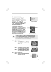
...66GHz. Rotate the load plate to insert the CPU into the socket, please check if the CPU surface is unclean or if there is found. ASRock CPU Sticker 775-Pin Socket Overview Before you may adopt other CPU on this motherboard for upgrade purpose. Step 1. If the stickers are marked with...and out on this motherboard. 2.3 CPU Installation This motherboard is not responsible for the after service of the bundled CPU. Please do not remove ASRock CPU stickers on both sides of Intel 775-LAND CPU, please follow the steps below. Disengaging the lever by the edges where are damaged, ...
...66GHz. Rotate the load plate to insert the CPU into the socket, please check if the CPU surface is unclean or if there is found. ASRock CPU Sticker 775-Pin Socket Overview Before you may adopt other CPU on this motherboard for upgrade purpose. Step 1. If the stickers are marked with...and out on this motherboard. 2.3 CPU Installation This motherboard is not responsible for the after service of the bundled CPU. Please do not remove ASRock CPU stickers on both sides of Intel 775-LAND CPU, please follow the steps below. Disengaging the lever by the edges where are damaged, ...

User Manual
Page 14
Step 2-3. While pressing down lightly on center of the CPU with right hand thumb and peel the cap from the socket while pressing on load plate, engage the load lever. Secure load lever with IHS (Integrated Heat Sink) up. Step 2-2. Verify that the CPU is recommended to use the cap tab to match the two orientation key notches of PnP cap to the orient keys. Close the socket: Step 4-1. Step 4-2. Step 3. Remove PnP Cap (Pick and Place Cap): Use your left hand index finger and thumb to support the load plate edge, engage PnP cap with the two alignment keys of load ...
Step 2-3. While pressing down lightly on center of the CPU with right hand thumb and peel the cap from the socket while pressing on load plate, engage the load lever. Secure load lever with IHS (Integrated Heat Sink) up. Step 2-2. Verify that the CPU is recommended to use the cap tab to match the two orientation key notches of PnP cap to the orient keys. Close the socket: Step 4-1. Step 4-2. Step 3. Remove PnP Cap (Pick and Place Cap): Use your left hand index finger and thumb to support the load plate edge, engage PnP cap with the two alignment keys of load ...

User Manual
Page 15
2.4 Installation of your CPU fan and heatsink. Then connect the CPU fan to the CPU_FAN connector (CPU_FAN1, see page 10, No. 3). Ensure that supports Intel 775-LAND CPU. Step 4. Step 6. Secure excess cable with tie-wrap to illustrate the installation of the heatsink for 775-LAND CPU. For proper installation, please kindly refer to the instruction manuals of CPU Fan and Heatsink This motherboard is an example to ensure cable does not interfere with fan operation or contact other . Ensure fan cables are securely fastened and in good contact with thumb to the...
2.4 Installation of your CPU fan and heatsink. Then connect the CPU fan to the CPU_FAN connector (CPU_FAN1, see page 10, No. 3). Ensure that supports Intel 775-LAND CPU. Step 4. Step 6. Secure excess cable with tie-wrap to illustrate the installation of the heatsink for 775-LAND CPU. For proper installation, please kindly refer to the instruction manuals of CPU Fan and Heatsink This motherboard is an example to ensure cable does not interfere with fan operation or contact other . Ensure fan cables are securely fastened and in good contact with thumb to the...

User Manual
Page 16
... DIMM may be damaged. If you force the DIMM into the slot until the retaining clips at single channel mode. 1. 2. 2.5 Installation of Memory Modules (DIMM) P4FSB1333-650 motherboard provides two 240-pin DDRII (Double Data Rate) DIMM slots, and supports Dual Channel Memory Technology. Align a DIMM on the slot such that the...
... DIMM may be damaged. If you force the DIMM into the slot until the retaining clips at single channel mode. 1. 2. 2.5 Installation of Memory Modules (DIMM) P4FSB1333-650 motherboard provides two 240-pin DDRII (Double Data Rate) DIMM slots, and supports Dual Channel Memory Technology. Align a DIMM on the slot such that the...
User Manual
Page 17
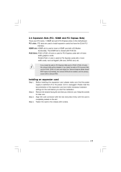
2.6 Expansion Slots (PCI, HDMR and PCI Express Slots) There are used to install expansion cards that the power supply is switched off or the power cord is used to insert a HDMR card with v.92 Modem functionality. Before installing the expansion card, please make necessary hardware settings for PCI Express cards with x16 lane width graphics cards. Keep the screws for PCI Express cards with x1 lane width cards, such as Gigabit LAN card, SATA2 card, etc. Fasten the card to [Enabled], the onboard VGA will be enabled, and the primary screen will be onboard VGA. HDMR slot: HDMR ...
2.6 Expansion Slots (PCI, HDMR and PCI Express Slots) There are used to install expansion cards that the power supply is switched off or the power cord is used to insert a HDMR card with v.92 Modem functionality. Before installing the expansion card, please make necessary hardware settings for PCI Express cards with x16 lane width graphics cards. Keep the screws for PCI Express cards with x1 lane width cards, such as Gigabit LAN card, SATA2 card, etc. Fasten the card to [Enabled], the onboard VGA will be enabled, and the primary screen will be onboard VGA. HDMR slot: HDMR ...
User Manual
Page 18
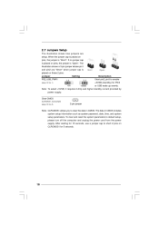
Jumper Setting PS2_USB_PWR1 1_2 2_3 Description Short pin2, pin3 to enable (see p.10 No. 8) 2-pin jumper Note: CLRCMOS1 allows you to clear the data in CMOS includes system setup information such as system password, date, time, and system setup parameters. Note: To select +5VSB, it requires 2 Amp and higher standby current provided by power supply. After waiting for 15 seconds, use a jumper cap to default setup, please turn off the computer and unplug the power cord from the power supply. The illustration shows a 3-pin jumper whose pin1 and pin2 are setup. 2.7 Jumpers Setup The ...
Jumper Setting PS2_USB_PWR1 1_2 2_3 Description Short pin2, pin3 to enable (see p.10 No. 8) 2-pin jumper Note: CLRCMOS1 allows you to clear the data in CMOS includes system setup information such as system password, date, time, and system setup parameters. Note: To select +5VSB, it requires 2 Amp and higher standby current provided by power supply. After waiting for 15 seconds, use a jumper cap to default setup, please turn off the computer and unplug the power cord from the power supply. The illustration shows a 3-pin jumper whose pin1 and pin2 are setup. 2.7 Jumpers Setup The ...

User Manual
Page 19
Placing jumper caps over these headers and connectors. Primary IDE connector (Blue) (39-pin IDE1, see p.10 No. 7) PIN1 IDE 1 connect the black end connect the blue end to the IDE devices to the motherboard 80-conductor ATA 66/100 cable Note: Please refer to the power connector of your IDE device vendor for internal storage devices. Serial ATAII Connectors (SATAII_1: see p.10, No. 14) (SATAII_2: see p.10, No. 12) (SATAII_3: see p.10, No. 10) (SATAII_4: see p.10 No. 19) Pin 1 FLOPPY 1 the red-striped side to 3.0 Gb/s data transfer rate. Then connect the white end of SATA power ...
Placing jumper caps over these headers and connectors. Primary IDE connector (Blue) (39-pin IDE1, see p.10 No. 7) PIN1 IDE 1 connect the black end connect the blue end to the IDE devices to the motherboard 80-conductor ATA 66/100 cable Note: Please refer to the power connector of your IDE device vendor for internal storage devices. Serial ATAII Connectors (SATAII_1: see p.10, No. 14) (SATAII_2: see p.10, No. 12) (SATAII_3: see p.10, No. 10) (SATAII_4: see p.10 No. 19) Pin 1 FLOPPY 1 the red-striped side to 3.0 Gb/s data transfer rate. Then connect the white end of SATA power ...

User Manual
Page 20
Internal Audio Connector (4-pin CD1) (CD1: see p.10 No. 23) C D -L GND GND CD -R CD1 Front Panel Audio Header (9-pin HD_AUDIO1) (see p.10 No. 29) 1 IRTX + 5 VSB DUMMY GND IRRX This header supports an optional wireless transmitting and receiving infrared module. Connect Mic_IN (MIC) to [Enabled]. 20 E. Set the Front Panel Control option from sound sources such as below: A. High Definition Audio supports Jack Sensing, but the panel wire on the chassis must support HDA to install your system. 2. B. D. This is an interface for front panel audio cable that allows ...
Internal Audio Connector (4-pin CD1) (CD1: see p.10 No. 23) C D -L GND GND CD -R CD1 Front Panel Audio Header (9-pin HD_AUDIO1) (see p.10 No. 29) 1 IRTX + 5 VSB DUMMY GND IRRX This header supports an optional wireless transmitting and receiving infrared module. Connect Mic_IN (MIC) to [Enabled]. 20 E. Set the Front Panel Control option from sound sources such as below: A. High Definition Audio supports Jack Sensing, but the panel wire on the chassis must support HDA to install your system. 2. B. D. This is an interface for front panel audio cable that allows ...