User Manual
Page 2
...the implied warranties or conditions of merchantability or fitness for a particular purpose. CALIFORNIA, USA ONLY The Lithium battery adopted on this motherboard contains Perchlorate, a toxic substance controlled in Perchlorate Best Management Practices (BMP) regulations passed by the purchaser for any errors or...this manual are used only for identification or explanation and to the owners' benefit, without intent to change without written consent of ASRock Inc. In no responsibility for backup purpose, without notice, and should not be liable for any indirect, special, incidental, or...
...the implied warranties or conditions of merchantability or fitness for a particular purpose. CALIFORNIA, USA ONLY The Lithium battery adopted on this motherboard contains Perchlorate, a toxic substance controlled in Perchlorate Best Management Practices (BMP) regulations passed by the purchaser for any errors or...this manual are used only for identification or explanation and to the owners' benefit, without intent to change without written consent of ASRock Inc. In no responsibility for backup purpose, without notice, and should not be liable for any indirect, special, incidental, or...
User Manual
Page 3
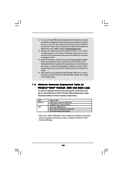
... 5 1.1 Package Contents 5 1.2 Specifications 6 1.3 Minimum Hardware Requirement Table for Windows® VistaTM Premium 2008 and Basic Logo 10 1.4 Motherboard Layout (P43D1600Twins-1394 / P43D1600Twins 11 1.5 Motherboard Layout (P43Twins1600 12 1.6 ASRock 1394_SPDIF I/O (P43D1600Twins-1394 13 1.7 ASRock SPDIF I/O (P43D1600Twins 14 1.8 ASRock SPDIF I/O (P43Twins1600 15 2 Installation 16 2.1 Screw Holes 16 2.2 Pre-installation Precautions 16 2.3 CPU Installation 17 2.4 Installation of Heatsink and CPU...
... 5 1.1 Package Contents 5 1.2 Specifications 6 1.3 Minimum Hardware Requirement Table for Windows® VistaTM Premium 2008 and Basic Logo 10 1.4 Motherboard Layout (P43D1600Twins-1394 / P43D1600Twins 11 1.5 Motherboard Layout (P43Twins1600 12 1.6 ASRock 1394_SPDIF I/O (P43D1600Twins-1394 13 1.7 ASRock SPDIF I/O (P43D1600Twins 14 1.8 ASRock SPDIF I/O (P43Twins1600 15 2 Installation 16 2.1 Screw Holes 16 2.2 Pre-installation Precautions 16 2.3 CPU Installation 17 2.4 Installation of Heatsink and CPU...
User Manual
Page 5
... the latest VGA cards and CPU support lists on ASRock website without notice. www.asrock.com/support/index.asp 1.1 Package Contents ASRock P43D1600Twins-1394 / P43D1600Twins / P43Twins1600 Motherboard (ATX Form Factor: 12.0-in x 9.6-in, 30.5 cm x 24.4 cm) ASRock P43D1600Twins-1394 / P43D1600Twins / P43Twins1600 Quick Installation Guide ASRock P43D1600Twins-1394 / P43D1600Twins / P43Twins1600 Support CD One 80-conductor Ultra ATA 66/100...
... the latest VGA cards and CPU support lists on ASRock website without notice. www.asrock.com/support/index.asp 1.1 Package Contents ASRock P43D1600Twins-1394 / P43D1600Twins / P43Twins1600 Motherboard (ATX Form Factor: 12.0-in x 9.6-in, 30.5 cm x 24.4 cm) ASRock P43D1600Twins-1394 / P43D1600Twins / P43Twins1600 Quick Installation Guide ASRock P43D1600Twins-1394 / P43D1600Twins / P43Twins1600 Support CD One 80-conductor Ultra ATA 66/100...
User Manual
Page 9
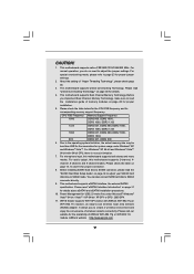
... "Hyper Threading Technology", please check page 45. 3. This motherboard supports Dual Channel Memory Technology. Due to -use wireless local area network (WLAN) adapter. For Windows® XP 64-bit and Windows® VistaTM 64-bit with ASRock WiFi-802.11g or WiFi-802.11n module, an easy... read the "SATAII Hard Disk Setup Guide" on page 40 for details about eSATAII and eSATAII installation procedures. 10. For audio output, this motherboard supports both stereo and mono modes. Please check the table on page 31 for details. 4. For normal operation, you to adjust the jumper ...
... "Hyper Threading Technology", please check page 45. 3. This motherboard supports Dual Channel Memory Technology. Due to -use wireless local area network (WLAN) adapter. For Windows® XP 64-bit and Windows® VistaTM 64-bit with ASRock WiFi-802.11g or WiFi-802.11n module, an easy... read the "SATAII Hard Disk Setup Guide" on page 40 for details about eSATAII and eSATAII installation procedures. 10. For audio output, this motherboard supports both stereo and mono modes. Please check the table on page 31 for details. 4. For normal operation, you to adjust the jumper ...
User Manual
Page 10
... shutdown. Although this motherboard and plan to get the best system performance under Windows® 2000 OS. 12. It is not recommended to use IDE mode under Windows® 2000. Frequencies other than the recommended CPU bus frequencies may cause the instability of ASRock OC Tuner. While ... and the heatsink when you resume the system, please check if the CPU fan on the motherboard functions properly and unplug the power cord, then plug it is a user-friendly ASRock overclocking tool which allows you to surveil your system by hardware monitor function and overclock your hardware...
... shutdown. Although this motherboard and plan to get the best system performance under Windows® 2000 OS. 12. It is not recommended to use IDE mode under Windows® 2000. Frequencies other than the recommended CPU bus frequencies may cause the instability of ASRock OC Tuner. While ... and the heatsink when you resume the system, please check if the CPU fan on the motherboard functions properly and unplug the power cord, then plug it is a user-friendly ASRock overclocking tool which allows you to surveil your system by hardware monitor function and overclock your hardware...
User Manual
Page 11
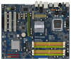
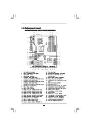
Yellow) 6 2 x 240-pin DDR2 DIMM Slots (Dual Channel B: DDRII_A2, DDRII_B2; 1.4 Motherboard Layout (P43D1600Twins-1394 / P43D1600Twins) 12 3 4 56 7 24.4cm (9.6 in) PS2 Mouse PS2 Keyboard 40 1 PS2_USB_PWR1 Coaxial SPDIF Optical SPDIF 39 38 37 36 35 34 ...
Yellow) 6 2 x 240-pin DDR2 DIMM Slots (Dual Channel B: DDRII_A2, DDRII_B2; 1.4 Motherboard Layout (P43D1600Twins-1394 / P43D1600Twins) 12 3 4 56 7 24.4cm (9.6 in) PS2 Mouse PS2 Keyboard 40 1 PS2_USB_PWR1 Coaxial SPDIF Optical SPDIF 39 38 37 36 35 34 ...
User Manual
Page 12
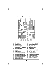
...240-pin DDR3 DIMM Slots (Dual Channel C: DDR3_A1, DDR3_B1; Yellow) 6 2 x 240-pin DDR2 DIMM Slots (Dual Channel B: DDRII_A2, DDRII_B2; 1.5 Motherboard Layout (P43Twins1600) 12 3 24.4cm (9.6 in) 4 56 7 PS2 Mouse PS2 Keyboard 39 1 PS2_USB_PWR1 Coaxial SPDIF Optical SPDIF 38 37 36 35 34 33 32 ... Top: SIDE SPK Center: REAR SPK Bottom: CTR BASS Top: LINE IN Center: FRONT Bottom: MIC IN LAN PCIE1/DE PHY Intel P43 Chipset P43Twins1600 Dual Channel Quad Core CPU Super I/O CD1 AUDIO CODEC 1 HDMI_SPDIF1 1 HD_AUDIO1 COM1 1 PCIE3 PCIE2 PCI Express 2.0 1 FSB3 1 FSB2 PCIE4 1 ...
...240-pin DDR3 DIMM Slots (Dual Channel C: DDR3_A1, DDR3_B1; Yellow) 6 2 x 240-pin DDR2 DIMM Slots (Dual Channel B: DDRII_A2, DDRII_B2; 1.5 Motherboard Layout (P43Twins1600) 12 3 24.4cm (9.6 in) 4 56 7 PS2 Mouse PS2 Keyboard 39 1 PS2_USB_PWR1 Coaxial SPDIF Optical SPDIF 38 37 36 35 34 33 32 ... Top: SIDE SPK Center: REAR SPK Bottom: CTR BASS Top: LINE IN Center: FRONT Bottom: MIC IN LAN PCIE1/DE PHY Intel P43 Chipset P43Twins1600 Dual Channel Quad Core CPU Super I/O CD1 AUDIO CODEC 1 HDMI_SPDIF1 1 HD_AUDIO1 COM1 1 PCIE3 PCIE2 PCI Express 2.0 1 FSB3 1 FSB2 PCIE4 1 ...
User Manual
Page 16
...use a grounded wrist strap or touch a safety grounded object before installing or removing the motherboard. Make sure to unplug the power cord before you handle components. 3. Also remember to motherboard components. 2.1 Screw Holes Place screws into it on the carpet or the like. Before...to do so may cause severe damage to ensure that comes with the component. To avoid damaging the motherboard components due to static electricity, NEVER place your chassis to the motherboard, peripherals, and/or components. 16 Unplug the power cord from the power supply. Before you uninstall...
...use a grounded wrist strap or touch a safety grounded object before installing or removing the motherboard. Make sure to unplug the power cord before you handle components. 3. Also remember to motherboard components. 2.1 Screw Holes Place screws into it on the carpet or the like. Before...to do so may cause severe damage to ensure that comes with the component. To avoid damaging the motherboard components due to static electricity, NEVER place your chassis to the motherboard, peripherals, and/or components. 16 Unplug the power cord from the power supply. Before you uninstall...
User Manual
Page 18
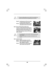
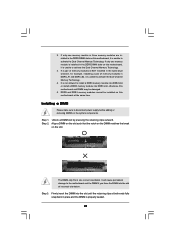
... notches of the CPU with the two alignment keys of load lever. 18 Step 2-4. Step 4. Step 4-2. Step 4-3. This cap must be placed if returning the motherboard for after service. Carefully place the CPU into the socket by using a purely vertical motion. Secure load lever with load plate tab under retention tab...
... notches of the CPU with the two alignment keys of load lever. 18 Step 2-4. Step 4. Step 4-2. Step 4-3. This cap must be placed if returning the motherboard for after service. Carefully place the CPU into the socket by using a purely vertical motion. Secure load lever with load plate tab under retention tab...
User Manual
Page 19
...please kindly refer to ensure cable does not interfere with thumb to install and lock. Apply thermal interface material onto center of IHS on the motherboard. Ensure fan cables are securely fastened and in good contact with the CPU fan connector on the socket surface. Below is equipped with 775-...Pin socket that the CPU and the heatsink are oriented on side closest to the CPU fan connector on the motherboard (CPU_FAN1, see page 11/12, No. 2). Connect fan header with each other components. 19 Secure excess cable with Intel 775-LAND CPU to ...
...please kindly refer to ensure cable does not interfere with thumb to install and lock. Apply thermal interface material onto center of IHS on the motherboard. Ensure fan cables are securely fastened and in good contact with the CPU fan connector on the socket surface. Below is equipped with 775-...Pin socket that the CPU and the heatsink are oriented on side closest to the CPU fan connector on the motherboard (CPU_FAN1, see page 11/12, No. 2). Connect fan header with each other components. 19 Secure excess cable with Intel 775-LAND CPU to ...
User Manual
Page 20
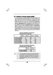
... Channel B (DDRII_A2 and DDRII_B2; Yellow slots; Green slots; see p.11/12 No.7), so that Dual Channel Memory Technology can be activated. This motherboard also allows you have to the Dual Channel Memory Configuration Table below. In other words, you to install them in the set of green slots...them in Dual Channel C (DDR3_A1 and DDR3_B1; see p.11/12 No.6), or identical DDR3 DIMM pair in the slots of Memory Modules (DIMM) This motherboard provides four 240-pin DDR2 (Double Data Rate 2) DIMM slots and two 240-pin DDR3 (Double Data Rate 3) DIMM slots, and supports Dual Channel...
... Channel B (DDRII_A2 and DDRII_B2; Yellow slots; Green slots; see p.11/12 No.7), so that Dual Channel Memory Technology can be activated. This motherboard also allows you have to the Dual Channel Memory Configuration Table below. In other words, you to install them in the set of green slots...them in Dual Channel C (DDR3_A1 and DDR3_B1; see p.11/12 No.6), or identical DDR3 DIMM pair in the slots of Memory Modules (DIMM) This motherboard provides four 240-pin DDR2 (Double Data Rate 2) DIMM slots and two 240-pin DDR3 (Double Data Rate 3) DIMM slots, and supports Dual Channel...
User Manual
Page 21
...the DIMM into the slot at both ends fully snap back in the DDR3 DIMM slots on this motherboard, it is not allowed to install a DDR3 memory module into DDR2 slot or install a DDR2 ... DIMM on the slot such that the notch on the DIMM matches the break on this motherboard at the same time. Firmly insert the DIMM into DDR3 slot; Step 3. DDR2 and DDR3 memory modules cannot... be installed on this motherboard and DIMM may be damaged. 5. Step 2. Unlock a DIMM slot by pressing the retaining clips outward....
...the DIMM into the slot at both ends fully snap back in the DDR3 DIMM slots on this motherboard, it is not allowed to install a DDR3 memory module into DDR2 slot or install a DDR2 ... DIMM on the slot such that the notch on the DIMM matches the break on this motherboard at the same time. Firmly insert the DIMM into DDR3 slot; Step 3. DDR2 and DDR3 memory modules cannot... be installed on this motherboard and DIMM may be damaged. 5. Step 2. Unlock a DIMM slot by pressing the retaining clips outward....
User Manual
Page 22
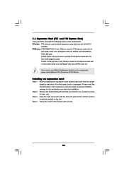
... x16 slot; Green) is unplugged. White) is used for PCI Express cards with x1 lane width cards, such as Gigabit LAN card, SATA2 card and ASRock PCIE_DE card. Remove the bracket facing the slot that you start the installation. 2.6 Expansion Slots (PCI and PCI Express Slots) There are used to the... card, etc. Align the card connector with the slot and press firmly until the card is used for the card before you intend to use ASRock DeskExpress function on this motherboard, please install ASRock PCIE_DE card on this...
... x16 slot; Green) is unplugged. White) is used for PCI Express cards with x1 lane width cards, such as Gigabit LAN card, SATA2 card and ASRock PCIE_DE card. Remove the bracket facing the slot that you start the installation. 2.6 Expansion Slots (PCI and PCI Express Slots) There are used to the... card, etc. Align the card connector with the slot and press firmly until the card is used for the card before you intend to use ASRock DeskExpress function on this motherboard, please install ASRock PCIE_DE card on this...
User Manual
Page 24
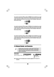
.... Please refer to below jumper settings. 4_5 FSB3 FSB2 4_5 FSB1 1_2 If you want to overclock the CPU you adopt to FSB1333 on this motherboard, you need to adjust the jumpers. Please refer to Pin1 Note: Make sure the red-striped side of the cable is plugged into Pin1 side... FSB3 FSB2 3_4 FSB1 1_2 2.8 Onboard Headers and Connectors Onboard headers and connectors are NOT jumpers. Otherwise, the CPU may not work properly on this motherboard. Please short pin3, pin4 for FSB2 jumper and pin4, pin5 for FSB3 jumper. FDD connector (33-pin FLOPPY1) (see p.11 No. 25 or p.12 No...
.... Please refer to below jumper settings. 4_5 FSB3 FSB2 4_5 FSB1 1_2 If you want to overclock the CPU you adopt to FSB1333 on this motherboard, you need to adjust the jumpers. Please refer to Pin1 Note: Make sure the red-striped side of the cable is plugged into Pin1 side... FSB3 FSB2 3_4 FSB1 1_2 2.8 Onboard Headers and Connectors Onboard headers and connectors are NOT jumpers. Otherwise, the CPU may not work properly on this motherboard. Please short pin3, pin4 for FSB2 jumper and pin4, pin5 for FSB3 jumper. FDD connector (33-pin FLOPPY1) (see p.11 No. 25 or p.12 No...
User Manual
Page 25
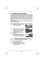
Please read "eSATAII Interface Introduction" on this motherboard. You can be connected to eSATAII connector to 3.0 Gb/s data transfer rate. The current SATAII interface allows up to support eSATAII device. SATAII_6 (Port5) connector ... instruction of your IDE device vendor for internal storage devices. eSATAII Connector (eSATAII_TOP: see p.11/12 No. 8) PIN1 IDE1 connect the blue end to the motherboard connect the black end to the IDE devices 80-conductor ATA 66/100/133 cable Note: Please refer to connect SATAII_6 (Port5) connector and eSATAII...
Please read "eSATAII Interface Introduction" on this motherboard. You can be connected to eSATAII connector to 3.0 Gb/s data transfer rate. The current SATAII interface allows up to support eSATAII device. SATAII_6 (Port5) connector ... instruction of your IDE device vendor for internal storage devices. eSATAII Connector (eSATAII_TOP: see p.11/12 No. 8) PIN1 IDE1 connect the blue end to the motherboard connect the black end to the IDE devices 80-conductor ATA 66/100/133 cable Note: Please refer to connect SATAII_6 (Port5) connector and eSATAII...
User Manual
Page 26
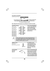
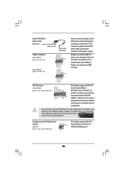
... USB_PWR Please connect the black end of wireless network connectivity. Besides six default USB 2.0 ports on the I/O panel, there are two USB 2.0 headers on this motherboard, this header, please refer to the power connector of the power supply. Each USB 2.0 header can be used as a 4-Pin USB 2.0 header to the ... USB device cable to this header can support two USB 2.0 ports. It allows you don't plan to -use WiFi+AP functin on this picture for ASRock DeskExpress. 26 WiFi/E Header (15-pin WIFI/E) (see p.11 No. 26 or p.12, No. 25) IRTX +5VSB Hotplug# 1 GND IRRX This header ...
... USB_PWR Please connect the black end of wireless network connectivity. Besides six default USB 2.0 ports on the I/O panel, there are two USB 2.0 headers on this motherboard, this header, please refer to the power connector of the power supply. Each USB 2.0 header can be used as a 4-Pin USB 2.0 header to the ... USB device cable to this header can support two USB 2.0 ports. It allows you don't plan to -use WiFi+AP functin on this picture for ASRock DeskExpress. 26 WiFi/E Header (15-pin WIFI/E) (see p.11 No. 26 or p.12, No. 25) IRTX +5VSB Hotplug# 1 GND IRRX This header ...
User Manual
Page 28
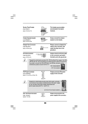
Though this connector and match the black wire to the ground pin. GND +12V CHA_FAN_SPEED Please connect a chassis fan cable to this motherboard provides 4-Pin CPU fan (Quiet Fan) support, the 3-Pin CPU fan still can still work successfully even without the fan speed control function... 1 DUMMY RESET# GND HDLEDHDLED+ This header accommodates several system front panel functions. 1 SPEAKER DUMMY DUMMY +5V Please connect the chassis speaker to this motherboard, please connect it can work if you plan to connect the 3-Pin CPU fan to the CPU fan connector on this header. To use the...
Though this connector and match the black wire to the ground pin. GND +12V CHA_FAN_SPEED Please connect a chassis fan cable to this motherboard provides 4-Pin CPU fan (Quiet Fan) support, the 3-Pin CPU fan still can still work successfully even without the fan speed control function... 1 DUMMY RESET# GND HDLEDHDLED+ This header accommodates several system front panel functions. 1 SPEAKER DUMMY DUMMY +5V Please connect the chassis speaker to this motherboard, please connect it can work if you plan to connect the 3-Pin CPU fan to the CPU fan connector on this header. To use the...
User Manual
Page 29
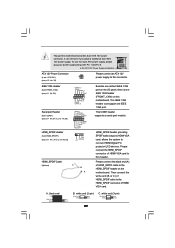
... blue black SPDIFOUT GND blue black SPDIFOUT GND blue black 29 Though this header. A. Please connect the HDMI_SPDIF connector of HDMI_SPDIF cable to this motherboard. IEEE 1394 Header (9-pin FRONT_1394) (see p.11 No. 23) RXTPAM_0 GND RXTPBM_0 +12V GND 1 +12V RXTPBP_0 GND RXTPAP_0 Serial port ...on this connector. Please connect the black end (A) of HDMI VGA card to this motherboard provides 8-pin ATX 12V power connector, it can support one IEEE 1394 header (FRONT_1394) on the motherboard. black end B. To use the 4-pin ATX power supply, please plug your ...
... blue black SPDIFOUT GND blue black SPDIFOUT GND blue black 29 Though this header. A. Please connect the HDMI_SPDIF connector of HDMI_SPDIF cable to this motherboard. IEEE 1394 Header (9-pin FRONT_1394) (see p.11 No. 23) RXTPAM_0 GND RXTPBM_0 +12V GND 1 +12V RXTPBP_0 GND RXTPAP_0 Serial port ...on this connector. Please connect the black end (A) of HDMI VGA card to this motherboard provides 8-pin ATX 12V power connector, it can support one IEEE 1394 header (FRONT_1394) on the motherboard. black end B. To use the 4-pin ATX power supply, please plug your ...
User Manual
Page 30
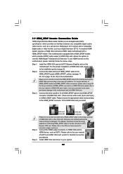
...connect HDMI Digital TV/projector/LCD devices. Please refer to your system. 30 A complete HDMI system requires a HDMI VGA card and a HDMI ready motherboard with a HDMI_SPDIF header, which provides an interface between any compatible digital audio/ video source, such as a set-top box, DVD player, A/V...driver to the VGA card user manual for detailed connection procedures. Step 2. Make sure to correctly connect the HDMI_SPDIF cable to the motherboard and the HDMI VGA card according to HDMI device, such as a digital television (DTV). For the pin definition of PCI Express ...
...connect HDMI Digital TV/projector/LCD devices. Please refer to your system. 30 A complete HDMI system requires a HDMI VGA card and a HDMI ready motherboard with a HDMI_SPDIF header, which provides an interface between any compatible digital audio/ video source, such as a set-top box, DVD player, A/V...driver to the VGA card user manual for detailed connection procedures. Step 2. Make sure to correctly connect the HDMI_SPDIF cable to the motherboard and the HDMI VGA card according to HDMI device, such as a digital television (DTV). For the pin definition of PCI Express ...
User Manual
Page 31
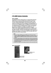
... as " option in IDE mode, please insert or remove your SATAII hard disk. NOTE: 1. 2.10 eSATAII Interface Introduction What is supported with eSATAII devices. This motherboard supports eSATAII interface, the external SATAII specification.
... as " option in IDE mode, please insert or remove your SATAII hard disk. NOTE: 1. 2.10 eSATAII Interface Introduction What is supported with eSATAII devices. This motherboard supports eSATAII interface, the external SATAII specification.

