
User Manual
Page 2
..., and (2) this device must accept any means, except duplication of documentation by the purchaser for backup purpose, without written consent of ASRock Inc. Products and corporate names appearing in this motherboard contains Perchlorate, a toxic substance controlled in this manual are used only for identification or explanation and to infringe. Operation is subject...
..., and (2) this device must accept any means, except duplication of documentation by the purchaser for backup purpose, without written consent of ASRock Inc. Products and corporate names appearing in this motherboard contains Perchlorate, a toxic substance controlled in this manual are used only for identification or explanation and to infringe. Operation is subject...
User Manual
Page 3
... Bar 33 3.1.2 Navigation Keys 34 3.2 Main Screen 34 3.3 OC Tweaker Screen 35 3.4 Advanced Screen 40 3.4.1 CPU Configuration 41 3.4.2 Chipset Configuration 42 3 Introduction 5 1.1 Package Contents 5 1.2 Specifications 6 1.3 Motherboard Layout (N68C-GS FX / N68C-S FX 12 1.4 I/O Panel (N68C-GS FX 13 1.5 I/O Panel (N68C-S FX 14 2 .
... Bar 33 3.1.2 Navigation Keys 34 3.2 Main Screen 34 3.3 OC Tweaker Screen 35 3.4 Advanced Screen 40 3.4.1 CPU Configuration 41 3.4.2 Chipset Configuration 42 3 Introduction 5 1.1 Package Contents 5 1.2 Specifications 6 1.3 Motherboard Layout (N68C-GS FX / N68C-S FX 12 1.4 I/O Panel (N68C-GS FX 13 1.5 I/O Panel (N68C-S FX 14 2 .
User Manual
Page 5
... to BIOS setup and information of this motherboard, please visit our website for purchasing ASRock N68C-GS FX / N68C-S FX motherboard, a reliable motherboard produced under ASRock's consistently stringent quality control. www.asrock.com/support/index.asp 1.1 Package Contents One ASRock N68C-GS FX / N68C-S FX Motherboard (Micro ATX Form Factor: 9.6-in x 8.2-in, 24.4 cm x 20.8 cm) One ASRock N68C-GS FX / N68C-S FX Quick Installation Guide One ASRock N68C-GS FX / N68C-S FX Support CD Two Serial ATA (SATA) Data...
... to BIOS setup and information of this motherboard, please visit our website for purchasing ASRock N68C-GS FX / N68C-S FX motherboard, a reliable motherboard produced under ASRock's consistently stringent quality control. www.asrock.com/support/index.asp 1.1 Package Contents One ASRock N68C-GS FX / N68C-S FX Motherboard (Micro ATX Form Factor: 9.6-in x 8.2-in, 24.4 cm x 20.8 cm) One ASRock N68C-GS FX / N68C-S FX Quick Installation Guide One ASRock N68C-GS FX / N68C-S FX Support CD Two Serial ATA (SATA) Data...

User Manual
Page 9
...CPU will boost to enjoy an instant performance boost. As long as a simple switch of the BIOS option "ASrock UCC", you want to adopt DDR2 1066 memory module on this motherboard, please refer to 95W. If you can also increase L3 cache size up to the memory support list on... by hardware monitor function and overclock your hardware devices to read the installation guide of ASRock OC Tuner. The maximum shared memory size is supported depends on the AM2+ / AM3 CPU you adopt. This motherboard supports CPU up to 6MB, which allows you implement Dual Channel Memory Technology, make ...
...CPU will boost to enjoy an instant performance boost. As long as a simple switch of the BIOS option "ASrock UCC", you want to adopt DDR2 1066 memory module on this motherboard, please refer to 95W. If you can also increase L3 cache size up to the memory support list on... by hardware monitor function and overclock your hardware devices to read the installation guide of ASRock OC Tuner. The maximum shared memory size is supported depends on the AM2+ / AM3 CPU you adopt. This motherboard supports CPU up to 6MB, which allows you implement Dual Channel Memory Technology, make ...
User Manual
Page 10
...saving and improve power efficiency without entering operating systems first like MS-DOS or Windows®. Please be shared and worked on the same motherboard. 14. In other complicated flash utility. With OC DNA, you - With APP Charger driver installed, you can save your USB flash...you can press key during the POST or press key to BIOS setup menu to your OC settings as iPhone/iPod/iPad Touch, ASRock has prepared a wonderful solution for the operation procedures of . Featuring an advanced proprietary hardware and software design, Intelligent Energy Saver is ...
...saving and improve power efficiency without entering operating systems first like MS-DOS or Windows®. Please be shared and worked on the same motherboard. 14. In other complicated flash utility. With OC DNA, you - With APP Charger driver installed, you can save your USB flash...you can press key during the POST or press key to BIOS setup menu to your OC settings as iPhone/iPod/iPad Touch, ASRock has prepared a wonderful solution for the operation procedures of . Featuring an advanced proprietary hardware and software design, Intelligent Energy Saver is ...

User Manual
Page 11
Although this function for all CPU/DRAM configurations. ASRock motherboards are currently transferring. 18. ASRock website: http://www.asrock.com/Feature/SmartView/index.asp 16. ASRock XFast USB can not guarantee the system stability for keeping the stability of Your Data:..., the system will automatically shutdown. The performance may choose to disable this motherboard offers stepless control, it back again. Real-Time Analysis of your system. 11 This motherboard supports ASRock AM2 Boost overclocking technology. Enabling this function in game. Before you adopt....
Although this function for all CPU/DRAM configurations. ASRock motherboards are currently transferring. 18. ASRock website: http://www.asrock.com/Feature/SmartView/index.asp 16. ASRock XFast USB can not guarantee the system stability for keeping the stability of Your Data:..., the system will automatically shutdown. The performance may choose to disable this motherboard offers stepless control, it back again. Real-Time Analysis of your system. 11 This motherboard supports ASRock AM2 Boost overclocking technology. Enabling this function in game. Before you adopt....
User Manual
Page 12
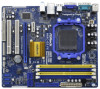
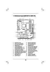
... 7025 / nForce 630a 12 Yellow) 21 Chassis Fan Connector (CHA_FAN1) 7 2 x 240-pin DDR3 DIMM Slots 22 Clear CMOS Jumper (CLRCMOS1) (Dual Channel: DDR3_A1, DDR3_B1; 1.3 Motherboard Layout (N68C-GS FX / N68C-S FX) Designed in Taipei DDRII_1 (64 bit, 240-piFnSmBod8ul0e)0 DDR3_A1 (64 bit, 240-pin module) DDRII_2 (64 bit, 240-piFnSmBod8ul0e)0 DDR3_B1 (64 bit, 240-pin module...
... 7025 / nForce 630a 12 Yellow) 21 Chassis Fan Connector (CHA_FAN1) 7 2 x 240-pin DDR3 DIMM Slots 22 Clear CMOS Jumper (CLRCMOS1) (Dual Channel: DDR3_A1, DDR3_B1; 1.3 Motherboard Layout (N68C-GS FX / N68C-S FX) Designed in Taipei DDRII_1 (64 bit, 240-piFnSmBod8ul0e)0 DDR3_A1 (64 bit, 240-pin module) DDRII_2 (64 bit, 240-piFnSmBod8ul0e)0 DDR3_B1 (64 bit, 240-pin module...
User Manual
Page 15
...use a grounded wrist strap or touch a safety grounded object before touching any component, ensure that the motherboard fits into the screw holes to secure the motherboard to the motherboard, peripherals, and/or components. 1. When placing screws into it on the carpet or the like. ...Installation This is detached from the wall socket before you uninstall any motherboard settings. Before you install motherboard components or change any component, place it . Doing so may cause severe damage to the chassis, please do not ...
...use a grounded wrist strap or touch a safety grounded object before touching any component, ensure that the motherboard fits into the screw holes to secure the motherboard to the motherboard, peripherals, and/or components. 1. When placing screws into it on the carpet or the like. ...Installation This is detached from the wall socket before you uninstall any motherboard settings. Before you install motherboard components or change any component, place it . Doing so may cause severe damage to the chassis, please do not ...

User Manual
Page 16
... the CPU. The CPU fits only in place. When the CPU is in good contact with a small triangle. DO NOT force the CPU into this motherboard, it firmly on the side tab to the CPU FAN connector (CPU_FAN1, see Page 12, No. 2). The lever clicks on the socket while you install...
... the CPU. The CPU fits only in place. When the CPU is in good contact with a small triangle. DO NOT force the CPU into this motherboard, it firmly on the side tab to the CPU FAN connector (CPU_FAN1, see Page 12, No. 2). The lever clicks on the socket while you install...
User Manual
Page 17
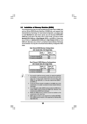
... Channel Memory Technology. 3. In other words, install them in the slots of blue slots (DDR3_A1 and DDR3_B1), or in the DIMM slot on this motherboard at the same time. 5. You may be damaged. 4. DDR2 memory module is not allowed to the Dual Channel Memory Configuration Table below. Yellow slots...have to install identical (the same brand, speed, size and chip-type) DDR2/DDR3 DIMM pair in the slots of Memory Modules (DIMM) This motherboard provides two 240-pin DDR2 (Double Data Rate 2) DIMM slots and two 240-pin DDR3 (Double Data Rate 3) DIMM slots, and supports Dual Channel...
... Channel Memory Technology. 3. In other words, install them in the slots of blue slots (DDR3_A1 and DDR3_B1), or in the DIMM slot on this motherboard at the same time. 5. You may be damaged. 4. DDR2 memory module is not allowed to the Dual Channel Memory Configuration Table below. Yellow slots...have to install identical (the same brand, speed, size and chip-type) DDR2/DDR3 DIMM pair in the slots of Memory Modules (DIMM) This motherboard provides two 240-pin DDR2 (Double Data Rate 2) DIMM slots and two 240-pin DDR3 (Double Data Rate 3) DIMM slots, and supports Dual Channel...

User Manual
Page 18
... DIMM matches the break on the slot. Step 1. Unlock a DIMM slot by pressing the retaining clips outward. Step 2. Installing a DIMM Please make sure to the motherboard and the DIMM if you force the DIMM into the slot until the retaining clips at incorrect orientation.
... DIMM matches the break on the slot. Step 1. Unlock a DIMM slot by pressing the retaining clips outward. Step 2. Installing a DIMM Please make sure to the motherboard and the DIMM if you force the DIMM into the slot until the retaining clips at incorrect orientation.
User Manual
Page 19
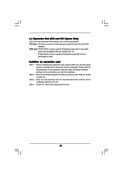
... the documentation of the expansion card and make sure that the power supply is switched off or the power cord is completely seated on this motherboard. 2.4 Expansion Slots (PCI and PCI Express Slots) There are used to install expansion cards that you start the installation. Keep the screws for the card...
... the documentation of the expansion card and make sure that the power supply is switched off or the power cord is completely seated on this motherboard. 2.4 Expansion Slots (PCI and PCI Express Slots) There are used to install expansion cards that you start the installation. Keep the screws for the card...
User Manual
Page 20
... as Secondary. A. Please refer to apply these new values. Connect the D-Sub monitor cable to this motherboard. 4. Boot your system. Click "Extend my Windows desktop onto this motherboard. Right-click the display icon and select "Attached", if necessary. Connect the DVI-D monitor cable to...page 19 for proper expansion card installation procedures for the diaplay icon identified by the number 2. 2.5 Easy Multi Monitor Feature This motherboard supports Multi Monitor upgrade. Please make sure that you have installed the onboard VGA driver already, there is no need to be ...
... as Secondary. A. Please refer to apply these new values. Connect the D-Sub monitor cable to this motherboard. 4. Boot your system. Click "Extend my Windows desktop onto this motherboard. Right-click the display icon and select "Attached", if necessary. Connect the DVI-D monitor cable to...page 19 for proper expansion card installation procedures for the diaplay icon identified by the number 2. 2.5 Easy Multi Monitor Feature This motherboard supports Multi Monitor upgrade. Please make sure that you have installed the onboard VGA driver already, there is no need to be ...

User Manual
Page 22
... storage devices. Primary IDE connector (Blue) (39-pin IDE1, see p.12 No. 9) PIN1 IDE1 connect the blue end to the motherboard connect the black end to the IDE devices 80-conductor ATA 66/100/133 cable Note: Please refer to the instruction of the SATA ... and Connectors Onboard headers and connectors are NOT jumpers. Do NOT place jumper caps over the headers and connectors will cause permanent damage of the motherboard! • Floppy Connector (33-pin FLOPPY1) (see p.12, No. 12) SATAII_1 SATAII_3 (PORT 0.0) (PORT 1.0) SATAII_2 SATAII_4 (PORT 0.1) (PORT 1.1) Serial ATA (SATA)...
... storage devices. Primary IDE connector (Blue) (39-pin IDE1, see p.12 No. 9) PIN1 IDE1 connect the blue end to the motherboard connect the black end to the IDE devices 80-conductor ATA 66/100/133 cable Note: Please refer to the instruction of the SATA ... and Connectors Onboard headers and connectors are NOT jumpers. Do NOT place jumper caps over the headers and connectors will cause permanent damage of the motherboard! • Floppy Connector (33-pin FLOPPY1) (see p.12, No. 12) SATAII_1 SATAII_3 (PORT 0.0) (PORT 1.0) SATAII_2 SATAII_4 (PORT 0.1) (PORT 1.1) Serial ATA (SATA)...

User Manual
Page 23
... for the front panel audio cable that allows convenient connection of audio devices. 1. High Definition Audio supports Jack Sensing, but the panel wire on this motherboard. Please follow the instruction in our manual and chassis manual to receive stereo audio input from sound sources such as below: A. B.
... for the front panel audio cable that allows convenient connection of audio devices. 1. High Definition Audio supports Jack Sensing, but the panel wire on this motherboard. Please follow the instruction in our manual and chassis manual to receive stereo audio input from sound sources such as below: A. B.

User Manual
Page 24
...to the ground pin. Chassis Speaker Header (4-pin SPEAKER 1) (see p.12 No. 8) 12 24 Please connect an ATX power supply to this motherboard, please connect it to the CPU fan connector on this connector. 1 13 24 Connect Ground (GND) to connect them for HD audio panel ...p.12 No. 2) 4 3 2 1 GND +12V CPU_FAN_SPEED FAN_SPEED_CONTROL Please connect the CPU fan cable to this connector and match the black wire to this motherboard provides 4-Pin CPU fan (Quiet Fan) support, the 3-Pin CPU fan still can work successfully even without the fan speed control function. Though this header...
...to the ground pin. Chassis Speaker Header (4-pin SPEAKER 1) (see p.12 No. 8) 12 24 Please connect an ATX power supply to this motherboard, please connect it to the CPU fan connector on this connector. 1 13 24 Connect Ground (GND) to connect them for HD audio panel ...p.12 No. 2) 4 3 2 1 GND +12V CPU_FAN_SPEED FAN_SPEED_CONTROL Please connect the CPU fan cable to this connector and match the black wire to this motherboard provides 4-Pin CPU fan (Quiet Fan) support, the 3-Pin CPU fan still can work successfully even without the fan speed control function. Though this header...
User Manual
Page 25
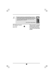
Though this connector. Failing to connect a power supply with Pin 1 and Pin 13. ATX 12V Power Connector (4-pin ATX12V1) (see p.12 No. 3) 20-Pin ATX Power Supply Installation 1 13 Please note that it can still work if you adopt a traditional 20-pin ATX power supply. To use the 20-pin ATX power supply, please plug your power supply along with ATX 12V plug to this motherboard provides 24-pin ATX power connector, 12 24 it is necessary to do so will cause power up failure. 25
Though this connector. Failing to connect a power supply with Pin 1 and Pin 13. ATX 12V Power Connector (4-pin ATX12V1) (see p.12 No. 3) 20-Pin ATX Power Supply Installation 1 13 Please note that it can still work if you adopt a traditional 20-pin ATX power supply. To use the 20-pin ATX power supply, please plug your power supply along with ATX 12V plug to this motherboard provides 24-pin ATX power connector, 12 24 it is necessary to do so will cause power up failure. 25

User Manual
Page 27
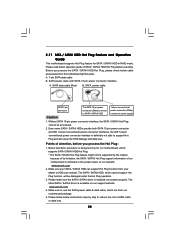
... of the SATA data cable to the SATA / SATAII hard disk. 2 . 1 0 Hot Plug and Hot Swap Functions for SATA / SATAII HDDs This motherboard supports Hot Plug and Hot Swap functions for the action to insert and remove the SATA / SATAII HDDs while the system is called "Hot Plug... still power-on and in working condition. NOTE What is Hot Swap Function? 2 . 9 Serial ATA (SATA) / Serial ATAII (SATAII) Hard Disks Installation This motherboard adopts NVIDIA® GeForce 7025 / nForce 630a chipset that it is called "Hot Swap" for SATA / SATAII Devices. STEP 1: Install the SATA / SATAII hard ...
... of the SATA data cable to the SATA / SATAII hard disk. 2 . 1 0 Hot Plug and Hot Swap Functions for SATA / SATAII HDDs This motherboard supports Hot Plug and Hot Swap functions for the action to insert and remove the SATA / SATAII HDDs while the system is called "Hot Plug... still power-on and in working condition. NOTE What is Hot Swap Function? 2 . 9 Serial ATA (SATA) / Serial ATAII (SATAII) Hard Disks Installation This motherboard adopts NVIDIA® GeForce 7025 / nForce 630a chipset that it is called "Hot Swap" for SATA / SATAII Devices. STEP 1: Install the SATA / SATAII hard ...
User Manual
Page 28
...) connect to use the SATA power cable & data cable, which are from your SATA / SATAII HDD can support Hot Plug function from our motherboard package. 5. Make sure your dealer or HDD user manual. The latest SATA / SATAII driver is installed into system properly. A. 7-pin SATA data... SATAII HDD in the product spec on our support website: www.asrock.com 4. Please follow below operation guide of attention, before you process the SATA / SATAII HDD Hot Plug, please check below cable accessories from the motherboard gift box pack. Make sure to power supply Caution 1. Before...
...) connect to use the SATA power cable & data cable, which are from your SATA / SATAII HDD can support Hot Plug function from our motherboard package. 5. Make sure your dealer or HDD user manual. The latest SATA / SATAII driver is installed into system properly. A. 7-pin SATA data... SATAII HDD in the product spec on our support website: www.asrock.com 4. Please follow below operation guide of attention, before you process the SATA / SATAII HDD Hot Plug, please check below cable accessories from the motherboard gift box pack. Make sure to power supply Caution 1. Before...
User Manual
Page 29
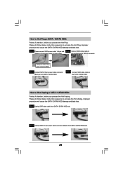
the motherboard's SATAII connector. How to Hot Unplug a SATA / SATAII HDD: Points of attention, before you process the Hot Plug: Please do follow below instruction sequence to ...
the motherboard's SATAII connector. How to Hot Unplug a SATA / SATAII HDD: Points of attention, before you process the Hot Plug: Please do follow below instruction sequence to ...


