User Manual
Page 3
Introduction 5 1.1 Package Contents 5 1.2 Specifications 6 1.3 Motherboard Layout (N68C-GS FX / N68C-S FX 12 1.4 I/O Panel (N68C-GS FX 13 1.5 I/O Panel (N68C-S FX 14 2 . BIOS SETUP UTILITY 33 3.1 Introduction 33 3.1.1 BIOS Menu Bar 33 3.1.2 Navigation Keys 34 3.2 Main Screen 34 3.3 OC Tweaker Screen 35 3.4 Advanced Screen 40 3.4.1 CPU Configuration 41 3.4.2 Chipset Configuration 42 3 Contents 1 . Installation 15 ...
Introduction 5 1.1 Package Contents 5 1.2 Specifications 6 1.3 Motherboard Layout (N68C-GS FX / N68C-S FX 12 1.4 I/O Panel (N68C-GS FX 13 1.5 I/O Panel (N68C-S FX 14 2 . BIOS SETUP UTILITY 33 3.1 Introduction 33 3.1.1 BIOS Menu Bar 33 3.1.2 Navigation Keys 34 3.2 Main Screen 34 3.3 OC Tweaker Screen 35 3.4 Advanced Screen 40 3.4.1 CPU Configuration 41 3.4.2 Chipset Configuration 42 3 Contents 1 . Installation 15 ...
User Manual
Page 5
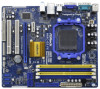
... purchasing ASRock N68C-GS FX / N68C-S FX motherboard, a reliable motherboard produced under ASRock's consistently stringent quality control. Because the motherboard specifications and the BIOS software might be updated, the content of the Support CD. www.asrock.com/support/index.asp 1.1 Package Contents One ASRock N68C-GS FX / N68C-S FX Motherboard (Micro ATX Form Factor: 9.6-in x 8.2-in, 24.4 cm x 20.8 cm) One ASRock N68C-GS FX / N68C-S FX Quick Installation Guide One ASRock N68C-GS FX / N68C-S FX...
... purchasing ASRock N68C-GS FX / N68C-S FX motherboard, a reliable motherboard produced under ASRock's consistently stringent quality control. Because the motherboard specifications and the BIOS software might be updated, the content of the Support CD. www.asrock.com/support/index.asp 1.1 Package Contents One ASRock N68C-GS FX / N68C-S FX Motherboard (Micro ATX Form Factor: 9.6-in x 8.2-in, 24.4 cm x 20.8 cm) One ASRock N68C-GS FX / N68C-S FX Quick Installation Guide One ASRock N68C-GS FX / N68C-S FX...

User Manual
Page 7
... Energy Saver (see CAUTION 9) - 1 x ATA133 IDE connector (supports 2 x IDE devices) - 1 x Floppy connector - 1 x Print Port header - ASRock Instant Flash (see CAUTION 16) - ASRock XFast USB (see CAUTION 12) - ASRock XFast LAN (see CAUTION 18) 7 Supports PXE I /O Connector BIOS Feature Support CD Unique Feature - CPU/Chassis/Power FAN connector - 24 pin ATX power connector - 4 pin 12V...
... Energy Saver (see CAUTION 9) - 1 x ATA133 IDE connector (supports 2 x IDE devices) - 1 x Floppy connector - 1 x Print Port header - ASRock Instant Flash (see CAUTION 16) - ASRock XFast USB (see CAUTION 12) - ASRock XFast LAN (see CAUTION 18) 7 Supports PXE I /O Connector BIOS Feature Support CD Unique Feature - CPU/Chassis/Power FAN connector - 24 pin ATX power connector - 4 pin 12V...

User Manual
Page 8
ASRock U-COP (see CAUTION 20) Hardware - CPU Temperature Sensing Monitor - CPU/Chassis/Power Fan Tachometer - Microsoft® Windows® 7 / 7 64-bit / VistaTM / VistaTM 64-bit / XP / ... WARNING Please realize that there is a certain risk involved with overclocking, including adjusting the setting in the BIOS, applying Untied Overclocking Technology, or using the thirdparty overclocking tools. - ASRock AM2 Boost: ASRock Patented Technology to boost memory performance up to the components and devices of your own risk and expense. Boot Failure Guard...
ASRock U-COP (see CAUTION 20) Hardware - CPU Temperature Sensing Monitor - CPU/Chassis/Power Fan Tachometer - Microsoft® Windows® 7 / 7 64-bit / VistaTM / VistaTM 64-bit / XP / ... WARNING Please realize that there is a certain risk involved with overclocking, including adjusting the setting in the BIOS, applying Untied Overclocking Technology, or using the thirdparty overclocking tools. - ASRock AM2 Boost: ASRock Patented Technology to boost memory performance up to the components and devices of your own risk and expense. Boot Failure Guard...

User Manual
Page 9
... this motherboard, please refer to enjoy an instant performance boost. Please check NVIDIA® website for the operation procedures of the BIOS option "ASrock UCC", you implement Dual Channel Memory Technology, make sure to the memory support list on page 17 for CPU support list....the best system performance under Windows® 7 / VistaTM / XP. CAUTION! 1. Please refer to 95W. As long as a simple switch of ASRock OC Tuner. When UCC feature is no such limitation. 7. Please read the installation guide of memory modules on our website for details. 4. Whether ...
... this motherboard, please refer to enjoy an instant performance boost. Please check NVIDIA® website for the operation procedures of the BIOS option "ASrock UCC", you implement Dual Channel Memory Technology, make sure to the memory support list on page 17 for CPU support list....the best system performance under Windows® 7 / VistaTM / XP. CAUTION! 1. Please refer to 95W. As long as a simple switch of ASRock OC Tuner. When UCC feature is no such limitation. 7. Please read the installation guide of memory modules on our website for details. 4. Whether ...
User Manual
Page 10
...revolutionary technology that the USB flash drive or hard drive must use Intelligent Energy Saver function, please enable Cool 'n' Quiet option in the BIOS setup in Flash ROM. ASRock APP Charger allows you desire a faster, less restricted way of overclocking settings. 11. In other complicated flash utility. The software name...drive, then you can load the OC profile to their own system to access ASRock Instant Flash. With APP Charger driver installed, you can press key during the POST or press key to BIOS setup menu to get the same OC settings as yours! Featuring an advanced ...
...revolutionary technology that the USB flash drive or hard drive must use Intelligent Energy Saver function, please enable Cool 'n' Quiet option in the BIOS setup in Flash ROM. ASRock APP Charger allows you desire a faster, less restricted way of overclocking settings. 11. In other complicated flash utility. The software name...drive, then you can load the OC profile to their own system to access ASRock Instant Flash. With APP Charger driver installed, you can press key during the POST or press key to BIOS setup menu to get the same OC settings as yours! Featuring an advanced ...

User Manual
Page 11
... latency in Game: After setting online game priority higher, it may cause the instability of the device. 17. This motherboard supports ASRock AM2 Boost overclocking technology. Frequencies other than the recommended CPU bus frequencies may not be applicative to perform over-clocking. If your application... that combines your most visited web sites, your history, your Facebook friends and your system. 15. Before you keep in the BIOS setup, the memory performance will improve up to 12.5%, but the effect still depends on the motherboard functions properly and unplug the ...
... latency in Game: After setting online game priority higher, it may cause the instability of the device. 17. This motherboard supports ASRock AM2 Boost overclocking technology. Frequencies other than the recommended CPU bus frequencies may not be applicative to perform over-clocking. If your application... that combines your most visited web sites, your history, your Facebook friends and your system. 15. Before you keep in the BIOS setup, the memory performance will improve up to 12.5%, but the effect still depends on the motherboard functions properly and unplug the ...
User Manual
Page 12
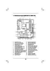
...Memory (8Mb) 30 PCI Express x1 Slot (PCIE1) 15 USB_PWR2 Jumper 31 NVIDIA GeForce 7025 / nForce 630a 12 1.3 Motherboard Layout (N68C-GS FX / N68C-S FX) Designed in Taipei DDRII_1 (64 bit, 240-piFnSmBod8ul0e)0 DDR3_A1 (64 bit, 240-pin module) DDRII_2 (64 bit, 240-piFnSmBod8ul0e)0 ...7025 / nForce 630a SATAII_1 (PORT 0.0) SATAII_3 (PORT 1.0) SATAII_2 (PORT 0.1) SATAII_4 (PORT 1.1) RoHS PCIE2 Support 8-Core CPU PCI1 CMOS BATTERY 8Mb BIOS AUDIO CODEC HD_AUDIO1 PWR_FAN1 FLOPPY1 CD1 1 PCI2 LPT1 1 CLRCMOS1 1 CHA_FAN1 PANEL 1 PLED PWRBTN 1 HDLED RESET SPEAKER1 1 1 USB8_9 1 USB6_7 1 ...
...Memory (8Mb) 30 PCI Express x1 Slot (PCIE1) 15 USB_PWR2 Jumper 31 NVIDIA GeForce 7025 / nForce 630a 12 1.3 Motherboard Layout (N68C-GS FX / N68C-S FX) Designed in Taipei DDRII_1 (64 bit, 240-piFnSmBod8ul0e)0 DDR3_A1 (64 bit, 240-pin module) DDRII_2 (64 bit, 240-piFnSmBod8ul0e)0 ...7025 / nForce 630a SATAII_1 (PORT 0.0) SATAII_3 (PORT 1.0) SATAII_2 (PORT 0.1) SATAII_4 (PORT 1.1) RoHS PCIE2 Support 8-Core CPU PCI1 CMOS BATTERY 8Mb BIOS AUDIO CODEC HD_AUDIO1 PWR_FAN1 FLOPPY1 CD1 1 PCI2 LPT1 1 CLRCMOS1 1 CHA_FAN1 PANEL 1 PLED PWRBTN 1 HDLED RESET SPEAKER1 1 1 USB8_9 1 USB6_7 1 ...
User Manual
Page 20
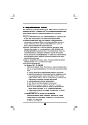
...large number on each monitor. C. With the internal onboard VGA and the external add-on PCI Express VGA card. 3. Click the "Identify" button to enter BIOS setup. When you can adjust the parameters of this monitor". Set the "Screen Resolution" and "Color Quality" as Secondary. D. G. Install the NVIDIA®...; XP / XP 64-bit OS: Right click the desktop, choose "Properties", and select the "Settings" tab so that you do not adjust the BIOS setup, the default value of "Share Memory", [Auto], will be your system. Please refer to the following steps to your card, one , two...
...large number on each monitor. C. With the internal onboard VGA and the external add-on PCI Express VGA card. 3. Click the "Identify" button to enter BIOS setup. When you can adjust the parameters of this monitor". Set the "Screen Resolution" and "Color Quality" as Secondary. D. G. Install the NVIDIA®...; XP / XP 64-bit OS: Right click the desktop, choose "Properties", and select the "Settings" tab so that you do not adjust the BIOS setup, the default value of "Share Memory", [Auto], will be your system. Please refer to the following steps to your card, one , two...

User Manual
Page 22
.... 22 The current SATAII interface allows up to clear the CMOS when you just finish updating the BIOS, you must boot up the system first, and then shut it down before you update the BIOS. Either end of the SATA data cable can be connected to Pin1 Note: Make sure the red...
.... 22 The current SATAII interface allows up to clear the CMOS when you just finish updating the BIOS, you must boot up the system first, and then shut it down before you update the BIOS. Either end of the SATA data cable can be connected to Pin1 Note: Make sure the red...
User Manual
Page 30
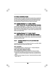
...window for you just want to make a SATA / SATAII driver diskette. B. STEP 2: Make a SATA / SATAII Driver Diskette. B. C. STEP 1: Set Up BIOS. Insert the ASRock Support CD into your optical drive to your system can start to install Windows® 7 / 7 64-bit / VistaTM / VistaTM 64-bit / XP / XP... of system boot-up to bottom side to [IDE]. Besides, there is no need for boot devices selection appears. A. Enter BIOS SETUP UTILITY Advanced screen Storage Configuration. 2.12 Driver Installation Guide To install the drivers to your system, please insert the support CD...
...window for you just want to make a SATA / SATAII driver diskette. B. STEP 2: Make a SATA / SATAII Driver Diskette. B. C. STEP 1: Set Up BIOS. Insert the ASRock Support CD into your optical drive to your system can start to install Windows® 7 / 7 64-bit / VistaTM / VistaTM 64-bit / XP / XP... of system boot-up to bottom side to [IDE]. Besides, there is no need for boot devices selection appears. A. Enter BIOS SETUP UTILITY Advanced screen Storage Configuration. 2.12 Driver Installation Guide To install the drivers to your system, please insert the support CD...
User Manual
Page 31
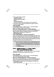
... 4: Use "RAID Installation Guide" to [RAID]. Please refer to start Please insert a floppy diskette into the floppy diskette. STEP 1: Set Up BIOS. B. Set the "SATA Operation Mode" option to set RAID configuration. If you will see these messages, Please insert a blank formatted diskette into floppy... the RAID installation guide in the Support CD: .. \ RAID Installation Guide 31 At the beginning of the document in the following path in BIOS first. Set the "SATA Operation Mode" option to [RAID] in the Support CD: .. \ RAID Installation Guide STEP 5: Install Windows®...
... 4: Use "RAID Installation Guide" to [RAID]. Please refer to start Please insert a floppy diskette into the floppy diskette. STEP 1: Set Up BIOS. B. Set the "SATA Operation Mode" option to set RAID configuration. If you will see these messages, Please insert a blank formatted diskette into floppy... the RAID installation guide in the Support CD: .. \ RAID Installation Guide 31 At the beginning of the document in the following path in BIOS first. Set the "SATA Operation Mode" option to [RAID] in the Support CD: .. \ RAID Installation Guide STEP 5: Install Windows®...
User Manual
Page 32
... rebuild) RAID functions on page 8 for the possible overclocking risk before you enable Untied Overclocking function, please enter "Overclock Mode" option of BIOS setup to set the selection from ASRock support CD. For Windows® 7 / 7 64-bit users, you still need to load RAID driver from [Auto] to [CPU, PCIE, Async.]. Therefore...
... rebuild) RAID functions on page 8 for the possible overclocking risk before you enable Untied Overclocking function, please enter "Overclock Mode" option of BIOS setup to set the selection from ASRock support CD. For Windows® 7 / 7 64-bit users, you still need to load RAID driver from [Auto] to [CPU, PCIE, Async.]. Therefore...

User Manual
Page 33
... of the screen has a menu bar with its test routines. The SPI Memory on the system chassis. Because the BIOS software is constantly being updated, the following BIOS setup screens and descriptions are for reference purpose only, and they may not exactly match what you see on your system...following selections: Main To set up the system time/date information OC Tweaker To set up overclocking features Advanced To set up the advanced BIOS features H/W Monitor To display current hardware status Boot To set up the default system device to locate and load the Operating System Security ...
... of the screen has a menu bar with its test routines. The SPI Memory on the system chassis. Because the BIOS software is constantly being updated, the following BIOS setup screens and descriptions are for reference purpose only, and they may not exactly match what you see on your system...following selections: Main To set up the system time/date information OC Tweaker To set up overclocking features Advanced To set up the advanced BIOS features H/W Monitor To display current hardware status Boot To set up the default system device to locate and load the Operating System Security ...

User Manual
Page 34
...exit the current screen 3.2 Main Screen When you enter the BIOS SETUP UTILITY, the Main screen will appear and display the system overview. System Time [Hour:Minute:Second] Use this item to specify the system time. N68C-GS FX BIOS SETUP UTILITY Main OC Tweaker Advanced H/W Monitor Boot Security ...Exit System Overview System Time System Date [17:00:09] [Thu 12/15/2011] BIOS Version : N68C-GS FX P1.00 Processor Type : AMD Phenom (tm) II X4 910e Processor (64bit) Processor Speed : 2600MHz Microcode Update : 100F43/10000B6 L1 Cache...
...exit the current screen 3.2 Main Screen When you enter the BIOS SETUP UTILITY, the Main screen will appear and display the system overview. System Time [Hour:Minute:Second] Use this item to specify the system time. N68C-GS FX BIOS SETUP UTILITY Main OC Tweaker Advanced H/W Monitor Boot Security ...Exit System Overview System Time System Date [17:00:09] [Thu 12/15/2011] BIOS Version : N68C-GS FX P1.00 Processor Type : AMD Phenom (tm) II X4 910e Processor (64bit) Processor Speed : 2600MHz Microcode Update : 100F43/10000B6 L1 Cache...

User Manual
Page 35
...Main OC Tweaker Advanced H/W Monitor Boot Security Exit System Overview System Time System Date [17:00:09] [Thu 12/15/2011] BIOS Version : N68C-S FX P1.00 Processor Type : AMD Phenom (tm) II X4 910e Processor (64bit) Processor Speed : 2600MHz Microcode Update : 100F43/10000B6 ... Overclock Mode CPU Frequency (MHz) PCIE Frequency (MHz) Boot Failure Guard Boot Failure Guard Count CPU/LDT Spread Spectrum PCIE Spread Spectrum SATA Spread Spectrum ASRock UCC AMD Turbo Core Technology AMD IO C-State Support CPU Active Core Control [Auto] [200] [100] [Enabled] [3] [Enabled] [Enabled] [Enabled] [...
...Main OC Tweaker Advanced H/W Monitor Boot Security Exit System Overview System Time System Date [17:00:09] [Thu 12/15/2011] BIOS Version : N68C-S FX P1.00 Processor Type : AMD Phenom (tm) II X4 910e Processor (64bit) Processor Speed : 2600MHz Microcode Update : 100F43/10000B6 ... Overclock Mode CPU Frequency (MHz) PCIE Frequency (MHz) Boot Failure Guard Boot Failure Guard Count CPU/LDT Spread Spectrum PCIE Spread Spectrum SATA Spread Spectrum ASRock UCC AMD Turbo Core Technology AMD IO C-State Support CPU Active Core Control [Auto] [200] [100] [Enabled] [3] [Enabled] [Enabled] [Enabled] [...

User Manual
Page 36
Configuration options: [Disabled] and [Enabled]. ASRock UCC ASRock UCC (Unlock CPU Core) feature simplifies AMD CPU activation. As long as default. Use this feature. AMD IO C-State Support This allows you to adjust ... a better price. SATA Spread Spectrum This feature will display Processor Maximum Frequency for reference. Please be set to [Enabled] as a simple switch of the BIOS option "ASRock UCC", you can support this option to adjust PCIE frequency. Confi guration options: [Auto] and [Disabled]. CPU Active Core Control This allows you to enable...
Configuration options: [Disabled] and [Enabled]. ASRock UCC ASRock UCC (Unlock CPU Core) feature simplifies AMD CPU activation. As long as default. Use this feature. AMD IO C-State Support This allows you to adjust ... a better price. SATA Spread Spectrum This feature will display Processor Maximum Frequency for reference. Please be set to [Enabled] as a simple switch of the BIOS option "ASRock UCC", you can support this option to adjust PCIE frequency. Confi guration options: [Auto] and [Disabled]. CPU Active Core Control This allows you to enable...

User Manual
Page 37
...item. Processor Voltage It allows you adopt Phenom CPU, there is one of the standard values as listed for system stability. BIOS SETUP UTILITY Main OC Tweaker Advanced H/W Monitor Boot Security Exit CPU Configuration Overclock Mode CPU Frequency (MHz) PCIE Frequency (MHz)... Boot Failure Guard Boot Failure Guard Count CPU/LDT Spread Spectrum PCIE Spread Spectrum SATA Spread Spectrum ASRock UCC AMD Turbo Core Technology AMD IO C-State Support CPU Active Core Control [Auto] [200] [100] [Enabled] [3] [Enabled] [Enabled] [Enabled]...
...item. Processor Voltage It allows you adopt Phenom CPU, there is one of the standard values as listed for system stability. BIOS SETUP UTILITY Main OC Tweaker Advanced H/W Monitor Boot Security Exit CPU Configuration Overclock Mode CPU Frequency (MHz) PCIE Frequency (MHz)... Boot Failure Guard Boot Failure Guard Count CPU/LDT Spread Spectrum PCIE Spread Spectrum SATA Spread Spectrum ASRock UCC AMD Turbo Core Technology AMD IO C-State Support CPU Active Core Control [Auto] [200] [100] [Enabled] [3] [Enabled] [Enabled] [Enabled]...

User Manual
Page 38
Memory Timing BIOS SETUP UTILITY OC Tweaker Memory Timing Memory Controller Mode Power Down Enable Bank Interleaving Channel Interleaving CAS Latency (CL) 7 TRCD 7 TRP 7 TRAS 20 Command Rate 2 ...
Memory Timing BIOS SETUP UTILITY OC Tweaker Memory Timing Memory Controller Mode Power Down Enable Bank Interleaving Channel Interleaving CAS Latency (CL) 7 TRCD 7 TRP 7 TRAS 20 Command Rate 2 ...

User Manual
Page 40
...cause the system to malfunction. Select the proper BIOS file to update your BIOS, and reboot your USB flash drive, floppy disk or hard drive, then you execute ASRock Instant Flash utility, the utility will show the BIOS files and their respective information. Setting wrong values... in a few clicks without entering operating systems first like MS-DOS or Windows®. ASRock Instant Flash ASRock Instant Flash is a BIOS flash utility embedded in below sections may set the configurations for the following items: CPU Configuration, Chipset Configuration, ACPI...
...cause the system to malfunction. Select the proper BIOS file to update your BIOS, and reboot your USB flash drive, floppy disk or hard drive, then you execute ASRock Instant Flash utility, the utility will show the BIOS files and their respective information. Setting wrong values... in a few clicks without entering operating systems first like MS-DOS or Windows®. ASRock Instant Flash ASRock Instant Flash is a BIOS flash utility embedded in below sections may set the configurations for the following items: CPU Configuration, Chipset Configuration, ACPI...


