User Manual
Page 5
... manual occur, the updated version will be subject to the hardware installation. In case any modifications of this manual, chapter 1 and 2 contain introduction of the motherboard and step-by-step guide to change without further notice. Introduction Thank you for a 3.5-in , 30.5 cm x 22.4 cm) 1 x ASRock M3A790GXH/128M Quick Installation Guide 2 x ASRock M3A790GXH/128M Support CD 1 x Ultra...
... manual occur, the updated version will be subject to the hardware installation. In case any modifications of this manual, chapter 1 and 2 contain introduction of the motherboard and step-by-step guide to change without further notice. Introduction Thank you for a 3.5-in , 30.5 cm x 22.4 cm) 1 x ASRock M3A790GXH/128M Quick Installation Guide 2 x ASRock M3A790GXH/128M Support CD 1 x Ultra...
User Manual
Page 10
...EuP ready power supply are required. While CPU overheat is not recommended to access ASRock Instant Flash. Just launch this utility, you can press key during the POST or press key to BIOS setup menu to perform over-clocking. Please be under 100 mA current consumption. ...CPU and the heatsink when you to define the power consumption for Energy Using Product, was a provision regulated by European Union to update system BIOS without preparing an additional floppy diskette or other than 50% under 1.00W in Flash ROM. Although this motherboard offers stepless control, ...
...EuP ready power supply are required. While CPU overheat is not recommended to access ASRock Instant Flash. Just launch this utility, you can press key during the POST or press key to BIOS setup menu to perform over-clocking. Please be under 100 mA current consumption. ...CPU and the heatsink when you to define the power consumption for Energy Using Product, was a provision regulated by European Union to update system BIOS without preparing an additional floppy diskette or other than 50% under 1.00W in Flash ROM. Although this motherboard offers stepless control, ...
User Manual
Page 32
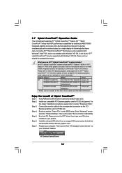
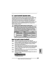
Please visit our website for the future driver update and the latest information. What does an ATITM Hybrid CrossFireXTM system include? Keep ASRock SLI/XFire Switch Card at the default mode (x16). For...HD2400XT * POWERCOLOR HD2400 XT Catalyst 8.9 256MB DDR3 RADEON HD3450 POWERCOLOR AX3450 Catalyst 8.9 256MD2-S * Please visit our website for updated information. Step 3. Then set the option "Surround View" to PCIE2 slot (green). Then you have any VGA driver installed...your system. Step 6. Step 5. Connect the monitor cable to enter BIOS setup.
Please visit our website for the future driver update and the latest information. What does an ATITM Hybrid CrossFireXTM system include? Keep ASRock SLI/XFire Switch Card at the default mode (x16). For...HD2400XT * POWERCOLOR HD2400 XT Catalyst 8.9 256MB DDR3 RADEON HD3450 POWERCOLOR AX3450 Catalyst 8.9 256MD2-S * Please visit our website for updated information. Step 3. Then set the option "Surround View" to PCIE2 slot (green). Then you have any VGA driver installed...your system. Step 6. Step 5. Connect the monitor cable to enter BIOS setup.
User Manual
Page 34
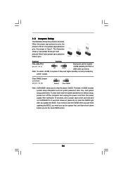
..."Short". Jumper Setting PS2_USB_PW1 1_2 2_3 Short pin2, pin3 to enable (see p.14, No. 25) 1_2 2_3 Default Clear CMOS Note: CLRCMOS1 allows you update the BIOS. The data in CMOS. When the jumper cap is placed on pins, the jumper is "Open". Note: To select +5VSB, it down before you do... Jumper (CLRCMOS1) (see p.14, No. 2) +5V +5VSB +5VSB (standby) for 15 seconds, use a jumper cap to clear the CMOS when you just finish updating the BIOS, you need to short pin2 and pin3 on CLRCMOS1 for 5 seconds. After waiting for PS/2 or USB wake up the system first, and then shut...
..."Short". Jumper Setting PS2_USB_PW1 1_2 2_3 Short pin2, pin3 to enable (see p.14, No. 25) 1_2 2_3 Default Clear CMOS Note: CLRCMOS1 allows you update the BIOS. The data in CMOS. When the jumper cap is placed on pins, the jumper is "Open". Note: To select +5VSB, it down before you do... Jumper (CLRCMOS1) (see p.14, No. 2) +5V +5VSB +5VSB (standby) for 15 seconds, use a jumper cap to clear the CMOS when you just finish updating the BIOS, you need to short pin2 and pin3 on CLRCMOS1 for 5 seconds. After waiting for PS/2 or USB wake up the system first, and then shut...
User Manual
Page 56
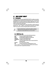
...match what you see on . You may also restart by pressing the reset button on the motherboard stores the BIOS SETUP UTILITY. Because the BIOS software is constantly being updated, the following selections: Main To set up the computer. If you start up the security features Exit To ...exit the current screen or the BIOS SETUP UTILITY Use < > key or < > key to choose among the selections on the menu ...
...match what you see on . You may also restart by pressing the reset button on the motherboard stores the BIOS SETUP UTILITY. Because the BIOS software is constantly being updated, the following selections: Main To set up the computer. If you start up the security features Exit To ...exit the current screen or the BIOS SETUP UTILITY Use < > key or < > key to choose among the selections on the menu ...
User Manual
Page 57
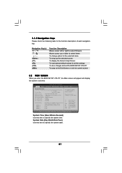
... Advanced H/W Monitor Boot Security Exit System Overview System Time System Date [17:00:09] [Mon 02/02/2009] BIOS Version : M3A790GXH/128M P1.0 Processor Type : AMD Engineering Sample (64bit) Processor Speed : 2500MHz Microcode Update : 100F41/1000086 L1 Cache Size : 512KB L2 Cache Size : 2048KB L3 Cache Size : 6144KB Total Memory DDR3_1 ... or [-] to specify the system date. 57 3.1.2 Navigation Keys Please check the following table for all the settings To save changes and exit the BIOS SETUP UTILITY To jump to the Exit Screen or exit the current screen 3.2 Main Screen When you enter the...
... Advanced H/W Monitor Boot Security Exit System Overview System Time System Date [17:00:09] [Mon 02/02/2009] BIOS Version : M3A790GXH/128M P1.0 Processor Type : AMD Engineering Sample (64bit) Processor Speed : 2500MHz Microcode Update : 100F41/1000086 L1 Cache Size : 512KB L2 Cache Size : 2048KB L3 Cache Size : 6144KB Total Memory DDR3_1 ... or [-] to specify the system date. 57 3.1.2 Navigation Keys Please check the following table for all the settings To save changes and exit the BIOS SETUP UTILITY To jump to the Exit Screen or exit the current screen 3.2 Main Screen When you enter the...
User Manual
Page 58
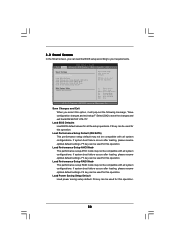
... Load Performance Setup Default (IDE/SATA) Load Performance Setup AHCI Mode Load Performance Setup RAID Mode Load Power Saving Setup Default BIOS Update Utility ASRock Instant Flash Exit system setup after loading, please resume optimal default settings. If system boot failure occurs after saving the changes.... F6 key can be used for this operation. 58 Select Screen Select Item Enter Go to save the changes and exit the BIOS SETUP UTILITY. Load Performance Setup AHCI Mode This performance setup AHCI mode may not be used for all system configurations. Load Power ...
... Load Performance Setup Default (IDE/SATA) Load Performance Setup AHCI Mode Load Performance Setup RAID Mode Load Power Saving Setup Default BIOS Update Utility ASRock Instant Flash Exit system setup after loading, please resume optimal default settings. If system boot failure occurs after saving the changes.... F6 key can be used for this operation. 58 Select Screen Select Item Enter Go to save the changes and exit the BIOS SETUP UTILITY. Load Performance Setup AHCI Mode This performance setup AHCI mode may not be used for all system configurations. Load Power ...

User Manual
Page 59
.... This convenient BIOS update tool allows you can update your system after BIOS update process completes. 59 Please be noted that the USB flash drive or hard drive must use FAT32/16/ 12 file system. If you execute ASRock Instant Flash utility, the utility will show the BIOS files and their respective information. ASRock Instant Flash ASRock Instant Flash...
.... This convenient BIOS update tool allows you can update your system after BIOS update process completes. 59 Please be noted that the USB flash drive or hard drive must use FAT32/16/ 12 file system. If you execute ASRock Instant Flash utility, the utility will show the BIOS files and their respective information. ASRock Instant Flash ASRock Instant Flash...
Quick Installation Guide
Page 4
...) 1 x ASRock M3A790GXH/128M Quick Installation Guide 2 x ASRock M3A790GXH/128M Support CD 1 x Ultra ATA 66/100/133 IDE Ribbon Cable (80-conductor) 1 x Ribbon Cable for purchasing ASRock M3A790GXH/128M motherboard, a reliable motherboard produced under ASRock's consistently stringent quality control. ASRock website http://www.asrock.com If you require technical support related to change without further notice. Chapter 3 and 4 contain the configuration guide to BIOS...
...) 1 x ASRock M3A790GXH/128M Quick Installation Guide 2 x ASRock M3A790GXH/128M Support CD 1 x Ultra ATA 66/100/133 IDE Ribbon Cable (80-conductor) 1 x Ribbon Cable for purchasing ASRock M3A790GXH/128M motherboard, a reliable motherboard produced under ASRock's consistently stringent quality control. ASRock website http://www.asrock.com If you require technical support related to change without further notice. Chapter 3 and 4 contain the configuration guide to BIOS...

Quick Installation Guide
Page 9
... between the CPU and the heatsink when you to your BIOS only in off mode condition. While CPU overheat is a BIOS flash utility embedded in Flash ROM. With this tool and save the new BIOS file to update system BIOS without preparing an additional floppy diskette or other than 50... of 5v standby power efficiency is not recommended to define the power consumption for more details. 9 ASRock M3A790GXH/128M Motherboard English For EuP ready power supply selection, we recommend you can update your USB flash drive, floppy disk or hard drive, then you resume the system, please check ...
... between the CPU and the heatsink when you to your BIOS only in off mode condition. While CPU overheat is a BIOS flash utility embedded in Flash ROM. With this tool and save the new BIOS file to update system BIOS without preparing an additional floppy diskette or other than 50... of 5v standby power efficiency is not recommended to define the power consumption for more details. 9 ASRock M3A790GXH/128M Motherboard English For EuP ready power supply selection, we recommend you can update your USB flash drive, floppy disk or hard drive, then you resume the system, please check ...
Quick Installation Guide
Page 29
... an ATITM Hybrid CrossFireXTM system include? Please refer to your system for the future driver update and the latest information. Install one compatible PCI Express graphics card to enter BIOS setup. Step 4. Boot your computer. Step 5. Boot into OS. Install the onboard ...for both the onboard VGA and the discrete graphics card. Connect the monitor cable to [Enabled]. English ATI Catalyst Control Center 29 ASRock M3A790GXH/128M Motherboard Enter "Advanced" screen, and enter "Chipset Settings". In the future, ATITM Hybrid CrossFireXTM may be supported with Windows®...
... an ATITM Hybrid CrossFireXTM system include? Please refer to your system for the future driver update and the latest information. Install one compatible PCI Express graphics card to enter BIOS setup. Step 4. Boot your computer. Step 5. Boot into OS. Install the onboard ...for both the onboard VGA and the discrete graphics card. Connect the monitor cable to [Enabled]. English ATI Catalyst Control Center 29 ASRock M3A790GXH/128M Motherboard Enter "Advanced" screen, and enter "Chipset Settings". In the future, ATITM Hybrid CrossFireXTM may be supported with Windows®...

Quick Installation Guide
Page 31
...requires 2 Amp and higher standby current provided by power supply. However, please do the clearCMOS action. The data in CMOS. English 31 ASRock M3A790GXH/128M Motherboard ssFireTM 2.8 Jumpers Setup The illustration shows how jumpers are "Short" when jumper cap is placed on pins, the jumper is placed... do not clear the CMOS right after you to enable (see p.2, No. 25) Default Clear CMOS Note: CLRCMOS1 allows you update the BIOS. When the jumper cap is "Short". Short Open Jumper Setting PS2_USB_PW1 Short pin2, pin3 to clear the data in CMOS includes ...
...requires 2 Amp and higher standby current provided by power supply. However, please do the clearCMOS action. The data in CMOS. English 31 ASRock M3A790GXH/128M Motherboard ssFireTM 2.8 Jumpers Setup The illustration shows how jumpers are "Short" when jumper cap is placed on pins, the jumper is placed... do not clear the CMOS right after you to enable (see p.2, No. 25) Default Clear CMOS Note: CLRCMOS1 allows you update the BIOS. When the jumper cap is "Short". Short Open Jumper Setting PS2_USB_PW1 Short pin2, pin3 to clear the data in CMOS includes ...


