
User Manual
Page 5
... 1.2 Specifications 2 1.3 Motherboard Layout 6 1.4 I/O Panel 8 1.5 WiFi-802.11ac Module and ASRock WiFi 2.4/5 GHz Antennas 10 Chapter 2 Installation 12 2.1 Installing the CPU 13 2.2 Installing the CPU Fan and Heatsink 16 2.3 Installing Memory Modules (DIMM) 17 2.4 Expansion Slots (PCI Express Slot) 19 2.5 Jumpers Setup 20 2.6 Onboard Headers and Connectors 21 2.7 M.2_SSD (NGFF) Module Installation Guide 26 Chapter 3 Software and Utilities Operation 30 3.1 Installing Drivers 30 3.2 ASRock Motherboard Utility (A-Tuning) 31 3.2.1 Installing ASRock Motherboard Utility...
... 1.2 Specifications 2 1.3 Motherboard Layout 6 1.4 I/O Panel 8 1.5 WiFi-802.11ac Module and ASRock WiFi 2.4/5 GHz Antennas 10 Chapter 2 Installation 12 2.1 Installing the CPU 13 2.2 Installing the CPU Fan and Heatsink 16 2.3 Installing Memory Modules (DIMM) 17 2.4 Expansion Slots (PCI Express Slot) 19 2.5 Jumpers Setup 20 2.6 Onboard Headers and Connectors 21 2.7 M.2_SSD (NGFF) Module Installation Guide 26 Chapter 3 Software and Utilities Operation 30 3.1 Installing Drivers 30 3.2 ASRock Motherboard Utility (A-Tuning) 31 3.2.1 Installing ASRock Motherboard Utility...
User Manual
Page 7
... BIOS setup. H410M-ITX/ac Chapter 1 Introduction Thank you are using. In this documentation occur, the updated version will be updated, the content of the motherboard and step-by-step installation guides. In case any modifications of this documentation, Chapter 1 and 2 contains the introduction of this motherboard, please visit our website for specific information about the model you for M.2 Socket (Optional) 1 English You may find the latest VGA cards and CPU support list...
... BIOS setup. H410M-ITX/ac Chapter 1 Introduction Thank you are using. In this documentation occur, the updated version will be updated, the content of the motherboard and step-by-step installation guides. In case any modifications of this documentation, Chapter 1 and 2 contains the introduction of this motherboard, please visit our website for specific information about the model you for M.2 Socket (Optional) 1 English You may find the latest VGA cards and CPU support list...

User Manual
Page 9
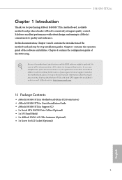
... (High Bit Rate Audio) with HDMI 1.4 Port (Compliant HDMI monitor is required) • Supports HDCP 2.3 with HDMI 1.4 and DisplayPort 1.4 Ports • Supports 4K Ultra HD (UHD) playback with max. H410M-ITX/ac Audio LAN Wireless LAN * VP9 10bit and VC-1 are for decode only. * VP8 and VP9 encode are not supported by Windows OS. • Graphics, Media & Compute: Microsoft DirectX 12, OpenGL 4.5, Intel® Built In Visuals, Intel® Quick Sync Video...
... (High Bit Rate Audio) with HDMI 1.4 Port (Compliant HDMI monitor is required) • Supports HDCP 2.3 with HDMI 1.4 and DisplayPort 1.4 Ports • Supports 4K Ultra HD (UHD) playback with max. H410M-ITX/ac Audio LAN Wireless LAN * VP9 10bit and VC-1 are for decode only. * VP8 and VP9 encode are not supported by Windows OS. • Graphics, Media & Compute: Microsoft DirectX 12, OpenGL 4.5, Intel® Built In Visuals, Intel® Quick Sync Video...

User Manual
Page 10
...-45 LAN Port with LED (ACT/LINK LED and SPEED LED) • HD Audio Jacks: Line in / Front Speaker / Microphone Storage • 4 x SATA3 6.0 Gb/s Connectors, support NCQ, AHCI and Hot Plug* * If M2_1 is occupied by a SATA-type M.2 device, SATA3_0 will be disabled. • 1 x Ultra M.2 Socket (M2_1), supports M Key type 2280 M.2 SATA3 6.0 Gb/s module and M.2 PCI Express module up to Gen3 x4 (32 Gb/s)** ** Supports NVMe SSD as boot disks ** Supports ASRock U.2 Kit Connector • 1 x Chassis Intrusion Header • 1 x RGB LED Header * Support in...
...-45 LAN Port with LED (ACT/LINK LED and SPEED LED) • HD Audio Jacks: Line in / Front Speaker / Microphone Storage • 4 x SATA3 6.0 Gb/s Connectors, support NCQ, AHCI and Hot Plug* * If M2_1 is occupied by a SATA-type M.2 device, SATA3_0 will be disabled. • 1 x Ultra M.2 Socket (M2_1), supports M Key type 2280 M.2 SATA3 6.0 Gb/s module and M.2 PCI Express module up to Gen3 x4 (32 Gb/s)** ** Supports NVMe SSD as boot disks ** Supports ASRock U.2 Kit Connector • 1 x Chassis Intrusion Header • 1 x RGB LED Header * Support in...
User Manual
Page 11
... for possible damage caused by CPU tempera- English 5 Overclocking may affect your system's stability, or even cause damage to the components and devices of your own risk and expense. H410M-ITX/ac • 1 x USB 2.0 Header (Supports 2 USB 2.0 ports) (Supports ESD Protection) • 1 x USB 3.2 Gen1 Header (Supports 2 USB 3.2 Gen1 ports) (Supports ESD Protection) BIOS Feature • AMI UEFI Legal BIOS with overclocking, including adjusting the setting in the BIOS, applying Untied Overclocking Technology, or using third-party overclocking tools.
... for possible damage caused by CPU tempera- English 5 Overclocking may affect your system's stability, or even cause damage to the components and devices of your own risk and expense. H410M-ITX/ac • 1 x USB 2.0 Header (Supports 2 USB 2.0 ports) (Supports ESD Protection) • 1 x USB 3.2 Gen1 Header (Supports 2 USB 3.2 Gen1 ports) (Supports ESD Protection) BIOS Feature • AMI UEFI Legal BIOS with overclocking, including adjusting the setting in the BIOS, applying Untied Overclocking Technology, or using third-party overclocking tools.

User Manual
Page 13
...) 3 Chassis/Waterpump Fan Connector (CHA_FAN1/WP) 4 RGB LED Header (RGB_LED1) 5 Addressable LED Header (ADDR_LED1) 6 2 x 288-pin DDR4 DIMM Slots (DDR4_A1, DDR4_B1) 7 ATX Power Connector (ATXPWR1) 8 Chassis Fan Connector (CHA_FAN2) 9 USB 3.2 Gen1 Header (USB3_3_4) 10 SATA3 Connector (SATA3_1) 11 SATA3 Connector (SATA3_0) 12 SATA3 Connector (SATA3_3) 13 SATA3 Connector (SATA3_2) 14 System Panel Header (PANEL1) 15 USB 2.0 Header (USB_3_4) 16 Clear CMOS Jumper (CLRMOS1) 17 Chassis Speaker Header (SPEAKER1) 18 Chassis Intrusion Header (CI1) 19 Front Panel Audio Header (HD_AUDIO1) H410M-ITX/ac...
...) 3 Chassis/Waterpump Fan Connector (CHA_FAN1/WP) 4 RGB LED Header (RGB_LED1) 5 Addressable LED Header (ADDR_LED1) 6 2 x 288-pin DDR4 DIMM Slots (DDR4_A1, DDR4_B1) 7 ATX Power Connector (ATXPWR1) 8 Chassis Fan Connector (CHA_FAN2) 9 USB 3.2 Gen1 Header (USB3_3_4) 10 SATA3 Connector (SATA3_1) 11 SATA3 Connector (SATA3_0) 12 SATA3 Connector (SATA3_3) 13 SATA3 Connector (SATA3_2) 14 System Panel Header (PANEL1) 15 USB 2.0 Header (USB_3_4) 16 Clear CMOS Jumper (CLRMOS1) 17 Chassis Speaker Header (SPEAKER1) 18 Chassis Intrusion Header (CI1) 19 Front Panel Audio Header (HD_AUDIO1) H410M-ITX/ac...

User Manual
Page 23
... slot; H410M-ITX/ac 2.3 Installing Memory Modules (DIMM) This motherboard provides two 288-pin DDR4 (Double Data Rate 4) DIMM slots, and supports Dual Channel Memory Technology. 1. It will cause permanent damage to the motherboard and the DIMM if you always need to install a DDR, DDR2 or DDR3 memory module into the slot at incorrect orientation. 17 English It is not allowed to install identical (the same brand, speed, size and chip-type) DDR4...
... slot; H410M-ITX/ac 2.3 Installing Memory Modules (DIMM) This motherboard provides two 288-pin DDR4 (Double Data Rate 4) DIMM slots, and supports Dual Channel Memory Technology. 1. It will cause permanent damage to the motherboard and the DIMM if you always need to install a DDR, DDR2 or DDR3 memory module into the slot at incorrect orientation. 17 English It is not allowed to install identical (the same brand, speed, size and chip-type) DDR4...

User Manual
Page 25
H410M-ITX/ac 2.4 Expansion Slots (PCI Express Slot) There is unplugged. PCIe slot: PCIE1 (PCIe 3.0 x16 slot) is used for the card before you start the installation. Before installing an expansion card, please make necessary hardware settings for PCI Express x16 lane width graphics cards. 19 English Please read the documentation of the expansion card and make sure that the power supply is switched off or the power cord is 1 PCI Express slot slot on the motherboard.
H410M-ITX/ac 2.4 Expansion Slots (PCI Express Slot) There is unplugged. PCIe slot: PCIE1 (PCIe 3.0 x16 slot) is used for the card before you start the installation. Before installing an expansion card, please make necessary hardware settings for PCI Express x16 lane width graphics cards. 19 English Please read the documentation of the expansion card and make sure that the power supply is switched off or the power cord is 1 PCI Express slot slot on the motherboard.

User Manual
Page 26
... seconds, use a jumper cap to default setup, please turn off the computer and unplug the power cord from the power supply. English 20 2.5 Jumpers Setup The illustration shows how jumpers are setup. However, please do the clear-CMOS action. To clear and reset the system parameters to short the pins on the pins, the jumper is "Short". Please adjust the BIOS option "Clear Status" to clear the data in CMOS. Please remember toremove the jumper cap after...
... seconds, use a jumper cap to default setup, please turn off the computer and unplug the power cord from the power supply. English 20 2.5 Jumpers Setup The illustration shows how jumpers are setup. However, please do the clear-CMOS action. To clear and reset the system parameters to short the pins on the pins, the jumper is "Short". Please adjust the BIOS option "Clear Status" to clear the data in CMOS. Please remember toremove the jumper cap after...

User Manual
Page 27
... headers and connectors will cause permanent damage to the reset switch on the chassis front panel. English 21 The LED is on when the hard drive is in S4 sleep state or powered off your chassis front panel module to the hard drive activity LED on the chassis front panel. Note the positive and negative pins before connecting the cables. PLED (System Power LED): Connect to the power status indicator on the chassis front panel. H410M-ITX/ac 2.6 Onboard Headers and Connectors Onboard headers and connectors...
... headers and connectors will cause permanent damage to the reset switch on the chassis front panel. English 21 The LED is on when the hard drive is in S4 sleep state or powered off your chassis front panel module to the hard drive activity LED on the chassis front panel. Note the positive and negative pins before connecting the cables. PLED (System Power LED): Connect to the power status indicator on the chassis front panel. H410M-ITX/ac 2.6 Onboard Headers and Connectors Onboard headers and connectors...

User Manual
Page 29
... (Hard Drive Activity LED): Connect to the hard drive activity LED on the chassis front panel. If you plan to connect a 3-Pin chassis water cooler fan, please connect it to perform a normal restart. Chassis Fan Connector 1 (4-pin CHA_FAN2) 2 3 (see p.6, No. 8) 4 GND +12V CHA_FAN_SPEED FAN_SPEED_CONTROL Please connect fan cables to the fan connector and match the black wire to the ground pin. The front panel design may configure the way to turn off (S5). H410M-ITX/ac PWRBTN (Power Switch): Connect to the power switch on the chassis...
... (Hard Drive Activity LED): Connect to the hard drive activity LED on the chassis front panel. If you plan to connect a 3-Pin chassis water cooler fan, please connect it to perform a normal restart. Chassis Fan Connector 1 (4-pin CHA_FAN2) 2 3 (see p.6, No. 8) 4 GND +12V CHA_FAN_SPEED FAN_SPEED_CONTROL Please connect fan cables to the fan connector and match the black wire to the ground pin. The front panel design may configure the way to turn off (S5). H410M-ITX/ac PWRBTN (Power Switch): Connect to the power switch on the chassis...

User Manual
Page 30
...power connector. 1 13 ATX 12V Power Connector (8-pin ATX12V1) (see p.6, No. 1) RGB LED Header (4-pin RGB_LED1) (see p.6, No. 2) FAN_SPEED This motherboard pro- Do not plug the PCIe power cable to choose from various LED lighting effects. Caution: Never install the RGB LED cable in the wrong orientation; To use a 4-pin ATX power supply, please plug it to page 40 for the CPU and not the graphics card. English FAN_VOLTAGE_CONTROL GND FAN_SPEED_CONTROL vides a 4-Pin CPU fan (Quiet Fan) connector. RGB header is for further instructions on this connector. CPU Fan Connector (4-pin...
...power connector. 1 13 ATX 12V Power Connector (8-pin ATX12V1) (see p.6, No. 1) RGB LED Header (4-pin RGB_LED1) (see p.6, No. 2) FAN_SPEED This motherboard pro- Do not plug the PCIe power cable to choose from various LED lighting effects. Caution: Never install the RGB LED cable in the wrong orientation; To use a 4-pin ATX power supply, please plug it to page 40 for the CPU and not the graphics card. English FAN_VOLTAGE_CONTROL GND FAN_SPEED_CONTROL vides a 4-Pin CPU fan (Quiet Fan) connector. RGB header is for further instructions on this connector. CPU Fan Connector (4-pin...

User Manual
Page 31
... motherboard supports CASE OPEN detection feature that detects if the chassis cove has been removed. otherwise, the cable may be damaged. * Please refer to choose from various LED lighting effects. Caution: Never install the Addressable LED cable in the wrong orientation; H410M-ITX/ac Addressable LED Header (3-pin ADDR_LED1) (see p.6, No. 5) Chassis Intrusion Header (2-pin CI1) (see p.6, No. 18) 1 GND DO_ADDR VOUT 1 GND Signal This header is used to connect Addressable LED extension cable which...
... motherboard supports CASE OPEN detection feature that detects if the chassis cove has been removed. otherwise, the cable may be damaged. * Please refer to choose from various LED lighting effects. Caution: Never install the Addressable LED cable in the wrong orientation; H410M-ITX/ac Addressable LED Header (3-pin ADDR_LED1) (see p.6, No. 5) Chassis Intrusion Header (2-pin CI1) (see p.6, No. 18) 1 GND DO_ADDR VOUT 1 GND Signal This header is used to connect Addressable LED extension cable which...
User Manual
Page 36
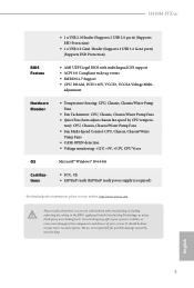
... with the motherboard contains necessary drivers and useful utilities that the motherboard supports. Please click Install All or follow the installation wizard to display the menu. The CD automatically displays the Main Menu if "AUTORUN" is enabled in the Support CD to install it. 30 English Therefore, the drivers you install can work properly. Drivers Menu The drivers compatible to your system will be auto-detected and listed on the file "ASRSETUP.EXE" in your CD-ROM drive.
... with the motherboard contains necessary drivers and useful utilities that the motherboard supports. Please click Install All or follow the installation wizard to display the menu. The CD automatically displays the Main Menu if "AUTORUN" is enabled in the Support CD to install it. 30 English Therefore, the drivers you install can work properly. Drivers Menu The drivers compatible to your system will be auto-detected and listed on the file "ASRSETUP.EXE" in your CD-ROM drive.

User Manual
Page 55
... DRAM Timing Configuration Load XMP Setting Load XMP settings to switch between multiple frequencies and voltage points for processors that the BIOS will detect the memory module(s) inserted and assign the appropriate frequency automatically. 49 English Intel SpeedStep Technology Intel SpeedStep technology allows processors to overclock the memory and perform beyond standard specifications. Intel Thermal Velocity Boost Voltage Optimizations This service controls thermal based voltage optimizations for better power saving and heat dissipation. H410M-ITX/ac Boot Performance Mode...
... DRAM Timing Configuration Load XMP Setting Load XMP settings to switch between multiple frequencies and voltage points for processors that the BIOS will detect the memory module(s) inserted and assign the appropriate frequency automatically. 49 English Intel SpeedStep Technology Intel SpeedStep technology allows processors to overclock the memory and perform beyond standard specifications. Intel Thermal Velocity Boost Voltage Optimizations This service controls thermal based voltage optimizations for better power saving and heat dissipation. H410M-ITX/ac Boot Performance Mode...

User Manual
Page 65
...® Virtualization Technology for overclocking. SR-IOV Support If system has SR-IOV capable PCIe Devices, this option Enables or Disables Single Root IO Virtualization Support. Auto mode is optimizing for Directed I/O helps your virtual machine monitor better utilize hardware by improving application compatibility and reliability, and providing additional levels of manageability, security, isolation, and I/O performance. DMI Link Speed Configure DMI Slot Link Speed. Above 4G Decoding Enable or disable 64bit capable Devices to...
...® Virtualization Technology for overclocking. SR-IOV Support If system has SR-IOV capable PCIe Devices, this option Enables or Disables Single Root IO Virtualization Support. Auto mode is optimizing for Directed I/O helps your virtual machine monitor better utilize hardware by improving application compatibility and reliability, and providing additional levels of manageability, security, isolation, and I/O performance. DMI Link Speed Configure DMI Slot Link Speed. Above 4G Decoding Enable or disable 64bit capable Devices to...

User Manual
Page 66
...Share Memory Configure the size of the DMI Link. Set to Auto to enable onboard HD audio and automatically disable it when a sound card is allocated to disable the integrated graphics when an external graphics card is installed. Front Panel Enable/disable front panel HD audio. Onboard HD Audio Enable/disable onboard HD audio. PCH PCIE ASPM Support This option enables/disables the ASPM support for enhanced PCI Express power saving in OS. IGPU Multi-Monitor Select disable to the integrated graphics processor when the system boots up. PCIE ASPM Support This option enables/disables...
...Share Memory Configure the size of the DMI Link. Set to Auto to enable onboard HD audio and automatically disable it when a sound card is allocated to disable the integrated graphics when an external graphics card is installed. Front Panel Enable/disable front panel HD audio. Onboard HD Audio Enable/disable onboard HD audio. PCH PCIE ASPM Support This option enables/disables the ASPM support for enhanced PCI Express power saving in OS. IGPU Multi-Monitor Select disable to the integrated graphics processor when the system boots up. PCIE ASPM Support This option enables/disables...

User Manual
Page 71
The XHCI ownership change should be claimed by XHCI driver. 65 English Select UEFI Setup Only to disable legacy USB support. 4.6.6 USB Configuration H410M-ITX/ac Legacy USB Support Enable or disable Legacy OS Support for OSes without XHCI hand-off This is recommended to support USB devices under the UEFI setup and Windows/Linux operating systems only. XHCI Hand-off support. If you encounter USB compatibility issues it is a workaround for USB 2.0 devices.
The XHCI ownership change should be claimed by XHCI driver. 65 English Select UEFI Setup Only to disable legacy USB support. 4.6.6 USB Configuration H410M-ITX/ac Legacy USB Support Enable or disable Legacy OS Support for OSes without XHCI hand-off This is recommended to support USB devices under the UEFI setup and Windows/Linux operating systems only. XHCI Hand-off support. If you encounter USB compatibility issues it is a workaround for USB 2.0 devices.
User Manual
Page 74
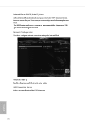
Internet Setting Enable or disable sound effects in your USB pen drive before using this to download the UEFI firmware. 68 English UEFI Download Server Select a server to configure internet connection settings for you. Network Configuration Use this function. Please setup network configuration before using Internet Flash. *For BIOS backup and recovery purpose, it is recommended to plug in the setup utility. DHCP (Auto IP), Auto ASRock Internet Flash downloads and updates the latest UEFI firmware version from our servers for Internet Flash. Internet Flash -
Internet Setting Enable or disable sound effects in your USB pen drive before using this to download the UEFI firmware. 68 English UEFI Download Server Select a server to configure internet connection settings for you. Network Configuration Use this function. Please setup network configuration before using Internet Flash. *For BIOS backup and recovery purpose, it is recommended to plug in the setup utility. DHCP (Auto IP), Auto ASRock Internet Flash downloads and updates the latest UEFI firmware version from our servers for Internet Flash. Internet Flash -

User Manual
Page 77
H410M-ITX/ac 4.9 Security Screen In this section you may also clear the user password. Leave it blank and press enter to change the settings in ME. Users are unable to remove the password. Disable this item to use discrete TPM Module. 71 English You may set or change the password for the user account. Supervisor Password Set or change the supervisor/user password for Secure Boot. Secure Boot Use this option to enable or disable support for the system. Intel(R) Platform...
H410M-ITX/ac 4.9 Security Screen In this section you may also clear the user password. Leave it blank and press enter to change the settings in ME. Users are unable to remove the password. Disable this item to use discrete TPM Module. 71 English You may set or change the password for the user account. Supervisor Password Set or change the supervisor/user password for Secure Boot. Secure Boot Use this option to enable or disable support for the system. Intel(R) Platform...


