User Manual
Page 3
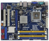
Contents 1 Introduction 5 1.1 Package Contents 5 1.2 Specifications 6 1.3 Motherboard Layout (G41C-GS / G41C-S 11 1.4 I/O Panel (G41C-GS 12 1.5 I/O Panel (G41C-S 13 2 Installation 14 2.1 Screw Holes 14 2.2 Pre-installation Precautions 14 2.3 CPU Installation 15 2.4 Installation of ...and Connectors 22 2.9 SATAII Hard Disk Setup Guide 25 2.10 Serial ATA (SATA) / Serial ATAII (SATAII) Hard Disks Installation 26 2.11 Driver Installation Guide 26 2.12 Untied Overclocking Technology 26 3 BIOS SETUP UTILITY 27 3.1 Introduction 27 3.1.1 BIOS Menu Bar 27 3.1.2 Navigation Keys 28 ...
Contents 1 Introduction 5 1.1 Package Contents 5 1.2 Specifications 6 1.3 Motherboard Layout (G41C-GS / G41C-S 11 1.4 I/O Panel (G41C-GS 12 1.5 I/O Panel (G41C-S 13 2 Installation 14 2.1 Screw Holes 14 2.2 Pre-installation Precautions 14 2.3 CPU Installation 15 2.4 Installation of ...and Connectors 22 2.9 SATAII Hard Disk Setup Guide 25 2.10 Serial ATA (SATA) / Serial ATAII (SATAII) Hard Disks Installation 26 2.11 Driver Installation Guide 26 2.12 Untied Overclocking Technology 26 3 BIOS SETUP UTILITY 27 3.1 Introduction 27 3.1.1 BIOS Menu Bar 27 3.1.2 Navigation Keys 28 ...

User Manual
Page 4
3.7 Security Screen 51 3.8 Exit Screen 52 4 Software Support 53 4.1 Install Operating System 53 4.2 Support CD Information 53 4.2.1 Running Support CD 53 4.2.2 Drivers Menu 53 4.2.3 Utilities Menu 53 4.2.4 Contact Information 53 4
3.7 Security Screen 51 3.8 Exit Screen 52 4 Software Support 53 4.1 Install Operating System 53 4.2 Support CD Information 53 4.2.1 Running Support CD 53 4.2.2 Drivers Menu 53 4.2.3 Utilities Menu 53 4.2.4 Contact Information 53 4

User Manual
Page 7
... (B.F.G.) - Chassis Temperature Sensing - ASRock OC DNA (see CAUTION 9) - ASRock U-COP (see CAUTION 8) - 8Mb AMI BIOS - Supports "Plug and Play" - ACPI 1.1 Compliance Wake Up Events - Drivers, Utilities, AntiVirus Software (Trial Version), ASRock Software Suite (CyberLink DVD Suite and... FAN connector - 24 pin ATX power connector - 4 pin 12V power connector - VCCM, NB, VTT, GTLRef Voltage Multi-adjustment - Supports Smart BIOS - ASRock Instant Flash (see CAUTION 7) - 1 x ATA100 IDE connector (supports 2 x IDE devices) - 1 x Floppy connector - 1 x Print port header ...
... (B.F.G.) - Chassis Temperature Sensing - ASRock OC DNA (see CAUTION 9) - ASRock U-COP (see CAUTION 8) - 8Mb AMI BIOS - Supports "Plug and Play" - ACPI 1.1 Compliance Wake Up Events - Drivers, Utilities, AntiVirus Software (Trial Version), ASRock Software Suite (CyberLink DVD Suite and... FAN connector - 24 pin ATX power connector - 4 pin 12V power connector - VCCM, NB, VTT, GTLRef Voltage Multi-adjustment - Supports Smart BIOS - ASRock Instant Flash (see CAUTION 7) - 1 x ATA100 IDE connector (supports 2 x IDE devices) - 1 x Floppy connector - 1 x Print port header ...
User Manual
Page 26
...warning on this motherboard for the possible overclocking risk before you to your optical drive first. Please refer to install those required drivers. Then, the drivers compatible to [Manual]. Before you install can work properly. 2 . 1 2 Untied Overclocking Technology This motherboard supports Untied ... for internal storage devices. STEP 3: Connect one end of the SATA data cable to the SATA / SATAII hard disk. 2.11 Driver Installation Guide To install the drivers to your system, please insert the support CD to install the SATA / SATAII hard disks. 2 . 1 0 Serial ATA (...
...warning on this motherboard for the possible overclocking risk before you to your optical drive first. Please refer to install those required drivers. Then, the drivers compatible to [Manual]. Before you install can work properly. 2 . 1 2 Untied Overclocking Technology This motherboard supports Untied ... for internal storage devices. STEP 3: Connect one end of the SATA data cable to the SATA / SATAII hard disk. 2.11 Driver Installation Guide To install the drivers to your system, please insert the support CD to install the SATA / SATAII hard disks. 2 . 1 0 Serial ATA (...

User Manual
Page 41
...motherboard through efficient memory utilization. Share Memory This allows you to enable or disable flex mode operation feature. In DVMT mode, the graphics driver allocates memory as needed for running graphics applications and is hardware-based 128-bit AES decryption. The option [Maximum DVMT] only appears ... 1024MB or above. Configuration options: [Enabled] and [Disabled]. This item will not be used under Windows® VistaTM OS because the driver will be disabled when PCI Sound Card is [PCI]. Flex Mode Operation This allows you to set DVMT Mode Select as the boot graphic...
...motherboard through efficient memory utilization. Share Memory This allows you to enable or disable flex mode operation feature. In DVMT mode, the graphics driver allocates memory as needed for running graphics applications and is hardware-based 128-bit AES decryption. The option [Maximum DVMT] only appears ... 1024MB or above. Configuration options: [Enabled] and [Disabled]. This item will not be used under Windows® VistaTM OS because the driver will be disabled when PCI Sound Card is [PCI]. Flex Mode Operation This allows you to set DVMT Mode Select as the boot graphic...
User Manual
Page 53
or you need to contact ASRock or want to know more information. 4.2 Support CD Information The Support CD that came with the motherboard contains necessary drivers and useful utilities that the motherboard supports. The CD automatically displays the Main Menu if "AUTORUN" is enabled ... display the menus. 4.2.2 Drivers Menu The Drivers Menu shows the available devices drivers if the system detects installed devices. Click on the file "ASSETUP.EXE" from the BIN folder in this chapter for more about ASRock, welcome to your CD-ROM drive. Chapter 4 Software Support 4.1 Install ...
or you need to contact ASRock or want to know more information. 4.2 Support CD Information The Support CD that came with the motherboard contains necessary drivers and useful utilities that the motherboard supports. The CD automatically displays the Main Menu if "AUTORUN" is enabled ... display the menus. 4.2.2 Drivers Menu The Drivers Menu shows the available devices drivers if the system detects installed devices. Click on the file "ASSETUP.EXE" from the BIN folder in this chapter for more about ASRock, welcome to your CD-ROM drive. Chapter 4 Software Support 4.1 Install ...
Quick Installation Guide
Page 7
...12V power connector - Drivers, Utilities, AntiVirus Software (Trial Version), ASRock Software Suite (CyberLink DVD Suite and Creative Sound Blaster X-Fi MB) (OEM and Trial Version) Unique Feature - Instant Boot - Supports Smart BIOS Support CD - ASRock Instant Flash (see... +3.3V, Vcore OS - Microsoft® Windows® 7 / 7 64-bit / VistaTM / VistaTM 64-bit / XP / XP 64-bit compliant 7 ASRock G41C-GS / G41C-S Motherboard VCCM, NB, VTT, GTLRef Voltage Multi-adjustment - Intelligent Energy Saver (see CAUTION 11) Hardware Monitor - CPU Quiet Fan - - 1 x Serial...
...12V power connector - Drivers, Utilities, AntiVirus Software (Trial Version), ASRock Software Suite (CyberLink DVD Suite and Creative Sound Blaster X-Fi MB) (OEM and Trial Version) Unique Feature - Instant Boot - Supports Smart BIOS Support CD - ASRock Instant Flash (see... +3.3V, Vcore OS - Microsoft® Windows® 7 / 7 64-bit / VistaTM / VistaTM 64-bit / XP / XP 64-bit compliant 7 ASRock G41C-GS / G41C-S Motherboard VCCM, NB, VTT, GTLRef Voltage Multi-adjustment - Intelligent Energy Saver (see CAUTION 11) Hardware Monitor - CPU Quiet Fan - - 1 x Serial...
Quick Installation Guide
Page 21
... data cable to the SATA / SATAII hard disk. Then, the drivers compatible to your system can be auto-detected and listed on page 8 for internal storage devices. Please refer to your chassis. English 21 ASRock G41C-GS / G41C-S Motherboard STEP 3: Connect one end of your optical drive first. ... option of the SATA data cable to the SATA / SATAII hard disk. 2.8 Driver Installation Guide To install the drivers to your system, please insert the support CD to the warning on the support CD driver page. Please follow the order from [Auto] to install the SATA / SATAII hard...
... data cable to the SATA / SATAII hard disk. Then, the drivers compatible to your system can be auto-detected and listed on page 8 for internal storage devices. Please refer to your chassis. English 21 ASRock G41C-GS / G41C-S Motherboard STEP 3: Connect one end of your optical drive first. ... option of the SATA data cable to the SATA / SATAII hard disk. 2.8 Driver Installation Guide To install the drivers to your system, please insert the support CD to the warning on the support CD driver page. Please follow the order from [Auto] to install the SATA / SATAII hard...
Quick Installation Guide
Page 22
...CD into your computer. 3. BIOS Information The Flash Memory on the system chassis. If you wish to display the menus. 22 ASRock G41C-GS / G41C-S Motherboard English The BIOS Setup program is a menu-driven program, which allows you start up the computer, please press during the ...Power-On-Self-Test (POST) to be user-friendly. It is designed to enter BIOS Setup utility; otherwise, POST continues with the motherboard contains necessary drivers...
...CD into your computer. 3. BIOS Information The Flash Memory on the system chassis. If you wish to display the menus. 22 ASRock G41C-GS / G41C-S Motherboard English The BIOS Setup program is a menu-driven program, which allows you start up the computer, please press during the ...Power-On-Self-Test (POST) to be user-friendly. It is designed to enter BIOS Setup utility; otherwise, POST continues with the motherboard contains necessary drivers...


