User Manual
Page 3
... of Memory Modules (DIMM 18 2.6 Expansion Slots (PCI and PCI Express Slots 20 2.7 Jumpers Setup 21 2.8 Onboard Headers and Connectors 22 2.9 SATAII Hard Disk Setup Guide 25 2.10 Serial ATA (SATA) / Serial ATAII (SATAII) Hard Disks Installation 26 2.11 Driver Installation Guide 26 2.12 Untied Overclocking Technology 26 3 BIOS SETUP UTILITY 27 3.1 Introduction 27 3.1.1 BIOS Menu Bar 27 3.1.2 Navigation Keys 28 3.2 Main Screen 28 3.3 OC Tweaker Screen 30 3.4 Advanced Screen 34 3.4.1 CPU Configuration 35 3.4.2 Chipset Configuration 37 3.4.3 ACPI Configuration 42 3.4.4 Storage...
... of Memory Modules (DIMM 18 2.6 Expansion Slots (PCI and PCI Express Slots 20 2.7 Jumpers Setup 21 2.8 Onboard Headers and Connectors 22 2.9 SATAII Hard Disk Setup Guide 25 2.10 Serial ATA (SATA) / Serial ATAII (SATAII) Hard Disks Installation 26 2.11 Driver Installation Guide 26 2.12 Untied Overclocking Technology 26 3 BIOS SETUP UTILITY 27 3.1 Introduction 27 3.1.1 BIOS Menu Bar 27 3.1.2 Navigation Keys 28 3.2 Main Screen 28 3.3 OC Tweaker Screen 30 3.4 Advanced Screen 34 3.4.1 CPU Configuration 35 3.4.2 Chipset Configuration 37 3.4.3 ACPI Configuration 42 3.4.4 Storage...
User Manual
Page 9
... save the new BIOS file to your USB flash drive, floppy disk or hard drive, then you can update your hardware devices to access ASRock Instant Flash. Please be shared and worked on the motherboard functions properly and unplug the power cord, then plug it is able to perform over-clocking. With OC DNA, you can save your system by ASRock, provides a convenient way for USB 2.0 works fine under Windows® environment. Your...
... save the new BIOS file to your USB flash drive, floppy disk or hard drive, then you can update your hardware devices to access ASRock Instant Flash. Please be shared and worked on the motherboard functions properly and unplug the power cord, then plug it is able to perform over-clocking. With OC DNA, you can save your system by ASRock, provides a convenient way for USB 2.0 works fine under Windows® environment. Your...
User Manual
Page 11
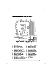
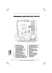
...12V Connector (ATX12V2) 17 USB 2.0 Header (USB6_7, Blue) 3 CPU Fan Connector (CPU_FAN1) 18 USB 2.0 Header (USB4_5, Blue) 4 ATX Power Connector (ATXPWR1) 19 System Panel Header (PANEL1, Orange) 5 2 x 240-pin DDR2 DIMM Slots 20 BIOS SPI Chip (Dual Channel: DDRII_1, DDRII_2; Red) (HD_AUDIO1, Lime) 14 Chassis Speaker Header (SPEAKER 1, Purple) 30 775-Pin CPU Socket 15 Secondary SATAII Connector (SATAII_2; Yellow) 21 Floppy Connector (FLOPPY1) 6 2 x 240-pin DDR3 DIMM Slots 22 Print Port Header (LPT1, Purple) (Dual Channel: DDR3_A1, DDR3_B1; 1.3 Motherboard Layout (G41C-GS...
...12V Connector (ATX12V2) 17 USB 2.0 Header (USB6_7, Blue) 3 CPU Fan Connector (CPU_FAN1) 18 USB 2.0 Header (USB4_5, Blue) 4 ATX Power Connector (ATXPWR1) 19 System Panel Header (PANEL1, Orange) 5 2 x 240-pin DDR2 DIMM Slots 20 BIOS SPI Chip (Dual Channel: DDRII_1, DDRII_2; Red) (HD_AUDIO1, Lime) 14 Chassis Speaker Header (SPEAKER 1, Purple) 30 775-Pin CPU Socket 15 Secondary SATAII Connector (SATAII_2; Yellow) 21 Floppy Connector (FLOPPY1) 6 2 x 240-pin DDR3 DIMM Slots 22 Print Port Header (LPT1, Purple) (Dual Channel: DDR3_A1, DDR3_B1; 1.3 Motherboard Layout (G41C-GS...

User Manual
Page 23
...'97 audio panel. Set the Front Panel Control option from [Auto] to install your system. 2. Each USB 2.0 header can be connected to the SATA / SATAII hard disk or the SATAII connector on the chassis must support HDA to connect them for HD audio panel only. Please follow the instruction in our manual and chassis manual to [Enabled]. 23 D. You don't need to function correctly. E. Enter Advanced Settings, and then select Chipset Configuration. B. Connect Ground (GND) to the front panel audio header as below: A. USB 2.0 Headers (9-pin...
...'97 audio panel. Set the Front Panel Control option from [Auto] to install your system. 2. Each USB 2.0 header can be connected to the SATA / SATAII hard disk or the SATAII connector on the chassis must support HDA to connect them for HD audio panel only. Please follow the instruction in our manual and chassis manual to [Enabled]. 23 D. You don't need to function correctly. E. Enter Advanced Settings, and then select Chipset Configuration. B. Connect Ground (GND) to the front panel audio header as below: A. USB 2.0 Headers (9-pin...
User Manual
Page 25
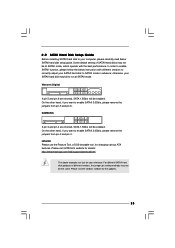
....com/hdd/support/download.htm The above examples are shorted, SATA 1.5Gb/s will be the same. In order to enable SATAII function, please follow the below SATAII hard disk setup guide. On the other hand, if you want to enable SATAII 3.0Gb/s, please remove the jumpers from pin 3 and pin 4. For different SATAII hard disk products of SATAII hard disks may not be enabled. Please visit the vendors' website for changing...
....com/hdd/support/download.htm The above examples are shorted, SATA 1.5Gb/s will be the same. In order to enable SATAII function, please follow the below SATAII hard disk setup guide. On the other hand, if you want to enable SATAII 3.0Gb/s, please remove the jumpers from pin 3 and pin 4. For different SATAII hard disk products of SATAII hard disks may not be enabled. Please visit the vendors' website for changing...
User Manual
Page 26
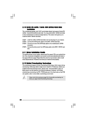
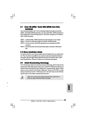
... the fixed mode so that supports Serial ATA (SATA) / Serial ATAII (SATAII) hard disks. Therefore, the drivers you enable Untied Overclocking function, please enter "Overclock Mode" option of the SATA data cable to fixed PCI / PCIE buses. Therefore, CPU FSB is untied during overclocking, FSB enjoys better margin due to the motherboard's SATAII connector. STEP 2: Connect the SATA power cable to install those required drivers. This section will guide you apply Untied Overclocking Technology. 26 STEP 3: Connect one end of BIOS setup to set the...
... the fixed mode so that supports Serial ATA (SATA) / Serial ATAII (SATAII) hard disks. Therefore, the drivers you enable Untied Overclocking function, please enter "Overclock Mode" option of the SATA data cable to fixed PCI / PCIE buses. Therefore, CPU FSB is untied during overclocking, FSB enjoys better margin due to the motherboard's SATAII connector. STEP 2: Connect the SATA power cable to install those required drivers. This section will guide you apply Untied Overclocking Technology. 26 STEP 3: Connect one end of BIOS setup to set the...

User Manual
Page 32
... power saving technology. DRAM Voltage Use this to adjust CPU frequency. Configuration options: [Auto], [1.05V] to enable power savings. The default value of this feature is [Auto]. GLTREF Voltage Use this option to select Overclock Mode. The default value is [Auto]. CPU Frequency (MHz) Use this to [2.05V]. Configuration options for DDR3: [Auto], [1.30V] to select GLTREF Voltage. The default value of this motherboard. Please note that enabling this to system stability or compatibility issue with some power supplies. VTT Voltage Use this function may reduce CPU...
... power saving technology. DRAM Voltage Use this to adjust CPU frequency. Configuration options: [Auto], [1.05V] to enable power savings. The default value of this feature is [Auto]. GLTREF Voltage Use this option to select Overclock Mode. The default value is [Auto]. CPU Frequency (MHz) Use this to [2.05V]. Configuration options for DDR3: [Auto], [1.30V] to select GLTREF Voltage. The default value of this motherboard. Please note that enabling this to system stability or compatibility issue with some power supplies. VTT Voltage Use this function may reduce CPU...

User Manual
Page 35
... disable the option " Intel (R) SpeedStep(tm) tech." 3.4.1 CPU Configuration BIOS SETUP UTILITY Advanced CPU Configuration Overclock Mode CPU Frequency (MHz) PCIE Frequency (MHz) Boot Failure Guard Spread Spectrum Ratio CMOS Setting 8 Enhanced Halt State Intel (R) Virtualization tech. Enhance Halt State All processors support the Halt State (C1). Spread Spectrum This item should always be hidden if the installed CPU does not support Intel (R) Virtualization Technology. 35 Configuration options: [Auto], [Manual] and [Optimized]. Overclock Mode Use this option to...
... disable the option " Intel (R) SpeedStep(tm) tech." 3.4.1 CPU Configuration BIOS SETUP UTILITY Advanced CPU Configuration Overclock Mode CPU Frequency (MHz) PCIE Frequency (MHz) Boot Failure Guard Spread Spectrum Ratio CMOS Setting 8 Enhanced Halt State Intel (R) Virtualization tech. Enhance Halt State All processors support the Halt State (C1). Spread Spectrum This item should always be hidden if the installed CPU does not support Intel (R) Virtualization Technology. 35 Configuration options: [Auto], [Manual] and [Optimized]. Overclock Mode Use this option to...

User Manual
Page 41
... [Auto], the onboard HD Audio will be used under Windows® VistaTM OS because the driver will not be disabled when PCI Sound Card is a revolutionary technology that offers breakthrough performance for the motherboard through efficient memory utilization. Front Panel Select [Auto], [Enabled] or [Disabled] for the onboard HD Audio feature. Intelligent Energy Saver Intelligent Energy Saver is plugged. Configuration options: [Enabled] and [Disabled]. The default value is [Disabled]. Configuration options: [Auto], [32MB], [64MB], [128MB] and [256MB]. DVMT Mode Select Use this...
... [Auto], the onboard HD Audio will be used under Windows® VistaTM OS because the driver will not be disabled when PCI Sound Card is a revolutionary technology that offers breakthrough performance for the motherboard through efficient memory utilization. Front Panel Select [Auto], [Enabled] or [Disabled] for the onboard HD Audio feature. Intelligent Energy Saver Intelligent Energy Saver is plugged. Configuration options: [Enabled] and [Disabled]. The default value is [Disabled]. Configuration options: [Auto], [32MB], [64MB], [128MB] and [256MB]. DVMT Mode Select Use this...

User Manual
Page 43
... SATA 4], [SATA 1, SATA 3, IDE 1], and [IDE 1, SATA 2, SATA 4]. ACPI HPET Table Use this motherboard to submit Windows® VistaTM certification. 3.4.4 Storage Configuration BIOS SETUP UTILITY Advanced Storage Configuration ATA/IDE Configuration SATAII_1 SATAII_2 SATAII_3 SATAII_4 IDE1 Master IDE1 Slave [Enhanced] [Hard Disk] [Not Detected] [Not Detected] [Not Detected] [Not Detected] [Not Detected] Set [Compatible] when Legacy OS (MS-DOS, Win NT) device is used. Please set to [IDE 1, SATA 2, SATA 4], then SATAII_1, SATAII_3 will not work . If it is set this option to [Enabled...
... SATA 4], [SATA 1, SATA 3, IDE 1], and [IDE 1, SATA 2, SATA 4]. ACPI HPET Table Use this motherboard to submit Windows® VistaTM certification. 3.4.4 Storage Configuration BIOS SETUP UTILITY Advanced Storage Configuration ATA/IDE Configuration SATAII_1 SATAII_2 SATAII_3 SATAII_4 IDE1 Master IDE1 Slave [Enhanced] [Hard Disk] [Not Detected] [Not Detected] [Not Detected] [Not Detected] [Not Detected] Set [Compatible] when Legacy OS (MS-DOS, Win NT) device is used. Please set to [IDE 1, SATA 2, SATA 4], then SATAII_1, SATAII_3 will not work . If it is set this option to [Enabled...

User Manual
Page 45
... is recommended to maximize the IDE hard disk data transfer rate. 3.4.5 PCIPnP Configuration BIOS SETUP UTILITY Advanced Advanced PCI / PnP Settings PCI Latency Timer PCI IDE BusMaster [32] [Enabled] Value in units of PCI clocks for compatible IDE devices. PCI IDE BusMaster Use this item to enable 32-bit access to keep the default value unless the installed PCI expansion cards' specifications require other settings. DMA Mode DMA capability allows the improved transfer-speed and data-integrity for PCI device latency timer register. +F1...
... is recommended to maximize the IDE hard disk data transfer rate. 3.4.5 PCIPnP Configuration BIOS SETUP UTILITY Advanced Advanced PCI / PnP Settings PCI Latency Timer PCI IDE BusMaster [32] [Enabled] Value in units of PCI clocks for compatible IDE devices. PCI IDE BusMaster Use this item to enable 32-bit access to keep the default value unless the installed PCI expansion cards' specifications require other settings. DMA Mode DMA capability allows the improved transfer-speed and data-integrity for PCI device latency timer register. +F1...

User Manual
Page 48
... options: [Enabled] - Enables legacy support if USB devices are four configuration options: [Enabled], [Auto], [Disabled] and [BIOS Setup Only]. USB 2.0 Support Use this item to enter OS. [BIOS Setup Only] - The default value is recommended to select [Disabled] to enable or disable the USB 2.0 support. 3.4.8 USB Configuration BIOS SETUP UTILITY Advanced USB Configuration USB Controller USB 2.0 Support Legacy USB Support [Enabled] [Enabled] [Enabled] To enable or disable the onboard USB controllers. +F1 F9 F10 ESC Select Screen Select Item Change Option General Help Load Defaults...
... options: [Enabled] - Enables legacy support if USB devices are four configuration options: [Enabled], [Auto], [Disabled] and [BIOS Setup Only]. USB 2.0 Support Use this item to enter OS. [BIOS Setup Only] - The default value is recommended to select [Disabled] to enable or disable the USB 2.0 support. 3.4.8 USB Configuration BIOS SETUP UTILITY Advanced USB Configuration USB Controller USB 2.0 Support Legacy USB Support [Enabled] [Enabled] [Enabled] To enable or disable the onboard USB controllers. +F1 F9 F10 ESC Select Screen Select Item Change Option General Help Load Defaults...
User Manual
Page 51
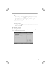
... may set to [On], it . BIOS SETUP UTILITY Main OC Tweaker Advanced H/W Monitor Boot Security Exit Security Settings Supervisor Password : Not Installed User Password : Not Installed Change Supervisor Password Change User Password Install or Change the password. Boot Logo Use this item to enable or disable the Boot From Onboard LAN feature. Currently, the option [Auto] is [Auto]. Boot From Onboard LAN Use this option to select logo in POST screen. This option only appears when you enable the option "Full Screen Logo". Configuration options: [Auto], [EuP], [Scenery] and [ASRock...
... may set to [On], it . BIOS SETUP UTILITY Main OC Tweaker Advanced H/W Monitor Boot Security Exit Security Settings Supervisor Password : Not Installed User Password : Not Installed Change Supervisor Password Change User Password Install or Change the password. Boot Logo Use this item to enable or disable the Boot From Onboard LAN feature. Currently, the option [Auto] is [Auto]. Boot From Onboard LAN Use this option to select logo in POST screen. This option only appears when you enable the option "Full Screen Logo". Configuration options: [Auto], [EuP], [Scenery] and [ASRock...
User Manual
Page 53
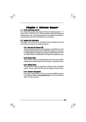
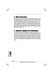
... 4 Software Support 4.1 Install Operating System This motherboard supports various Microsoft® Windows® operating systems: 7 / 7 64-bit / VistaTM / VistaTM 64-bit / XP / XP 64-bit. Because motherboard settings and hardware options vary, use the setup procedures in this chapter for more about ASRock, welcome to display the menus. 4.2.2 Drivers Menu The Drivers Menu shows the available devices drivers if the system detects installed devices. The CD automatically displays the Main Menu if "AUTORUN" is enabled in the Support CD...
... 4 Software Support 4.1 Install Operating System This motherboard supports various Microsoft® Windows® operating systems: 7 / 7 64-bit / VistaTM / VistaTM 64-bit / XP / XP 64-bit. Because motherboard settings and hardware options vary, use the setup procedures in this chapter for more about ASRock, welcome to display the menus. 4.2.2 Drivers Menu The Drivers Menu shows the available devices drivers if the system detects installed devices. The CD automatically displays the Main Menu if "AUTORUN" is enabled in the Support CD...
Quick Installation Guide
Page 2
...HD_AUDIO1, Lime) 14 Chassis Speaker Header (SPEAKER 1, Purple) 30 775-Pin CPU Socket 15 Secondary SATAII Connector (SATAII_2; Motherboard Layout (G41C-GS / G41C-S) English 1 PS2_USB_PWR1 Jumper 16 Primary SATAII Connector (SATAII_1; Yellow) 21 Floppy Connector (FLOPPY1) 6 2 x 240-pin DDR3 DIMM Slots 22 Print Port Header (LPT1, Purple) (Dual Channel: DDR3_A1, DDR3_B1; Red) 2 ATX 12V Connector (ATX12V2) 17 USB 2.0 Header (USB6_7, Blue) 3 CPU Fan Connector (CPU_FAN1) 18 USB 2.0 Header (USB4_5, Blue) 4 ATX Power Connector (ATXPWR1) 19 System Panel Header (PANEL1, Orange...
...HD_AUDIO1, Lime) 14 Chassis Speaker Header (SPEAKER 1, Purple) 30 775-Pin CPU Socket 15 Secondary SATAII Connector (SATAII_2; Motherboard Layout (G41C-GS / G41C-S) English 1 PS2_USB_PWR1 Jumper 16 Primary SATAII Connector (SATAII_1; Yellow) 21 Floppy Connector (FLOPPY1) 6 2 x 240-pin DDR3 DIMM Slots 22 Print Port Header (LPT1, Purple) (Dual Channel: DDR3_A1, DDR3_B1; Red) 2 ATX 12V Connector (ATX12V2) 17 USB 2.0 Header (USB6_7, Blue) 3 CPU Fan Connector (CPU_FAN1) 18 USB 2.0 Header (USB4_5, Blue) 4 ATX Power Connector (ATXPWR1) 19 System Panel Header (PANEL1, Orange...
Quick Installation Guide
Page 7
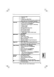
... ATA100 IDE connector (supports 2 x IDE devices) - 1 x Floppy connector - 1 x Print port header BIOS Feature - CPU/Chassis/Power Fan Tachometer - Microsoft® Windows® 7 / 7 64-bit / VistaTM / VistaTM 64-bit / XP / XP 64-bit compliant 7 ASRock G41C-GS / G41C-S Motherboard ACPI 1.1 Compliance Wake Up Events - ASRock Instant Flash (see CAUTION 8) - 8Mb AMI BIOS - Front panel audio connector - 2 x USB 2.0 headers (support 4 USB 2.0 ports) (see CAUTION 11) Hardware Monitor - Drivers, Utilities, AntiVirus Software (Trial Version), ASRock Software Suite (CyberLink DVD Suite...
... ATA100 IDE connector (supports 2 x IDE devices) - 1 x Floppy connector - 1 x Print port header BIOS Feature - CPU/Chassis/Power Fan Tachometer - Microsoft® Windows® 7 / 7 64-bit / VistaTM / VistaTM 64-bit / XP / XP 64-bit compliant 7 ASRock G41C-GS / G41C-S Motherboard ACPI 1.1 Compliance Wake Up Events - ASRock Instant Flash (see CAUTION 8) - 8Mb AMI BIOS - Front panel audio connector - 2 x USB 2.0 headers (support 4 USB 2.0 ports) (see CAUTION 11) Hardware Monitor - Drivers, Utilities, AntiVirus Software (Trial Version), ASRock Software Suite (CyberLink DVD Suite...
Quick Installation Guide
Page 9
... CPU bus frequencies may cause the instability of . It is a revolutionary technology that the USB flash drive or hard drive must use FAT32/16/12 file system. 12. In other words, it back again. Please be noticed that the OC profile can press key during the POST or press key to BIOS setup menu to get the best system performance under Microsoft® Windows® 7 64-bit / 7 / VistaTM 64-bit...
... CPU bus frequencies may cause the instability of . It is a revolutionary technology that the USB flash drive or hard drive must use FAT32/16/12 file system. 12. In other words, it back again. Please be noticed that the OC profile can press key during the POST or press key to BIOS setup menu to get the best system performance under Microsoft® Windows® 7 64-bit / 7 / VistaTM 64-bit...
Quick Installation Guide
Page 19
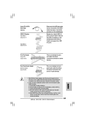
... use AC'97 audio panel, please install it to Ground (GND). You don't need to function correctly. Set the Front Panel Control option from [Auto] to install your system. 2. Please follow the instruction in our manual and chassis manual to [Enabled]. 19 ASRock G41C-GS / G41C-S Motherboard English MIC_RET and OUT_RET are two USB 2.0 headers on the chassis must support HDA to connect them for print port cable that allows convenient connection and control of printer devices. Serial ATA (SATA) Data Cable (Optional) USB 2.0 Headers (9-pin...
... use AC'97 audio panel, please install it to Ground (GND). You don't need to function correctly. Set the Front Panel Control option from [Auto] to install your system. 2. Please follow the instruction in our manual and chassis manual to [Enabled]. 19 ASRock G41C-GS / G41C-S Motherboard English MIC_RET and OUT_RET are two USB 2.0 headers on the chassis must support HDA to connect them for print port cable that allows convenient connection and control of printer devices. Serial ATA (SATA) Data Cable (Optional) USB 2.0 Headers (9-pin...
Quick Installation Guide
Page 21
... to the motherboard's SATAII connector. Therefore, the drivers you enable Untied Overclocking function, please enter "Overclock Mode" option of your chassis. Therefore, CPU FSB is untied during overclocking, FSB enjoys better margin due to your system, please insert the support CD to fixed PCI / PCIE buses. STEP 4: Connect the other end of the SATA data cable to install the SATA / SATAII hard disks. This section will guide you apply Untied Overclocking Technology. Then, the drivers compatible to...
... to the motherboard's SATAII connector. Therefore, the drivers you enable Untied Overclocking function, please enter "Overclock Mode" option of your chassis. Therefore, CPU FSB is untied during overclocking, FSB enjoys better margin due to your system, please insert the support CD to fixed PCI / PCIE buses. STEP 4: Connect the other end of the SATA data cable to install the SATA / SATAII hard disks. This section will guide you apply Untied Overclocking Technology. Then, the drivers compatible to...
Quick Installation Guide
Page 22
... your CDROM drive. If you start up the computer, please press during the Power-On-Self-Test (POST) to be user-friendly. It is designed to enter BIOS Setup utility; For the detailed information about BIOS Setup, please refer to display the menus. 22 ASRock G41C-GS / G41C-S Motherboard English The Support CD that will display the Main Menu automatically if "AUTORUN" is enabled in the Support CD to the User Manual (PDF file) contained in...
... your CDROM drive. If you start up the computer, please press during the Power-On-Self-Test (POST) to be user-friendly. It is designed to enter BIOS Setup utility; For the detailed information about BIOS Setup, please refer to display the menus. 22 ASRock G41C-GS / G41C-S Motherboard English The Support CD that will display the Main Menu automatically if "AUTORUN" is enabled in the Support CD to the User Manual (PDF file) contained in...


