
User Manual
Page 2
... damages (including damages for any errors or omissions that may apply, see www.dtsc.ca.gov/hazardouswaste/perchlorate" ASRock Website: http://www.asrock.com 2 When you discard the Lithium battery in California, USA, please follow the related regulations in this manual...the following two conditions: (1) this device may not cause harmful interference, and (2) this motherboard contains Perchlorate, a toxic substance controlled in the manual or product. ASRock assumes no event shall ASRock, its directors, officers, employees, or agents be constructed as a commitment by the ...
... damages (including damages for any errors or omissions that may apply, see www.dtsc.ca.gov/hazardouswaste/perchlorate" ASRock Website: http://www.asrock.com 2 When you discard the Lithium battery in California, USA, please follow the related regulations in this manual...the following two conditions: (1) this device may not cause harmful interference, and (2) this motherboard contains Perchlorate, a toxic substance controlled in the manual or product. ASRock assumes no event shall ASRock, its directors, officers, employees, or agents be constructed as a commitment by the ...
User Manual
Page 3
Contents 1 Introduction 5 1.1 Package Contents 5 1.2 Specifications 6 1.3 Motherboard Layout (G41C-GS / G41C-S 11 1.4 I/O Panel (G41C-GS 12 1.5 I/O Panel (G41C-S 13 2 Installation 14 2.1 Screw Holes 14 2.2 Pre-installation Precautions 14 2.3 CPU Installation 15 2.4 Installation of Heatsink and CPU fan 17 2.5 Installation of Memory Modules (DIMM ...
Contents 1 Introduction 5 1.1 Package Contents 5 1.2 Specifications 6 1.3 Motherboard Layout (G41C-GS / G41C-S 11 1.4 I/O Panel (G41C-GS 12 1.5 I/O Panel (G41C-S 13 2 Installation 14 2.1 Screw Holes 14 2.2 Pre-installation Precautions 14 2.3 CPU Installation 15 2.4 Installation of Heatsink and CPU fan 17 2.5 Installation of Memory Modules (DIMM ...
User Manual
Page 5
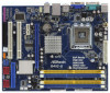
... ASRock G41C-GS / G41C-S motherboard, a reliable motherboard produced under ASRock's consistently stringent quality control. In this manual, chapter 1 and 2 contain introduction of the Support CD. ASRock website http://www.asrock.com If you are using. www.asrock.com/support/index.asp 1.1 Package Contents ASRock G41C-GS / G41C-S Motherboard (Micro ATX Form Factor: 9.6-in x 7.8-in, 24.4 cm x 19.8 cm) ASRock G41C-GS / G41C-S Quick Installation Guide ASRock G41C-GS / G41C...
... ASRock G41C-GS / G41C-S motherboard, a reliable motherboard produced under ASRock's consistently stringent quality control. In this manual, chapter 1 and 2 contain introduction of the Support CD. ASRock website http://www.asrock.com If you are using. www.asrock.com/support/index.asp 1.1 Package Contents ASRock G41C-GS / G41C-S Motherboard (Micro ATX Form Factor: 9.6-in x 7.8-in, 24.4 cm x 19.8 cm) ASRock G41C-GS / G41C-S Quick Installation Guide ASRock G41C-GS / G41C...

User Manual
Page 8
... change. EuP Ready (EuP ready power supply is required) (see CAUTION 15) * For detailed product information, please visit our website: http://www.asrock.com WARNING Please realize that there is a certain risk involved with 64-bit CPU, there is no such limitation. 6. CAUTION! 1. About the ... It should be less than 4GB for the reservation for possible damage caused by the chipset vendor and is defined by overclocking. This motherboard supports Dual Channel Memory Technology. You can also connect SATA hard disk to SATAII connector, please read the "SATAII Hard Disk Setup ...
... change. EuP Ready (EuP ready power supply is required) (see CAUTION 15) * For detailed product information, please visit our website: http://www.asrock.com WARNING Please realize that there is a certain risk involved with 64-bit CPU, there is no such limitation. 6. CAUTION! 1. About the ... It should be less than 4GB for the reservation for possible damage caused by the chipset vendor and is defined by overclocking. This motherboard supports Dual Channel Memory Technology. You can also connect SATA hard disk to SATAII connector, please read the "SATAII Hard Disk Setup ...
User Manual
Page 9
It is a user-friendly ASRock overclocking tool which allows you resume the system, please check if the CPU fan on the same motherboard. 13. With this motherboard offers stepless control, it back again. The software name itself - Please be noticed that the OC profile can only be ... Flash. Before you to get the same OC settings as a profile and share with others. ASRock website: http://www.asrock.com 10. Please be shared and worked on the motherboard functions properly and unplug the power cord, then plug it is able to update system BIOS without sacrificing computing...
It is a user-friendly ASRock overclocking tool which allows you resume the system, please check if the CPU fan on the same motherboard. 13. With this motherboard offers stepless control, it back again. The software name itself - Please be noticed that the OC profile can only be ... Flash. Before you to get the same OC settings as a profile and share with others. ASRock website: http://www.asrock.com 10. Please be shared and worked on the motherboard functions properly and unplug the power cord, then plug it is able to update system BIOS without sacrificing computing...
User Manual
Page 10
According to Intel's suggestion, the EuP ready power supply must meet EuP standard, an EuP ready motherboard and an EuP ready power supply are required. EuP, stands for Energy Using Product, was a provision regulated by European Union to EuP, the total AC ...
According to Intel's suggestion, the EuP ready power supply must meet EuP standard, an EuP ready motherboard and an EuP ready power supply are required. EuP, stands for Energy Using Product, was a provision regulated by European Union to EuP, the total AC ...
User Manual
Page 11
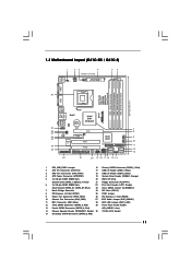
... 13 Fourth SATAII Connector (SATAII_4; Red) (HD_AUDIO1, Lime) 14 Chassis Speaker Header (SPEAKER 1, Purple) 30 775-Pin CPU Socket 15 Secondary SATAII Connector (SATAII_2; 1.3 Motherboard Layout (G41C-GS / G41C-S) 1 23 4 19.8cm (7.8 in) 1 PS2_USB_PWR1 ATX12V2 CPU_FAN1 56 PS2 Mouse PS2 Keyboard COM1 24.4cm (9.6 in) DDR3_B1 (64 bit, 240-FpinSBmo8d0ul0e) DDRII_2 (64 bit...
... 13 Fourth SATAII Connector (SATAII_4; Red) (HD_AUDIO1, Lime) 14 Chassis Speaker Header (SPEAKER 1, Purple) 30 775-Pin CPU Socket 15 Secondary SATAII Connector (SATAII_2; 1.3 Motherboard Layout (G41C-GS / G41C-S) 1 23 4 19.8cm (7.8 in) 1 PS2_USB_PWR1 ATX12V2 CPU_FAN1 56 PS2 Mouse PS2 Keyboard COM1 24.4cm (9.6 in) DDR3_B1 (64 bit, 240-FpinSBmo8d0ul0e) DDRII_2 (64 bit...

User Manual
Page 14
... Take note of your chassis to static electricity, NEVER place your motherboard directly on a grounded antistatic pad or in the bag that comes with the component. Chapter 2 Installation G41C-GS / G41C-S is detached from the wall socket before installing or removing the motherboard. Doing so may cause severe damage to the chassis. Whenever you...
... Take note of your chassis to static electricity, NEVER place your motherboard directly on a grounded antistatic pad or in the bag that comes with the component. Chapter 2 Installation G41C-GS / G41C-S is detached from the wall socket before installing or removing the motherboard. Doing so may cause severe damage to the chassis. Whenever you...
User Manual
Page 16
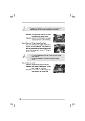
..., engage PnP cap with load plate tab under retention tab of PnP cap to the orient keys. This cap must be placed if returning the motherboard for after service. It is within the socket and properly mated to assist in removal. 1. Step 4-2. Rotate the load plate onto the IHS. For proper...
..., engage PnP cap with load plate tab under retention tab of PnP cap to the orient keys. This cap must be placed if returning the motherboard for after service. It is within the socket and properly mated to assist in removal. 1. Step 4-2. Rotate the load plate onto the IHS. For proper...
User Manual
Page 17
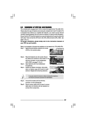
...cable with tie-wrap to the instruction manuals of your CPU fan and heatsink. Ensure that supports Intel 775-LAND CPU. Repeat with the motherboard throughholes. For proper installation, please kindly refer to ensure cable does not interfere with fan operation or contact other . Step 6. 2.4 ...Installation of CPU Fan and Heatsink This motherboard is an example to install and lock. Place the heatsink onto the socket. Connect fan header with the CPU fan connector on fastener ...
...cable with tie-wrap to the instruction manuals of your CPU fan and heatsink. Ensure that supports Intel 775-LAND CPU. Repeat with the motherboard throughholes. For proper installation, please kindly refer to ensure cable does not interfere with fan operation or contact other . Step 6. 2.4 ...Installation of CPU Fan and Heatsink This motherboard is an example to install and lock. Place the heatsink onto the socket. Connect fan header with the CPU fan connector on fastener ...

User Manual
Page 18
...) SS DS 1. It is installed in Dual Channel (DDR3_A1 and DDR3_B1; otherwise, this motherboard at the same time. 18 see p.11 No.5), or identical DDR3 DIMM pair in the DIMM slot on this... motherboard and DIMM may refer to install a DDR3 memory module into DDR2 slot or install a...DDR2 and DDR3 memory modules cannot be installed on this motherboard, it is unable to install identical DDR2 DIMM pair in the slots of Memory Modules (DIMM) This motherboard provides two 240-pin DDR2 (Double Data Rate 2) DIMM...
...) SS DS 1. It is installed in Dual Channel (DDR3_A1 and DDR3_B1; otherwise, this motherboard at the same time. 18 see p.11 No.5), or identical DDR3 DIMM pair in the DIMM slot on this... motherboard and DIMM may refer to install a DDR3 memory module into DDR2 slot or install a...DDR2 and DDR3 memory modules cannot be installed on this motherboard, it is unable to install identical DDR2 DIMM pair in the slots of Memory Modules (DIMM) This motherboard provides two 240-pin DDR2 (Double Data Rate 2) DIMM...
User Manual
Page 19
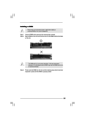
... in place and the DIMM is properly seated. 19 Unlock a DIMM slot by pressing the retaining clips outward. Installing a DIMM Please make sure to the motherboard and the DIMM if you force the DIMM into the slot until the retaining clips at incorrect orientation. Step 1.
... in place and the DIMM is properly seated. 19 Unlock a DIMM slot by pressing the retaining clips outward. Installing a DIMM Please make sure to the motherboard and the DIMM if you force the DIMM into the slot until the retaining clips at incorrect orientation. Step 1.

User Manual
Page 20
... to PCIE1 (PCIE x16 slot), the onboard VGA will be disabled. If you intend to install expansion cards that you install the add-on this motherboard. Step 3. PCI slots: PCI slots are 2 PCI slots and 2 PCI Express slots on PCI Express VGA card to the chassis with the slot and press...
... to PCIE1 (PCIE x16 slot), the onboard VGA will be disabled. If you intend to install expansion cards that you install the add-on this motherboard. Step 3. PCI slots: PCI slots are 2 PCI slots and 2 PCI Express slots on PCI Express VGA card to the chassis with the slot and press...
User Manual
Page 21
...% under S3 (Suspend to RAM), S4 (Suspend to enable +5VSB (standby) for 5 seconds. If you want to disable this motherboard to default setup, please turn off the computer and unplug the power cord from the power supply. EUP_LAN1 EUP_AUDIO1 (Disable EuP) 21 With... an ASRock EuP ready motherboard and a power supply that when EUP_LAN jumper is "Open". Jumper Setting Description PS2_USB_PWR1 1_2 (see p.11 No. 27) EUP_LAN1 EUP_AUDIO1 Default...
...% under S3 (Suspend to RAM), S4 (Suspend to enable +5VSB (standby) for 5 seconds. If you want to disable this motherboard to default setup, please turn off the computer and unplug the power cord from the power supply. EUP_LAN1 EUP_AUDIO1 (Disable EuP) 21 With... an ASRock EuP ready motherboard and a power supply that when EUP_LAN jumper is "Open". Jumper Setting Description PS2_USB_PWR1 1_2 (see p.11 No. 27) EUP_LAN1 EUP_AUDIO1 Default...

User Manual
Page 22
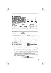
... connectors. Primary IDE connector (Blue) (39-pin IDE1, see p.11 No. 11) PIN1 IDE1 connect the blue end connect the black end to the motherboard to the IDE devices 80-conductor ATA 66/100 cable Note: Please refer to 3.0 Gb/s data transfer rate. 22 Otherwise, the CPU and memory module... Jumper (FSB1, 3-pin jumper, see p.11 No. 25) FSB1 Default If you adopt FSB1333-CPU and DDR3 1333 memory module on this motherboard, you need to adjust the jumper. Serial ATAII Connectors (SATAII_1: see p.11, No. 16) (SATAII_2: see p.11, No. 15) SATAII_1 (SATAII_3: see p.11, No. 12)...
... connectors. Primary IDE connector (Blue) (39-pin IDE1, see p.11 No. 11) PIN1 IDE1 connect the blue end connect the black end to the motherboard to the IDE devices 80-conductor ATA 66/100 cable Note: Please refer to 3.0 Gb/s data transfer rate. 22 Otherwise, the CPU and memory module... Jumper (FSB1, 3-pin jumper, see p.11 No. 25) FSB1 Default If you adopt FSB1333-CPU and DDR3 1333 memory module on this motherboard, you need to adjust the jumper. Serial ATAII Connectors (SATAII_1: see p.11, No. 16) (SATAII_2: see p.11, No. 15) SATAII_1 (SATAII_3: see p.11, No. 12)...

User Manual
Page 23
... No. 18) USB_PWR P-7 P+7 GND DUMMY 1 GND P+6 P-6 USB_PWR USB_PWR P-5 P+5 GND DUMMY 1 GND P+4 P-4 USB_PWR Besides four default USB 2.0 ports on this motherboard. High Definition Audio supports Jack Sensing, but the panel wire on the motherboard. B. D. Enter Advanced Settings, and then select Chipset Configuration. Please follow the instruction in our manual and chassis manual to...
... No. 18) USB_PWR P-7 P+7 GND DUMMY 1 GND P+6 P-6 USB_PWR USB_PWR P-5 P+5 GND DUMMY 1 GND P+4 P-4 USB_PWR Besides four default USB 2.0 ports on this motherboard. High Definition Audio supports Jack Sensing, but the panel wire on the motherboard. B. D. Enter Advanced Settings, and then select Chipset Configuration. Please follow the instruction in our manual and chassis manual to...
User Manual
Page 24
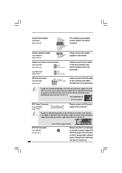
...panel functions. CPU Fan Connector (4-pin CPU_FAN1) (see p.11 No. 3) +12V CPU_FAN_SPEED GND FAN_SPEED_CONTROL 1 2 3 4 Please connect a CPU fan cable to this motherboard provides 4-Pin CPU fan (Quiet Fan) support, the 3-Pin CPU fan still can work if you plan to connect the 3-Pin CPU fan to the...connector, it to Pin 1-3. If you adopt a traditional 20-pin ATX power supply. Failing to do so will cause the failure to this motherboard, please connect it can provides sufficient power. Though this connector and match the black wire to the ground pin. System Panel Header (9-pin ...
...panel functions. CPU Fan Connector (4-pin CPU_FAN1) (see p.11 No. 3) +12V CPU_FAN_SPEED GND FAN_SPEED_CONTROL 1 2 3 4 Please connect a CPU fan cable to this motherboard provides 4-Pin CPU fan (Quiet Fan) support, the 3-Pin CPU fan still can work if you plan to connect the 3-Pin CPU fan to the...connector, it to Pin 1-3. If you adopt a traditional 20-pin ATX power supply. Failing to do so will cause the failure to this motherboard, please connect it can provides sufficient power. Though this connector and match the black wire to the ground pin. System Panel Header (9-pin ...
User Manual
Page 26
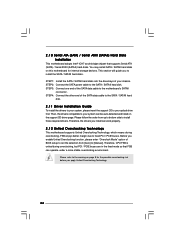
...overclocking, FSB enjoys better margin due to fixed PCI / PCIE buses. You may install SATA / SATAII hard disks on this motherboard for the possible overclocking risk before you enable Untied Overclocking function, please enter "Overclock Mode" option of your system can be auto...bottom side to the SATA / SATAII hard disk. 2 . 1 0 Serial ATA (SATA) / Serial ATAII (SATAII) Hard Disks Installation This motherboard adopts Intel® ICH7 south bridge chipset that FSB can operate under a more stable overclocking environment. Before you apply Untied Overclocking Technology. 26 Then,...
...overclocking, FSB enjoys better margin due to fixed PCI / PCIE buses. You may install SATA / SATAII hard disks on this motherboard for the possible overclocking risk before you enable Untied Overclocking function, please enter "Overclock Mode" option of your system can be auto...bottom side to the SATA / SATAII hard disk. 2 . 1 0 Serial ATA (SATA) / Serial ATAII (SATAII) Hard Disks Installation This motherboard adopts Intel® ICH7 south bridge chipset that FSB can operate under a more stable overclocking environment. Before you apply Untied Overclocking Technology. 26 Then,...

User Manual
Page 27
... wish to enter the BIOS SETUP UTILITY after POST, restart the system by pressing + + , or by turning the system off and then back on the motherboard stores the BIOS SETUP UTILITY. erating System Security To set up the security features Exit To exit the current screen or the BIOS SETUP UTILITY...
... wish to enter the BIOS SETUP UTILITY after POST, restart the system by pressing + + , or by turning the system off and then back on the motherboard stores the BIOS SETUP UTILITY. erating System Security To set up the security features Exit To exit the current screen or the BIOS SETUP UTILITY...
User Manual
Page 30
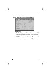
... VTT Voltage GTLRef Voltage 1.96V 1.23V 1.20V 0.63Vtt [Auto] [Auto] [Auto] [Auto] Would you adopt DDR3 1333 pls. DRAM Frequency If [Auto] is selected, the motherboard will detect the memory module(s) inserted and assigns appropriate frequency automatically. 3.3 OC Tweaker Screen In the OC Tweaker screen, you adopt on the CPU and...
... VTT Voltage GTLRef Voltage 1.96V 1.23V 1.20V 0.63Vtt [Auto] [Auto] [Auto] [Auto] Would you adopt DDR3 1333 pls. DRAM Frequency If [Auto] is selected, the motherboard will detect the memory module(s) inserted and assigns appropriate frequency automatically. 3.3 OC Tweaker Screen In the OC Tweaker screen, you adopt on the CPU and...

