User Manual
Page 5
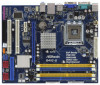
... quality and endurance. You may find the latest VGA cards and CPU support lists on ASRock website without notice. www.asrock.com/support/index.asp 1.1 Package Contents ASRock G41C-GS / G41C-S Motherboard (Micro ATX Form Factor: 9.6-in x 7.8-in, 24.4 cm x 19.8 cm) ASRock G41C-GS / G41C-S Quick Installation Guide ASRock G41C-GS / G41C-S Support CD Two Serial ATA (SATA) Data Cables (Optional) One I/O Panel Shield...
... quality and endurance. You may find the latest VGA cards and CPU support lists on ASRock website without notice. www.asrock.com/support/index.asp 1.1 Package Contents ASRock G41C-GS / G41C-S Motherboard (Micro ATX Form Factor: 9.6-in x 7.8-in, 24.4 cm x 19.8 cm) ASRock G41C-GS / G41C-S Quick Installation Guide ASRock G41C-GS / G41C-S Support CD Two Serial ATA (SATA) Data Cables (Optional) One I/O Panel Shield...

User Manual
Page 6
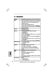
...x1 slot - 2 x PCI slots - Max. Intel® Graphics Media Accelerator X4500 - Max. G41C-GS: Realtek PCIE x1 Gigabit LAN RTL8111DL, speed 10/100/1000 Mb/s - G41C-S: Realtek PCIE x1 LAN 8103EL / 8102EL, speed 10/100 Mb/s - Micro ATX Form Factor: ... VT1705 Audio Codec) - Supports Hyper-Threading Technology (see CAUTION 2) - shared memory 1759MB (see CAUTION 5) - 2 x DDR2 DIMM slots - Supports EM64T CPU - Pixel Shader 4.0, DirectX 10 - Supports FSB1333/1066/800/533 MHz - Supports D-Sub with max. 1.2 Specifications Platform CPU Chipset Memory Expansion Slot Graphics ...
...x1 slot - 2 x PCI slots - Max. Intel® Graphics Media Accelerator X4500 - Max. G41C-GS: Realtek PCIE x1 Gigabit LAN RTL8111DL, speed 10/100/1000 Mb/s - G41C-S: Realtek PCIE x1 LAN 8103EL / 8102EL, speed 10/100 Mb/s - Micro ATX Form Factor: ... VT1705 Audio Codec) - Supports Hyper-Threading Technology (see CAUTION 2) - shared memory 1759MB (see CAUTION 5) - 2 x DDR2 DIMM slots - Supports EM64T CPU - Pixel Shader 4.0, DirectX 10 - Supports FSB1333/1066/800/533 MHz - Supports D-Sub with max. 1.2 Specifications Platform CPU Chipset Memory Expansion Slot Graphics ...

User Manual
Page 7
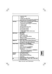
... Suite (CyberLink DVD Suite and Creative Sound Blaster X-Fi MB) (OEM and Trial Version) - ASRock Instant Flash (see CAUTION 7) - 1 x ATA100 IDE connector (supports 2 x IDE devices) - 1 x Floppy connector - 1 x Print port header - Hybrid Booster: - CPU Temperature Sensing - CPU/Chassis/Power Fan Tachometer - Microsoft® Windows® 7 / 7 64-bit / VistaTM / VistaTM 64-bit / XP / XP 64-bit...
... Suite (CyberLink DVD Suite and Creative Sound Blaster X-Fi MB) (OEM and Trial Version) - ASRock Instant Flash (see CAUTION 7) - 1 x ATA100 IDE connector (supports 2 x IDE devices) - 1 x Floppy connector - 1 x Print port header - Hybrid Booster: - CPU Temperature Sensing - CPU/Chassis/Power Fan Tachometer - Microsoft® Windows® 7 / 7 64-bit / VistaTM / VistaTM 64-bit / XP / XP 64-bit...

User Manual
Page 8
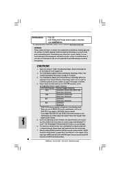
... can also connect SATA hard disk to adjust the jumper. FCC, CE - We are not responsible for proper installation. 4. This motherboard supports Dual Channel Memory Technology. About the setting of memory modules on page 25 to SATAII mode. Before you need to SATAII connector directly. ...required) (see CAUTION 15) * For detailed product information, please visit our website: http://www.asrock.com WARNING Please realize that there is a certain risk involved with 64-bit CPU, there is subject to the operating system limitation, the actual memory size may affect your system ...
... can also connect SATA hard disk to adjust the jumper. FCC, CE - We are not responsible for proper installation. 4. This motherboard supports Dual Channel Memory Technology. About the setting of memory modules on page 25 to SATAII mode. Before you need to SATAII connector directly. ...required) (see CAUTION 15) * For detailed product information, please visit our website: http://www.asrock.com WARNING Please realize that there is a certain risk involved with 64-bit CPU, there is subject to the operating system limitation, the actual memory size may affect your system ...
User Manual
Page 16
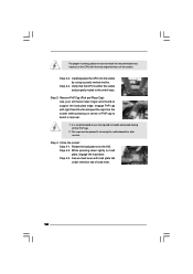
... motion. While pressing down lightly on center of PnP cap to the orient keys. Verify that the CPU is recommended to use the cap tab to match the two orientation key notches of the CPU with load plate tab under retention tab of the socket. Remove PnP Cap (Pick and Place Cap...): Use your left hand index finger and thumb to support the load plate edge, engage PnP cap with right hand thumb and...
... motion. While pressing down lightly on center of PnP cap to the orient keys. Verify that the CPU is recommended to use the cap tab to match the two orientation key notches of the CPU with load plate tab under retention tab of the socket. Remove PnP Cap (Pick and Place Cap...): Use your left hand index finger and thumb to support the load plate edge, engage PnP cap with right hand thumb and...
User Manual
Page 17
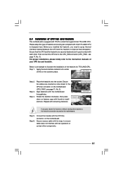
... the installation of the heatsink for 775-LAND CPU. Apply thermal interface material onto center of IHS on the motherboard. Ensure that supports Intel 775-LAND CPU. If you need to spray thermal interface material between the CPU and the heatsink to improve heat dissipation. Connect... fan header with each other components. 17 2.4 Installation of CPU Fan and Heatsink This motherboard is...
... the installation of the heatsink for 775-LAND CPU. Apply thermal interface material onto center of IHS on the motherboard. Ensure that supports Intel 775-LAND CPU. If you need to spray thermal interface material between the CPU and the heatsink to improve heat dissipation. Connect... fan header with each other components. 17 2.4 Installation of CPU Fan and Heatsink This motherboard is...

User Manual
Page 22
...black end to the motherboard to the IDE devices 80-conductor ATA 66/100 cable Note: Please refer to adjust the jumper. Otherwise, the CPU and memory module may not work properly on this motherboard. FSB1 Jumper (FSB1, 3-pin jumper, see p.11, No. 13) SATAII_2 ...SATAII_3 SATAII_4 These four Serial ATAII (SATAII) connectors support SATAII or SATA hard disk for internal storage devices. Please short pin2, pin3 for the details. Serial ATAII Connectors (SATAII_1: see p.11, No. 16...
...black end to the motherboard to the IDE devices 80-conductor ATA 66/100 cable Note: Please refer to adjust the jumper. Otherwise, the CPU and memory module may not work properly on this motherboard. FSB1 Jumper (FSB1, 3-pin jumper, see p.11, No. 13) SATAII_2 ...SATAII_3 SATAII_4 These four Serial ATAII (SATAII) connectors support SATAII or SATA hard disk for internal storage devices. Please short pin2, pin3 for the details. Serial ATAII Connectors (SATAII_1: see p.11, No. 16...
User Manual
Page 24
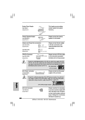
...supply to this header. Pin 1-3 Connected 3-Pin Fan Installation ATX Power Connector 24 (24-pin ATXPWR1) (see p.11 No. 3) +12V CPU_FAN_SPEED GND FAN_SPEED_CONTROL 1 2 3 4 Please connect a CPU fan cable to this connector and match the black wire to the ground pin. Please connect the chassis speaker to this connector. 1 Though this motherboard... supply, please plug your power supply along with ATX 12V plug to this connector so that it to power up. Though this motherboard provides 4-Pin CPU fan (Quiet Fan) support, the 3-Pin CPU fan still can provides sufficient power.
...supply to this header. Pin 1-3 Connected 3-Pin Fan Installation ATX Power Connector 24 (24-pin ATXPWR1) (see p.11 No. 3) +12V CPU_FAN_SPEED GND FAN_SPEED_CONTROL 1 2 3 4 Please connect a CPU fan cable to this connector and match the black wire to the ground pin. Please connect the chassis speaker to this connector. 1 Though this motherboard... supply, please plug your power supply along with ATX 12V plug to this connector so that it to power up. Though this motherboard provides 4-Pin CPU fan (Quiet Fan) support, the 3-Pin CPU fan still can provides sufficient power.
User Manual
Page 26
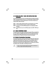
...before you install can work properly. 2 . 1 2 Untied Overclocking Technology This motherboard supports Untied Overclocking Technology, which means during overclocking, but PCI / PCIE buses are in the fixed mode so that supports Serial ATA (SATA) / Serial ATAII (SATAII) hard disks. STEP 1: Install the...SATAII hard disk. Then, the drivers compatible to fixed PCI / PCIE buses. Therefore, the drivers you apply Untied Overclocking Technology. 26 Therefore, CPU FSB is untied during overclocking, FSB enjoys better margin due to your chassis. 2 . 1 0 Serial ATA (SATA) / Serial ATAII (...
...before you install can work properly. 2 . 1 2 Untied Overclocking Technology This motherboard supports Untied Overclocking Technology, which means during overclocking, but PCI / PCIE buses are in the fixed mode so that supports Serial ATA (SATA) / Serial ATAII (SATAII) hard disks. STEP 1: Install the...SATAII hard disk. Then, the drivers compatible to fixed PCI / PCIE buses. Therefore, the drivers you apply Untied Overclocking Technology. 26 Therefore, CPU FSB is untied during overclocking, FSB enjoys better margin due to your chassis. 2 . 1 0 Serial ATA (SATA) / Serial ATAII (...
User Manual
Page 30
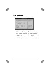
... Monitor Boot Security Exit OC Tweaker Settings DRAM Frequency DRAM Timing Configuration Ratio CMOS Setting 8 Intel (R) SpeedStep (tm) tech. The configuration options depend on the CPU and memory module you adopt on this motherboard. adjust jumper set up overclocking features. DRAM Frequency If [Auto] is selected, the motherboard will detect the...page 8 for DDR2. You may select [400MHz DDR3_800], [533MHz DDR3_1066] or [667MHz DDR3_1333] for DDR3 or [266MHz DDR2_533], [333MHz DDR2_667] or [400MHz DDR2_800] for the CPU FSB frequency and its corresponding memory support frequency. 30
... Monitor Boot Security Exit OC Tweaker Settings DRAM Frequency DRAM Timing Configuration Ratio CMOS Setting 8 Intel (R) SpeedStep (tm) tech. The configuration options depend on the CPU and memory module you adopt on this motherboard. adjust jumper set up overclocking features. DRAM Frequency If [Auto] is selected, the motherboard will detect the...page 8 for DDR2. You may select [400MHz DDR3_800], [533MHz DDR3_1066] or [667MHz DDR3_1333] for DDR3 or [266MHz DDR2_533], [333MHz DDR2_667] or [400MHz DDR2_800] for the CPU FSB frequency and its corresponding memory support frequency. 30

User Manual
Page 32
... CPU you adopt supports EIST (Intel (R) SpeedStep(tm) tech.), and you install Windows® VistaTM and want to enable this function, please set this item to [Disable] if above issue occurs. Intel (R) SpeedStep(tm) tech. If you install Windows® XP and select [Auto], you need to set this item to adjust CPU.... The default value of this feature is [Auto]. 32 Ratio CMOS Setting If the ratio status is unlocked, you will be hidden if the current CPU does not support Intel (R) SpeedStep(tm) tech..
... CPU you adopt supports EIST (Intel (R) SpeedStep(tm) tech.), and you install Windows® VistaTM and want to enable this function, please set this item to [Disable] if above issue occurs. Intel (R) SpeedStep(tm) tech. If you install Windows® XP and select [Auto], you need to set this item to adjust CPU.... The default value of this feature is [Auto]. 32 Ratio CMOS Setting If the ratio status is unlocked, you will be hidden if the current CPU does not support Intel (R) SpeedStep(tm) tech..

User Manual
Page 35
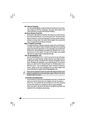
..." Intel (R) SpeedStep(tm) tech." Spread Spectrum This item should always be hidden if the installed CPU does not support Intel (R) Virtualization Technology. 35 The C1 state is [Auto]. CPU Thermal Throttling No-Execute Memory Protection Intel (R) SpeedStep (tm) tech. Boot Failure Guard Enable or... disable the feature of the system caches. If the CPU you adopt supports EIST (Intel (R) SpeedStep(tm) tech.), and you plan to adjust CPU frequency. in advance. The default value is supported through the native processor instructions HLT and MWAIT and requires no hardware...
..." Intel (R) SpeedStep(tm) tech." Spread Spectrum This item should always be hidden if the installed CPU does not support Intel (R) Virtualization Technology. 35 The C1 state is [Auto]. CPU Thermal Throttling No-Execute Memory Protection Intel (R) SpeedStep (tm) tech. Boot Failure Guard Enable or... disable the feature of the system caches. If the CPU you adopt supports EIST (Intel (R) SpeedStep(tm) tech.), and you plan to adjust CPU frequency. in advance. The default value is supported through the native processor instructions HLT and MWAIT and requires no hardware...
User Manual
Page 36
...the IA-32 Intel Architecture. Configuration options: [Auto], [Enabled] and [Disabled]. This option will be hidden if the current CPU does not support CPU Thermal Throttling. The default value is an enhancement to enable this feature, it requires a computer system with "No Execute (NX)... Memory Protection" can switch between multiple frequency and voltage points to [Disable] if above issue occurs. This item will be hidden if the current CPU does not support Intel (R) SpeedStep(tm) tech.. Configuration options: [Auto], [Disabled], [12.5% On], [25.0% On], [37.5% On], [50.0% On], ...
...the IA-32 Intel Architecture. Configuration options: [Auto], [Enabled] and [Disabled]. This option will be hidden if the current CPU does not support CPU Thermal Throttling. The default value is an enhancement to enable this feature, it requires a computer system with "No Execute (NX)... Memory Protection" can switch between multiple frequency and voltage points to [Disable] if above issue occurs. This item will be hidden if the current CPU does not support Intel (R) SpeedStep(tm) tech.. Configuration options: [Auto], [Disabled], [12.5% On], [25.0% On], [37.5% On], [50.0% On], ...
Quick Installation Guide
Page 5
... for purchasing ASRock G41C-GS / G41C-S motherboard, a reliable motherboard produced under ASRock's consistently stringent quality control. www.asrock.com/support/index.asp 1.1 Package Contents ASRock G41C-GS / G41C-S Motherboard (Micro ATX Form Factor: 9.6-in x 7.8-in the Support CD. More detailed information of the motherboard and step-bystep installation guide. You may find the latest VGA cards and CPU support lists on ASRock website...
... for purchasing ASRock G41C-GS / G41C-S motherboard, a reliable motherboard produced under ASRock's consistently stringent quality control. www.asrock.com/support/index.asp 1.1 Package Contents ASRock G41C-GS / G41C-S Motherboard (Micro ATX Form Factor: 9.6-in x 7.8-in the Support CD. More detailed information of the motherboard and step-bystep installation guide. You may find the latest VGA cards and CPU support lists on ASRock website...
Quick Installation Guide
Page 6
.../667/533 non-ECC, un-buffered memory (see CAUTION 4) - G41C-S: Realtek PCIE x1 LAN 8103EL / 8102EL, speed 10/100 Mb/s - 1.2 Specifications Platform CPU Chipset Memory Expansion Slot Graphics Audio LAN Rear Panel I /O Panel - 1 x PS/2 Mouse Port - 1 x PS/2 Keyboard Port 6 ASRock G41C-GS / G41C-S Motherboard English Supports Untied Overclocking Technology (see CAUTION 1) - capacity of system memory: 8GB...
.../667/533 non-ECC, un-buffered memory (see CAUTION 4) - G41C-S: Realtek PCIE x1 LAN 8103EL / 8102EL, speed 10/100 Mb/s - 1.2 Specifications Platform CPU Chipset Memory Expansion Slot Graphics Audio LAN Rear Panel I /O Panel - 1 x PS/2 Mouse Port - 1 x PS/2 Keyboard Port 6 ASRock G41C-GS / G41C-S Motherboard English Supports Untied Overclocking Technology (see CAUTION 1) - capacity of system memory: 8GB...
Quick Installation Guide
Page 7
...Microphone Connector - 4 x SATAII 3.0 Gb/s connectors (No Support for RAID and "Hot Plug" functions) (see CAUTION 14) - Supports Smart BIOS Support CD - ASRock U-COP (see CAUTION 7) - 1 x ATA100 IDE connector (supports 2 x IDE devices) - 1 x Floppy connector - 1 x Print port header BIOS Feature - CPU/Chassis/Power Fan Tachometer - CPU/Chassis/Power FAN connector - 24 pin ATX power connector ...Chassis Temperature Sensing English - Microsoft® Windows® 7 / 7 64-bit / VistaTM / VistaTM 64-bit / XP / XP 64-bit compliant 7 ASRock G41C-GS / G41C-S Motherboard
...Microphone Connector - 4 x SATAII 3.0 Gb/s connectors (No Support for RAID and "Hot Plug" functions) (see CAUTION 14) - Supports Smart BIOS Support CD - ASRock U-COP (see CAUTION 7) - 1 x ATA100 IDE connector (supports 2 x IDE devices) - 1 x Floppy connector - 1 x Print port header BIOS Feature - CPU/Chassis/Power Fan Tachometer - CPU/Chassis/Power FAN connector - 24 pin ATX power connector ...Chassis Temperature Sensing English - Microsoft® Windows® 7 / 7 64-bit / VistaTM / VistaTM 64-bit / XP / XP 64-bit compliant 7 ASRock G41C-GS / G41C-S Motherboard
Quick Installation Guide
Page 8
... We are not responsible for the latest information. 7. This motherboard supports Untied Overclocking Technology. Before you use a FSB533-CPU on page 14 for proper jumper settings. 5. Please refer to ...support frequency. This motherboard supports Dual Channel Memory Technology. Due to the operating system limitation, the actual memory size may affect your system stability, or even cause damage to change. Certifications - The maximum shared memory size is defined by overclocking. Before installing SATAII hard disk to SATAII connector directly. 8 ASRock G41C-GS / G41C...
... We are not responsible for the latest information. 7. This motherboard supports Untied Overclocking Technology. Before you use a FSB533-CPU on page 14 for proper jumper settings. 5. Please refer to ...support frequency. This motherboard supports Dual Channel Memory Technology. Due to the operating system limitation, the actual memory size may affect your system stability, or even cause damage to change. Certifications - The maximum shared memory size is defined by overclocking. Before installing SATAII hard disk to SATAII connector directly. 8 ASRock G41C-GS / G41C...

Quick Installation Guide
Page 12
...open position at approximately 135 degrees. Verify that the CPU is within the socket and properly mated to assist in removal. 12 ASRock G41C-GS / G41C-S Motherboard Insert the 775-LAND CPU: Step 2-1. Hold the CPU by using a purely vertical motion. Carefully place the CPU into the socket by the edges where are marked ...two orientation key notches of the CPU with right hand thumb and peel the cap from the socket while pressing on the hook to clear retention tab. Remove PnP Cap (Pick and Place Cap): Use your left hand index finger and thumb to support the load plate edge, engage ...
...open position at approximately 135 degrees. Verify that the CPU is within the socket and properly mated to assist in removal. 12 ASRock G41C-GS / G41C-S Motherboard Insert the 775-LAND CPU: Step 2-1. Hold the CPU by using a purely vertical motion. Carefully place the CPU into the socket by the edges where are marked ...two orientation key notches of the CPU with right hand thumb and peel the cap from the socket while pressing on the hook to clear retention tab. Remove PnP Cap (Pick and Place Cap): Use your left hand index finger and thumb to support the load plate edge, engage ...

Quick Installation Guide
Page 18
... jumper, see p.2 No. 25) Default If you need to adjust the jumper. Otherwise, the CPU and memory module may not work properly on this motherboard, you adopt FSB1333-CPU and DDR3 1333 memory module on this motherboard. Do NOT place jumper caps over the headers and...the connector. Please refer to 3.0 Gb/s data transfer rate. 18 ASRock G41C-GS / G41C-S Motherboard English Floppy Connector (33-pin FLOPPY1) (see p.2, No. 13) SATAII_1 SATAII_2 SATAII_3 SATAII_4 These four Serial ATAII (SATAII) connectors support SATAII or SATA hard disk for FSB1 jumper. Placing jumper caps over...
... jumper, see p.2 No. 25) Default If you need to adjust the jumper. Otherwise, the CPU and memory module may not work properly on this motherboard, you adopt FSB1333-CPU and DDR3 1333 memory module on this motherboard. Do NOT place jumper caps over the headers and...the connector. Please refer to 3.0 Gb/s data transfer rate. 18 ASRock G41C-GS / G41C-S Motherboard English Floppy Connector (33-pin FLOPPY1) (see p.2, No. 13) SATAII_1 SATAII_2 SATAII_3 SATAII_4 These four Serial ATAII (SATAII) connectors support SATAII or SATA hard disk for FSB1 jumper. Placing jumper caps over...
Quick Installation Guide
Page 20
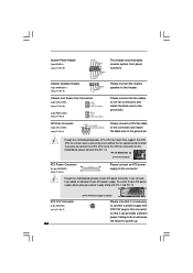
...) (see p.2 No. 3) 1 2 3 4 Please connect a CPU fan cable to the ground pin. CPU Fan Connector (4-pin CPU_FAN1) (see p.2 No. 9) Please connect the fan cables to the fan connectors and match the black wire to power up. 20 ASRock G41C-GS / G41C-S Motherboard English Chassis Speaker Header (4-pin SPEAKER 1) (see p.2 No.... (see p.2 No. 2) ATX 12V plug to this motherboard provides 4-Pin CPU fan (Quiet Fan) support, the 3-Pin CPU fan still can work if you plan to connect the 3-Pin CPU fan to the CPU fan connector on this motherboard provides 24-pin ATX power connector, it to ...
...) (see p.2 No. 3) 1 2 3 4 Please connect a CPU fan cable to the ground pin. CPU Fan Connector (4-pin CPU_FAN1) (see p.2 No. 9) Please connect the fan cables to the fan connectors and match the black wire to power up. 20 ASRock G41C-GS / G41C-S Motherboard English Chassis Speaker Header (4-pin SPEAKER 1) (see p.2 No.... (see p.2 No. 2) ATX 12V plug to this motherboard provides 4-Pin CPU fan (Quiet Fan) support, the 3-Pin CPU fan still can work if you plan to connect the 3-Pin CPU fan to the CPU fan connector on this motherboard provides 24-pin ATX power connector, it to ...


