
User Manual
Page 10
... USB3 ATX12V1 USB 2.0 T: USB0 B: USB1 Top: RJ-45 1 OC 800 1 FSB0 1 FSB1 Intel G31 Chipset LPT1 1 LAN PHY PCIE1 CMOS Battery CLRCMOS1 IDE1 Super IO CD1 RoHS AUDIO CODEC HD_AUDIO1 FLOPPY1 1 21 20 PCIE2 SATAII_3 PCI1 Intel ICH7 PCI2 CHA_FAN1 4Mb BIOS PANEL 1 PLED PWRBTN... 1 HDLED RESET USB4_5 1 USB6_7 1 SPEAKER1 1 SATAII_1 19 18 17 16 15 14 13 12 SATAII_2 SATAII_4 6 7 8 9 10 11 1 PS2_USB_PWR1 Jumper 15 USB...
... USB3 ATX12V1 USB 2.0 T: USB0 B: USB1 Top: RJ-45 1 OC 800 1 FSB0 1 FSB1 Intel G31 Chipset LPT1 1 LAN PHY PCIE1 CMOS Battery CLRCMOS1 IDE1 Super IO CD1 RoHS AUDIO CODEC HD_AUDIO1 FLOPPY1 1 21 20 PCIE2 SATAII_3 PCI1 Intel ICH7 PCI2 CHA_FAN1 4Mb BIOS PANEL 1 PLED PWRBTN... 1 HDLED RESET USB4_5 1 USB6_7 1 SPEAKER1 1 SATAII_1 19 18 17 16 15 14 13 12 SATAII_2 SATAII_4 6 7 8 9 10 11 1 PS2_USB_PWR1 Jumper 15 USB...

User Manual
Page 18
... +5VSB (standby) for PS/2 +5V +5VSB or USB wake up events. Clear CMOS (CLRCMOS1, 2-pin jumper) (see p.10 No. 1) 2_3 Short pin2, pin3 to clear the data in CMOS includes system setup information such as system password, date, time, and system setup parameters.... The illustration shows a 3-pin jumper whose pin1 and pin2 are setup. After waiting for 5 seconds. 18 Note: To select +5VSB, it requires 2 Amp and higher standby current provided by power supply. To clear and reset...
... +5VSB (standby) for PS/2 +5V +5VSB or USB wake up events. Clear CMOS (CLRCMOS1, 2-pin jumper) (see p.10 No. 1) 2_3 Short pin2, pin3 to clear the data in CMOS includes system setup information such as system password, date, time, and system setup parameters.... The illustration shows a 3-pin jumper whose pin1 and pin2 are setup. After waiting for 5 seconds. 18 Note: To select +5VSB, it requires 2 Amp and higher standby current provided by power supply. To clear and reset...
User Manual (VIA)
Page 10
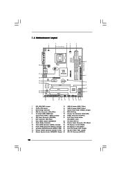
...Floppy Connector (FLOPPY1) 6 ATX Power Connector (ATXPWR1) 21 Front Panel Audio Header 7 IDE1 Connector (IDE1, Blue) (HD_AUDIO1, Lime) 8 Clear CMOS Jumper (CLRCMOS1) 22 PCI Slots (PCI1- 2) 9 South Bridge Controller 23 Internal Audio Connector: CD1 (Black) 10 Third SATAII Connector (SATAII_3; Orange... Super IO CD1 RoHS AUDIO CODEC HD_AUDIO1 FLOPPY1 1 21 20 PCIE2 SATAII_3 PCI1 Intel ICH7 PCI2 CHA_FAN1 4Mb BIOS PANEL 1 PLED PWRBTN 1 HDLED RESET USB4_5 1 USB6_7 1 SPEAKER1 1 SATAII_1 19 18 17 16 15 14 13 12 SATAII_2 SATAII_4 6 7 8 9 10 11 1 PS2_USB_PWR1 Jumper ...
...Floppy Connector (FLOPPY1) 6 ATX Power Connector (ATXPWR1) 21 Front Panel Audio Header 7 IDE1 Connector (IDE1, Blue) (HD_AUDIO1, Lime) 8 Clear CMOS Jumper (CLRCMOS1) 22 PCI Slots (PCI1- 2) 9 South Bridge Controller 23 Internal Audio Connector: CD1 (Black) 10 Third SATAII Connector (SATAII_3; Orange... Super IO CD1 RoHS AUDIO CODEC HD_AUDIO1 FLOPPY1 1 21 20 PCIE2 SATAII_3 PCI1 Intel ICH7 PCI2 CHA_FAN1 4Mb BIOS PANEL 1 PLED PWRBTN 1 HDLED RESET USB4_5 1 USB6_7 1 SPEAKER1 1 SATAII_1 19 18 17 16 15 14 13 12 SATAII_2 SATAII_4 6 7 8 9 10 11 1 PS2_USB_PWR1 Jumper ...
User Manual (VIA)
Page 18
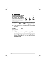
...2-pin jumper Note: CLRCMOS1 allows you to enable +5VSB (standby) for PS/2 +5V +5VSB or USB wake up events. The data in CMOS. To clear and reset the system parameters to short 2 pins on pins, the jumper is placed on these 2 pins. The illustration shows a 3-pin jumper whose pin1...to default setup, please turn off the computer and unplug the power cord from the power supply. Clear CMOS (CLRCMOS1, 2-pin jumper) (see p.10 No. 1) 2_3 Short pin2, pin3 to clear the data in CMOS includes system setup information such as system password, date, time, and system setup parameters.
...2-pin jumper Note: CLRCMOS1 allows you to enable +5VSB (standby) for PS/2 +5V +5VSB or USB wake up events. The data in CMOS. To clear and reset the system parameters to short 2 pins on pins, the jumper is placed on these 2 pins. The illustration shows a 3-pin jumper whose pin1...to default setup, please turn off the computer and unplug the power cord from the power supply. Clear CMOS (CLRCMOS1, 2-pin jumper) (see p.10 No. 1) 2_3 Short pin2, pin3 to clear the data in CMOS includes system setup information such as system password, date, time, and system setup parameters.
Quick Installation Guide
Page 14
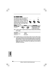
... the power cord from the power supply. After waiting for PS/2 or USB wake up events. The data in CMOS. When the jumper cap is placed on these 2 pins. To clear and reset the system parameters to short 2 pins on pins, the jumper is "Open". The illustration shows a 3-pin jumper whose pin1... supply. 2.5 Jumpers Setup The illustration shows how jumpers are "Short" when jumper cap is Short Open placed on pins, the jumper is "Short". English 14 ASRock G31M-GS / G31M-S Motherboard
... the power cord from the power supply. After waiting for PS/2 or USB wake up events. The data in CMOS. When the jumper cap is placed on these 2 pins. To clear and reset the system parameters to short 2 pins on pins, the jumper is "Open". The illustration shows a 3-pin jumper whose pin1... supply. 2.5 Jumpers Setup The illustration shows how jumpers are "Short" when jumper cap is Short Open placed on pins, the jumper is "Short". English 14 ASRock G31M-GS / G31M-S Motherboard

