User Manual
Page 3
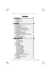
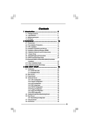
... (SATA) / Serial ATAII (SATAII) Hard Disks Installation 25 2.11 Driver Installation Guide 25 2.12 Untied Overclocking Technology 25 3 BIOS SETUP UTILITY 26 3.1 Introduction 26 3.1.1 BIOS Menu Bar 26 3.1.2 Navigation Keys 27 3.2 Main Screen 27 3.3 Smart Screen 29 3.4 Advanced Screen 30 3.4.1 CPU Configuration 30 3.4.2 Chipset Configuration 32 3.4.3 ACPI Configuration 35 3.4.4 IDE Configuration 36 3.4.5 PCIPnP Configuration 38 3.4.6 Floppy Configuration 39 3.4.7 Super IO Configuration 39 3.4.8 USB Configuration 40 3.5 Hardware Health Event Monitoring Screen 41 3.6 Boot Screen...
... (SATA) / Serial ATAII (SATAII) Hard Disks Installation 25 2.11 Driver Installation Guide 25 2.12 Untied Overclocking Technology 25 3 BIOS SETUP UTILITY 26 3.1 Introduction 26 3.1.1 BIOS Menu Bar 26 3.1.2 Navigation Keys 27 3.2 Main Screen 27 3.3 Smart Screen 29 3.4 Advanced Screen 30 3.4.1 CPU Configuration 30 3.4.2 Chipset Configuration 32 3.4.3 ACPI Configuration 35 3.4.4 IDE Configuration 36 3.4.5 PCIPnP Configuration 38 3.4.6 Floppy Configuration 39 3.4.7 Super IO Configuration 39 3.4.8 USB Configuration 40 3.5 Hardware Health Event Monitoring Screen 41 3.6 Boot Screen...

User Manual
Page 7
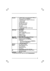
... - Chassis Temperature Sensing - CPU Quiet Fan - Voltage Monitoring: +12V, +5V, +3.3V, Vcore OS - CD in header - ACPI 1.1 Compliance Wake Up Events - Supports jumperfree - Supports Smart BIOS Support CD - Hybrid Booster: - Boot Failure Guard (B.F.G.) Hardware - Connector - 4 x SATAII 3.0 Gb/s connectors (No Support for RAID and "Hot Plug" functions) (see CAUTION 12) - Front panel audio connector - 2 x USB 2.0 headers (support 4 USB 2.0 ports) (see CAUTION 10) - CPU Fan Tachometer - AMI Legal BIOS - Drivers, Utilities, AntiVirus Software (Trial Version...
... - Chassis Temperature Sensing - CPU Quiet Fan - Voltage Monitoring: +12V, +5V, +3.3V, Vcore OS - CD in header - ACPI 1.1 Compliance Wake Up Events - Supports jumperfree - Supports Smart BIOS Support CD - Hybrid Booster: - Boot Failure Guard (B.F.G.) Hardware - Connector - 4 x SATAII 3.0 Gb/s connectors (No Support for RAID and "Hot Plug" functions) (see CAUTION 12) - Front panel audio connector - 2 x USB 2.0 headers (support 4 USB 2.0 ports) (see CAUTION 10) - CPU Fan Tachometer - AMI Legal BIOS - Drivers, Utilities, AntiVirus Software (Trial Version...
User Manual
Page 10
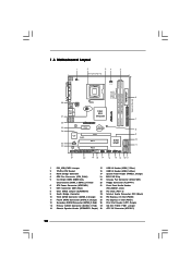
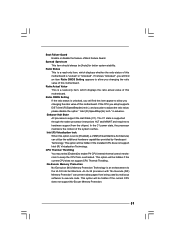
...16 USB 2.0 Header (USB4_5, Blue) 3 North Bridge Controller 17 System Panel Header (PANEL1, Orange) 4 CPU Fan Connector (CPU_FAN1) 18 BIOS SPI Chip 5 2 x 240-pin DDR2 DIMM Slots 19 Chassis Fan Connector (CHA_FAN1) (Dual Channel: DDRII_1, DDRII_2; Yellow) 20 Floppy Connector (FLOPPY1) 6 ATX Power Connector (ATXPWR1) 21 Front Panel Audio Header 7 IDE1 Connector (IDE1, Blue) (HD_AUDIO1, Lime) 8 Clear CMOS Jumper (CLRCMOS1) 22 PCI Slots (PCI1- 2) 9 South Bridge Controller 23 Internal Audio Connector: CD1 (Black) 10 Third SATAII Connector (SATAII_3; Orange) 25 PCI Express x1...
...16 USB 2.0 Header (USB4_5, Blue) 3 North Bridge Controller 17 System Panel Header (PANEL1, Orange) 4 CPU Fan Connector (CPU_FAN1) 18 BIOS SPI Chip 5 2 x 240-pin DDR2 DIMM Slots 19 Chassis Fan Connector (CHA_FAN1) (Dual Channel: DDRII_1, DDRII_2; Yellow) 20 Floppy Connector (FLOPPY1) 6 ATX Power Connector (ATXPWR1) 21 Front Panel Audio Header 7 IDE1 Connector (IDE1, Blue) (HD_AUDIO1, Lime) 8 Clear CMOS Jumper (CLRCMOS1) 22 PCI Slots (PCI1- 2) 9 South Bridge Controller 23 Internal Audio Connector: CD1 (Black) 10 Third SATAII Connector (SATAII_3; Orange) 25 PCI Express x1...
User Manual
Page 25
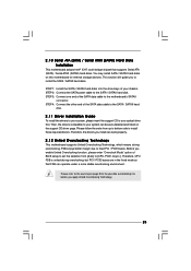
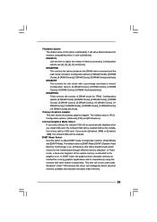
... Untied Overclocking Technology. 25 Then, the drivers compatible to your system can be auto-detected and listed on this motherboard for the possible overclocking risk before you enable Untied Overclocking function, please enter "Overclock Mode" option of the SATA data cable to your chassis. 2 . 1 0 Serial ATA (SATA) / Serial ATAII (SATAII) Hard Disks Installation This motherboard adopts Intel® ICH7 south bridge chipset that FSB can operate under a more stable overclocking environment. STEP 3: Connect one end of BIOS setup to set...
... Untied Overclocking Technology. 25 Then, the drivers compatible to your system can be auto-detected and listed on this motherboard for the possible overclocking risk before you enable Untied Overclocking function, please enter "Overclock Mode" option of the SATA data cable to your chassis. 2 . 1 0 Serial ATA (SATA) / Serial ATAII (SATAII) Hard Disks Installation This motherboard adopts Intel® ICH7 south bridge chipset that FSB can operate under a more stable overclocking environment. STEP 3: Connect one end of BIOS setup to set...
User Manual
Page 31
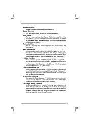
... disable the option " Intel (R) SpeedStep(tm) tech." This option will find an item Ratio CMOS Setting appears to allow you changing the ratio value of this motherboard. Spread Spectrum This item should always be hidden if the installed CPU does not support Intel (R) Virtualization Technology. CPU Thermal Throttling You may select [Enabled] to enable P4 CPU internal thermal control mechanism to execute code. Intel (R) Virtualization tech. Enhance Halt State All processors support...
... disable the option " Intel (R) SpeedStep(tm) tech." This option will find an item Ratio CMOS Setting appears to allow you changing the ratio value of this motherboard. Spread Spectrum This item should always be hidden if the installed CPU does not support Intel (R) Virtualization Technology. CPU Thermal Throttling You may select [Enabled] to enable P4 CPU internal thermal control mechanism to execute code. Intel (R) Virtualization tech. Enhance Halt State All processors support...
User Manual
Page 32
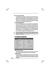
...above issue occurs. 3.4.2 Chipset Configuration BIOS SETUP UTILITY Advanced Chipset Configuration Memory Remap Feature DRAM Frequency Flexibility Option DRAM tCL DRAM tRCD DRAM tRP DRAM tRAS [Disabled] [Auto] [Disabled] [Auto] [Auto] [Auto] [Auto] Primary Graphics Adapter Internal Graphics Mode Select DVMT Mode Select DVMT/FIXED Memory [PCI] [Auto] [DVMT Mode] [256MB] OnBoard HD Audio Front Panel OnBoard Lan [Auto] [Auto] [Enabled] DRAM Voltage [Auto] ENABLE: Allow remapping of memory. +F1 F9 F10 ESC Select Screen Select Item Change Option General Help Load Defaults Save and Exit...
...above issue occurs. 3.4.2 Chipset Configuration BIOS SETUP UTILITY Advanced Chipset Configuration Memory Remap Feature DRAM Frequency Flexibility Option DRAM tCL DRAM tRCD DRAM tRP DRAM tRAS [Disabled] [Auto] [Disabled] [Auto] [Auto] [Auto] [Auto] Primary Graphics Adapter Internal Graphics Mode Select DVMT Mode Select DVMT/FIXED Memory [PCI] [Auto] [DVMT Mode] [256MB] OnBoard HD Audio Front Panel OnBoard Lan [Auto] [Auto] [Enabled] DRAM Voltage [Auto] ENABLE: Allow remapping of memory. +F1 F9 F10 ESC Select Screen Select Item Change Option General Help Load Defaults Save and Exit...

User Manual
Page 33
... using this option is [Disabled]. Configuration options: [2 DRAM Clocks], [3 DRAM Clocks], [4 DRAM Clocks], [5 DRAM Clocks], [6 DRAM Clocks] and [Auto]. DRAM tRCD This controls the latency between the DRAM active command and the read / write command. Internal Graphics Mode Select If you select [Auto], the onboard VGA will be enabled without the installation of any add-on VGA card. In Fixed mode, a fixed-size fragment of the system memory is issued. DRAM tRAS Thhis controls the number of DRAM clocks for the motherboard through efficient memory utilization. DRAM tRP This controls...
... using this option is [Disabled]. Configuration options: [2 DRAM Clocks], [3 DRAM Clocks], [4 DRAM Clocks], [5 DRAM Clocks], [6 DRAM Clocks] and [Auto]. DRAM tRCD This controls the latency between the DRAM active command and the read / write command. Internal Graphics Mode Select If you select [Auto], the onboard VGA will be enabled without the installation of any add-on VGA card. In Fixed mode, a fixed-size fragment of the system memory is issued. DRAM tRAS Thhis controls the number of DRAM clocks for the motherboard through efficient memory utilization. DRAM tRP This controls...
User Manual
Page 40
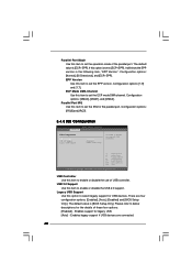
... enable or disable the use of the parallel port. Enables support for USB devices. If this option is set the ECP mode DMA channel. Legacy USB Support Use this option to select legacy support for legacy USB. [Auto] - EPP Version Use this item to set the operation mode of USB controller. The default value is [BIOS Setup Only]. Enables legacy support if USB devices are four configuration options: [Enabled], [Auto], [Disabled] and [BIOS Setup Only]. USB Controller Use this item to enable or disable the USB 2.0 support. Configuration options: [1.9] and [1.7]. There are connected...
... enable or disable the use of the parallel port. Enables support for USB devices. If this option is set the ECP mode DMA channel. Legacy USB Support Use this option to select legacy support for legacy USB. [Auto] - EPP Version Use this item to set the operation mode of USB controller. The default value is [BIOS Setup Only]. Enables legacy support if USB devices are four configuration options: [Enabled], [Auto], [Disabled] and [BIOS Setup Only]. USB Controller Use this item to enable or disable the USB 2.0 support. Configuration options: [1.9] and [1.7]. There are connected...
User Manual
Page 43
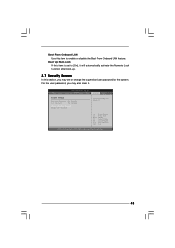
... Lock function after boot-up. 3.7 Security Screen In this item is set to enable or disable the Boot From Onboard LAN feature. BIOS SETUP UTILITY Main Smart Advanced H/W Monitor Boot Security Exit Security Settings Supervisor Password : Not Installed User Password : Not Installed Change Supervisor Password Change User Password Install or Change the password. Select Screen Select Item Enter Change F1 General Help F9 Load Defaults F10 Save and Exit ESC Exit v02.54 (C) Copyright 1985-2005, American Megatrends, Inc. 43 Boot From Onboard LAN Use this item to...
... Lock function after boot-up. 3.7 Security Screen In this item is set to enable or disable the Boot From Onboard LAN feature. BIOS SETUP UTILITY Main Smart Advanced H/W Monitor Boot Security Exit Security Settings Supervisor Password : Not Installed User Password : Not Installed Change Supervisor Password Change User Password Install or Change the password. Select Screen Select Item Enter Change F1 General Help F9 Load Defaults F10 Save and Exit ESC Exit v02.54 (C) Copyright 1985-2005, American Megatrends, Inc. 43 Boot From Onboard LAN Use this item to...

User Manual
Page 45
Chapter 4 Software Support 4.1 Install Operating System This motherboard supports various Microsoft® Windows® operating systems: 2000 / XP / XP 64-bit / VistaTM / VistaTM 64-bit. Because motherboard settings and hardware options vary, use the setup procedures in this chapter for more about ASRock, welcome to install it. 4.2.4 Contact Information If you may contact your computer. If the Main Menu did not appear automatically, locate and double click on a specific item...
Chapter 4 Software Support 4.1 Install Operating System This motherboard supports various Microsoft® Windows® operating systems: 2000 / XP / XP 64-bit / VistaTM / VistaTM 64-bit. Because motherboard settings and hardware options vary, use the setup procedures in this chapter for more about ASRock, welcome to install it. 4.2.4 Contact Information If you may contact your computer. If the Main Menu did not appear automatically, locate and double click on a specific item...
User Manual (VIA)
Page 3
... (SATA) / Serial ATAII (SATAII) Hard Disks Installation 25 2.11 Driver Installation Guide 25 2.12 Untied Overclocking Technology 25 3 BIOS SETUP UTILITY 26 3.1 Introduction 26 3.1.1 BIOS Menu Bar 26 3.1.2 Navigation Keys 27 3.2 Main Screen 27 3.3 Smart Screen 29 3.4 Advanced Screen 30 3.4.1 CPU Configuration 30 3.4.2 Chipset Configuration 32 3.4.3 ACPI Configuration 35 3.4.4 IDE Configuration 36 3.4.5 PCIPnP Configuration 38 3.4.6 Floppy Configuration 39 3.4.7 Super IO Configuration 39 3.4.8 USB Configuration 40 3.5 Hardware Health Event Monitoring Screen 41 3.6 Boot Screen...
... (SATA) / Serial ATAII (SATAII) Hard Disks Installation 25 2.11 Driver Installation Guide 25 2.12 Untied Overclocking Technology 25 3 BIOS SETUP UTILITY 26 3.1 Introduction 26 3.1.1 BIOS Menu Bar 26 3.1.2 Navigation Keys 27 3.2 Main Screen 27 3.3 Smart Screen 29 3.4 Advanced Screen 30 3.4.1 CPU Configuration 30 3.4.2 Chipset Configuration 32 3.4.3 ACPI Configuration 35 3.4.4 IDE Configuration 36 3.4.5 PCIPnP Configuration 38 3.4.6 Floppy Configuration 39 3.4.7 Super IO Configuration 39 3.4.8 USB Configuration 40 3.5 Hardware Health Event Monitoring Screen 41 3.6 Boot Screen...
User Manual (VIA)
Page 7
...ASRock U-COP (see CAUTION 10) - Voltage Monitoring: +12V, +5V, +3.3V, Vcore OS - Chassis Temperature Sensing - CPU Frequency Stepless Control (see CAUTION 8) - 1 x ATA100 IDE connector (supports 2 x IDE devices) - 1 x Floppy connector - 1 x Print port header - Connector - 4 x SATAII 3.0 Gb/s connectors (No Support for RAID and "Hot Plug" functions) (see CAUTION 12) - Supports jumperfree - Supports Smart BIOS Support CD - ACPI 1.1 Compliance Wake Up Events - CD in header - AMI Legal BIOS - Hybrid Booster: - Front panel audio connector - 2 x USB...
...ASRock U-COP (see CAUTION 10) - Voltage Monitoring: +12V, +5V, +3.3V, Vcore OS - Chassis Temperature Sensing - CPU Frequency Stepless Control (see CAUTION 8) - 1 x ATA100 IDE connector (supports 2 x IDE devices) - 1 x Floppy connector - 1 x Print port header - Connector - 4 x SATAII 3.0 Gb/s connectors (No Support for RAID and "Hot Plug" functions) (see CAUTION 12) - Supports jumperfree - Supports Smart BIOS Support CD - ACPI 1.1 Compliance Wake Up Events - CD in header - AMI Legal BIOS - Hybrid Booster: - Front panel audio connector - 2 x USB...

User Manual (VIA)
Page 25
... hard disks into the drive bays of the SATA data cable to the warning on this motherboard for the possible overclocking risk before you enable Untied Overclocking function, please enter "Overclock Mode" option of the SATA data cable to the SATA / SATAII hard disk. 2.11 Driver Installation Guide To install the drivers to your system, please insert the support CD to [CPU, PCIE, Async.]. You may install SATA / SATAII hard disks on page 8 for internal storage devices. STEP 4: Connect the other end of BIOS setup to set...
... hard disks into the drive bays of the SATA data cable to the warning on this motherboard for the possible overclocking risk before you enable Untied Overclocking function, please enter "Overclock Mode" option of the SATA data cable to the SATA / SATAII hard disk. 2.11 Driver Installation Guide To install the drivers to your system, please insert the support CD to [CPU, PCIE, Async.]. You may install SATA / SATAII hard disks on page 8 for internal storage devices. STEP 4: Connect the other end of BIOS setup to set...
User Manual (VIA)
Page 31
...-32 Intel Architecture. In the C1 power state, the processor maintains the context of Boot Failure Guard. No-Excute Memory Protection No-Execution (NX) Memory Protection Technology is set to [Enabled], a VMM (Virtual Machine Architecture) can prevent data pages from being used by Vanderpool Technology. This option will be hidden if the installed CPU does not support Intel (R) Virtualization Technology. Boot Failure Guard Enable or disable the feature of the system caches...
...-32 Intel Architecture. In the C1 power state, the processor maintains the context of Boot Failure Guard. No-Excute Memory Protection No-Execution (NX) Memory Protection Technology is set to [Enabled], a VMM (Virtual Machine Architecture) can prevent data pages from being used by Vanderpool Technology. This option will be hidden if the installed CPU does not support Intel (R) Virtualization Technology. Boot Failure Guard Enable or disable the feature of the system caches...

User Manual (VIA)
Page 32
... Feature Use this item to [Disable] if above issue occurs. 3.4.2 Chipset Configuration BIOS SETUP UTILITY Advanced Chipset Configuration Memory Remap Feature DRAM Frequency Flexibility Option DRAM tCL DRAM tRCD DRAM tRP DRAM tRAS [Disabled] [Auto] [Disabled] [Auto] [Auto] [Auto] [Auto] Primary Graphics Adapter Internal Graphics Mode Select DVMT Mode Select DVMT/FIXED Memory [PCI] [Auto] [DVMT Mode] [256MB] OnBoard HD Audio Front Panel OnBoard Lan [Auto] [Auto] [Enabled] DRAM Voltage [Auto] ENABLE: Allow remapping of memory. +F1 F9 F10 ESC Select Screen Select Item Change Option...
... Feature Use this item to [Disable] if above issue occurs. 3.4.2 Chipset Configuration BIOS SETUP UTILITY Advanced Chipset Configuration Memory Remap Feature DRAM Frequency Flexibility Option DRAM tCL DRAM tRCD DRAM tRP DRAM tRAS [Disabled] [Auto] [Disabled] [Auto] [Auto] [Auto] [Auto] Primary Graphics Adapter Internal Graphics Mode Select DVMT Mode Select DVMT/FIXED Memory [PCI] [Auto] [DVMT Mode] [256MB] OnBoard HD Audio Front Panel OnBoard Lan [Auto] [Auto] [Enabled] DRAM Voltage [Auto] ENABLE: Allow remapping of memory. +F1 F9 F10 ESC Select Screen Select Item Change Option...
User Manual (VIA)
Page 33
...[Auto]. Configuration options: [2 DRAM Clocks], [3 DRAM Clocks], [4 DRAM Clocks], [5 DRAM Clocks], [6 DRAM Clocks] and [Auto]. Internal Graphics Mode Select If you select [Auto], the onboard VGA will be used under Windows® VistaTM OS because the driver will not be automatically disabled when you select [Enabled, 8MB] or [Enabled, 1MB], the onboard VGA will be enabled. Configuration options: [Fixed Mode] and [DVMT Mode]. DRAM tRCD This controls the latency between the DRAM active command and the read / write command. In Fixed mode, a fixed-size fragment of the system memory...
...[Auto]. Configuration options: [2 DRAM Clocks], [3 DRAM Clocks], [4 DRAM Clocks], [5 DRAM Clocks], [6 DRAM Clocks] and [Auto]. Internal Graphics Mode Select If you select [Auto], the onboard VGA will be used under Windows® VistaTM OS because the driver will not be automatically disabled when you select [Enabled, 8MB] or [Enabled, 1MB], the onboard VGA will be enabled. Configuration options: [Fixed Mode] and [DVMT Mode]. DRAM tRCD This controls the latency between the DRAM active command and the read / write command. In Fixed mode, a fixed-size fragment of the system memory...

User Manual (VIA)
Page 40
...SETUP UTILITY Advanced USB Configuration USB Controller USB 2.0 Support Legacy USB Support [Enabled] [Enabled] [BIOS Setup Only] To enable or disable the onboard USB controllers. +F1 F9 F10 ESC Select Screen Select Item Change Option General Help Load Defaults Save and Exit Exit v02.54 (C) Copyright 1985-2005, American Megatrends, Inc. Configuration options: [1.9] and [1.7]. Enables support for the details of the parallel port. Please refer to below descriptions for legacy USB. [Auto] - EPP Version Use this item to enable or disable the USB 2.0 support. Legacy USB Support...
...SETUP UTILITY Advanced USB Configuration USB Controller USB 2.0 Support Legacy USB Support [Enabled] [Enabled] [BIOS Setup Only] To enable or disable the onboard USB controllers. +F1 F9 F10 ESC Select Screen Select Item Change Option General Help Load Defaults Save and Exit Exit v02.54 (C) Copyright 1985-2005, American Megatrends, Inc. Configuration options: [1.9] and [1.7]. Enables support for the details of the parallel port. Please refer to below descriptions for legacy USB. [Auto] - EPP Version Use this item to enable or disable the USB 2.0 support. Legacy USB Support...
User Manual (VIA)
Page 45
...; Refer to display the menus. 4.2.2 Drivers Menu The Drivers Menu shows the available devices drivers if the system detects installed devices. The CD automatically displays the Main Menu if "AUTORUN" is enabled in the Support CD to your CD-ROM drive. Because motherboard settings and hardware options vary, use the setup procedures in this chapter for more about ASRock, welcome to activate the devices. 4.2.3 Utilities Menu The Utilities Menu shows the applications software that enhance the motherboard features. 4.2.1 Running...
...; Refer to display the menus. 4.2.2 Drivers Menu The Drivers Menu shows the available devices drivers if the system detects installed devices. The CD automatically displays the Main Menu if "AUTORUN" is enabled in the Support CD to your CD-ROM drive. Because motherboard settings and hardware options vary, use the setup procedures in this chapter for more about ASRock, welcome to activate the devices. 4.2.3 Utilities Menu The Utilities Menu shows the applications software that enhance the motherboard features. 4.2.1 Running...

Quick Installation Guide
Page 6
... 6 ASRock G31M-GS / G31M-S Motherboard Front panel audio connector - 2 x USB 2.0 headers (support 4 USB 2.0 ports) (see CAUTION 11) - Supports Smart BIOS Support CD - Hybrid Booster: - Drivers, Utilities, AntiVirus Software (Trial Version) Unique Feature - CPU Quiet Fan - CPU/Chassis FAN connector - 24 pin ATX power connector - 4 pin 12V power connector - CPU Fan Tachometer - Intelligent Energy Saver (see CAUTION 9) BIOS Feature - 4Mb AMI BIOS - Boot Failure Guard (B.F.G.) Hardware - AMBIOS 2.3.1 Support - Microsoft® Windows® 2000 / XP / XP 64-bit...
... 6 ASRock G31M-GS / G31M-S Motherboard Front panel audio connector - 2 x USB 2.0 headers (support 4 USB 2.0 ports) (see CAUTION 11) - Supports Smart BIOS Support CD - Hybrid Booster: - Drivers, Utilities, AntiVirus Software (Trial Version) Unique Feature - CPU Quiet Fan - CPU/Chassis FAN connector - 24 pin ATX power connector - 4 pin 12V power connector - CPU Fan Tachometer - Intelligent Energy Saver (see CAUTION 9) BIOS Feature - 4Mb AMI BIOS - Boot Failure Guard (B.F.G.) Hardware - AMBIOS 2.3.1 Support - Microsoft® Windows® 2000 / XP / XP 64-bit...
Quick Installation Guide
Page 20
... guide you apply Untied Overclocking Technology. 20 ASRock G31M-GS / G31M-S Motherboard English Before you install can work properly. 2 . 9 Untied Overclocking Technology This motherboard supports Untied Overclocking Technology, which means during overclocking, but PCI / PCIE buses are in the fixed mode so that supports Serial ATA (SATA) / Serial ATAII (SATAII) hard disks. Please refer to your chassis. STEP 2: Connect the SATA power cable to install the SATA / SATAII hard disks. Therefore, the drivers you enable Untied Overclocking function, please enter "Overclock Mode" option...
... guide you apply Untied Overclocking Technology. 20 ASRock G31M-GS / G31M-S Motherboard English Before you install can work properly. 2 . 9 Untied Overclocking Technology This motherboard supports Untied Overclocking Technology, which means during overclocking, but PCI / PCIE buses are in the fixed mode so that supports Serial ATA (SATA) / Serial ATAII (SATAII) hard disks. Please refer to your chassis. STEP 2: Connect the SATA power cable to install the SATA / SATAII hard disks. Therefore, the drivers you enable Untied Overclocking function, please enter "Overclock Mode" option...


