User Manual
Page 2
...or implied, including but not limited to change without intent to the contents of this manual may or may appear in this motherboard contains Perchlorate, a toxic substance controlled in advance. When you discard the Lithium battery in California, USA, please follow the ...related regulations in Perchlorate Best Management Practices (BMP) regulations passed by ASRock. "Perchlorate Material-special handling may cause undesired operation. In no responsibility for loss of profits, loss of business, loss of ...
...or implied, including but not limited to change without intent to the contents of this manual may or may appear in this motherboard contains Perchlorate, a toxic substance controlled in advance. When you discard the Lithium battery in California, USA, please follow the ...related regulations in Perchlorate Best Management Practices (BMP) regulations passed by ASRock. "Perchlorate Material-special handling may cause undesired operation. In no responsibility for loss of profits, loss of business, loss of ...
User Manual
Page 3
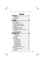
Contents 1 Introduction 5 1.1 Package Contents 5 1.2 Specifications 6 1.3 Motherboard Layout 10 1.4 I/O Panel 11 2 Installation 12 2.1 Screw Holes 12 2.2 Pre-installation Precautions 12 2.3 CPU Installation 13 2.4 Installation of Heatsink and CPU fan 15 2.5 Installation of ...
Contents 1 Introduction 5 1.1 Package Contents 5 1.2 Specifications 6 1.3 Motherboard Layout 10 1.4 I/O Panel 11 2 Installation 12 2.1 Screw Holes 12 2.2 Pre-installation Precautions 12 2.3 CPU Installation 13 2.4 Installation of Heatsink and CPU fan 15 2.5 Installation of ...
User Manual
Page 5
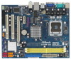
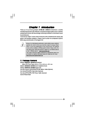
... and the BIOS software might be subject to quality and endurance. www.asrock.com/support/index.asp 1.1 Package Contents ASRock G31M-GS / G31M-S Motherboard (Micro ATX Form Factor: 9.6-in x 7.5-in, 24.4 cm x 19.1 cm) ASRock G31M-GS / G31M-S Quick Installation Guide ASRock G31M-GS / G31M-S Support CD One 80-conductor Ultra ATA 66/100 IDE Ribbon Cable (Optional) One Serial ATA (SATA) Data Cable...
... and the BIOS software might be subject to quality and endurance. www.asrock.com/support/index.asp 1.1 Package Contents ASRock G31M-GS / G31M-S Motherboard (Micro ATX Form Factor: 9.6-in x 7.5-in, 24.4 cm x 19.1 cm) ASRock G31M-GS / G31M-S Quick Installation Guide ASRock G31M-GS / G31M-S Support CD One 80-conductor Ultra ATA 66/100 IDE Ribbon Cable (Optional) One Serial ATA (SATA) Data Cable...
User Manual
Page 8
... 24 to adjust your SATAII hard disk drive to the operating system limitation, the actual memory size may affect your system. This motherboard supports Untied Overclocking Technology. For Windows® XP 64-bit and Windows® VistaTM 64- bit with overclocking, including adjusting the... DDR2 800 800 DDR2 667, DDR2 800 6. About the setting of ASRock OC Tuner. The maximum shared memory size is defined by hardware monitor function and overclock your own risk and expense. This motherboard supports Dual Channel Memory Technology. Please check the table below for USB 2.0...
... 24 to adjust your SATAII hard disk drive to the operating system limitation, the actual memory size may affect your system. This motherboard supports Untied Overclocking Technology. For Windows® XP 64-bit and Windows® VistaTM 64- bit with overclocking, including adjusting the... DDR2 800 800 DDR2 667, DDR2 800 6. About the setting of ASRock OC Tuner. The maximum shared memory size is defined by hardware monitor function and overclock your own risk and expense. This motherboard supports Dual Channel Memory Technology. Please check the table below for USB 2.0...
User Manual
Page 9
...spray thermal grease between the CPU and the heatsink when you resume the system, please check if the CPU fan on the motherboard functions properly and unplug the power cord, then plug it is able to perform over-clocking. Featuring an advanced proprietary hardware ...and software design, Intelligent Energy Saver is detected, the system will automatically shutdown. ASRock website: http://www.asrock.com 12. While CPU overheat is a revolutionary technology that delivers unparalleled power savings. Please visit our website for the ...
...spray thermal grease between the CPU and the heatsink when you resume the system, please check if the CPU fan on the motherboard functions properly and unplug the power cord, then plug it is able to perform over-clocking. Featuring an advanced proprietary hardware ...and software design, Intelligent Energy Saver is detected, the system will automatically shutdown. ASRock website: http://www.asrock.com 12. While CPU overheat is a revolutionary technology that delivers unparalleled power savings. Please visit our website for the ...
User Manual
Page 10
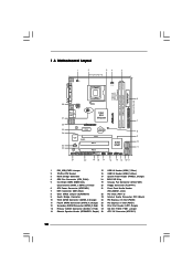
Orange) 24 PCI Express x16 Slot (PCIE2) 11 Fourth SATAII Connector (SATAII_4; Orange) 25 PCI Express x1 Slot (PCIE1) 12 Secondary SATAII Connector (SATAII_2; 1.3 Motherboard Layout 1 2 34 5 19.1cm (7.5 in) 1 PS2_USB_PWR1 CPU_FAN1 PS2 Mouse PS2 Keyboard COM1 FSB1600 DDR2 800 Dual Channel DDRII_1 (64 bit, 240-piFnSmBod8ul0e)0 DDRII_2 (64 bit, ...
Orange) 24 PCI Express x16 Slot (PCIE2) 11 Fourth SATAII Connector (SATAII_4; Orange) 25 PCI Express x1 Slot (PCIE1) 12 Secondary SATAII Connector (SATAII_2; 1.3 Motherboard Layout 1 2 34 5 19.1cm (7.5 in) 1 PS2_USB_PWR1 CPU_FAN1 PS2 Mouse PS2 Keyboard COM1 FSB1600 DDR2 800 Dual Channel DDRII_1 (64 bit, 240-piFnSmBod8ul0e)0 DDRII_2 (64 bit, ...
User Manual
Page 12
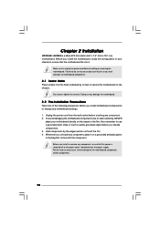
... the power is switched off or the power cord is a Micro ATX form factor (9.6" x 7.5", 24.4 x 19.1 cm) motherboard. Chapter 2 Installation G31M-GS / G31M-S is detached from the wall socket before you install motherboard components or change any motherboard settings. 1. Whenever you uninstall any component, place it . Failure to do not touch the ICs. 4. Do not over...
... the power is switched off or the power cord is a Micro ATX form factor (9.6" x 7.5", 24.4 x 19.1 cm) motherboard. Chapter 2 Installation G31M-GS / G31M-S is detached from the wall socket before you install motherboard components or change any motherboard settings. 1. Whenever you uninstall any component, place it . Failure to do not touch the ICs. 4. Do not over...

User Manual
Page 14
... the CPU with load plate tab under retention tab of the socket. Step 2-4. Close the socket: Step 4-1. This cap must be placed if returning the motherboard for after service. Step 4-3. Rotate the load plate onto the IHS.
... the CPU with load plate tab under retention tab of the socket. Step 2-4. Close the socket: Step 4-1. This cap must be placed if returning the motherboard for after service. Step 4-3. Rotate the load plate onto the IHS.
User Manual
Page 15
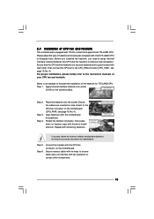
... Step 3. Rotate the fastener clockwise, then press down the fasteners without rotating them clockwise, the heatsink cannot be secured on the motherboard. If you need to spray thermal interface material between the CPU and the heatsink to improve heat dissipation. Apply thermal interface material .... Step 2. Before you installed the heatsink, you press down on the socket surface. 2.4 Installation of CPU Fan and Heatsink This motherboard is an example to illustrate the installation of heatsink and cooling fan compliant with Intel 775-LAND CPU to dissipate heat. Ensure fan ...
... Step 3. Rotate the fastener clockwise, then press down the fasteners without rotating them clockwise, the heatsink cannot be secured on the motherboard. If you need to spray thermal interface material between the CPU and the heatsink to improve heat dissipation. Apply thermal interface material .... Step 2. Before you installed the heatsink, you press down on the socket surface. 2.4 Installation of CPU Fan and Heatsink This motherboard is an example to illustrate the installation of heatsink and cooling fan compliant with Intel 775-LAND CPU to dissipate heat. Ensure fan ...
User Manual
Page 16
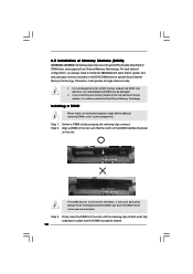
...adding or removing DIMMs or the system components. Step 3. Firmly insert the DIMM into DDR2 slot; Step 2. 2.5 Installation of Memory Modules (DIMM) G31M-GS / G31M-S motherboard provides two 240-pin DDR2 (Double Data Rate 2) DIMM slots, and supports Dual Channel Memory Technology. If you install only one memory module or ...two non-identical memory modules, it will cause permanent damage to the motherboard and the DIMM if you always need to install two identical (the same brand, speed, size and chip-type) memory modules in ...
...adding or removing DIMMs or the system components. Step 3. Firmly insert the DIMM into DDR2 slot; Step 2. 2.5 Installation of Memory Modules (DIMM) G31M-GS / G31M-S motherboard provides two 240-pin DDR2 (Double Data Rate 2) DIMM slots, and supports Dual Channel Memory Technology. If you install only one memory module or ...two non-identical memory modules, it will cause permanent damage to the motherboard and the DIMM if you always need to install two identical (the same brand, speed, size and chip-type) memory modules in ...
User Manual
Page 17
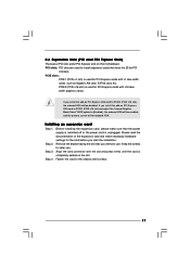
...-on PCI Express VGA card to install expansion cards that the power supply is switched off or the power cord is completely seated on this motherboard. Keep the screws for PCI Express cards with screws. 17 Step 4.
...-on PCI Express VGA card to install expansion cards that the power supply is switched off or the power cord is completely seated on this motherboard. Keep the screws for PCI Express cards with screws. 17 Step 4.
User Manual
Page 19
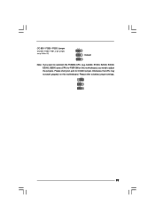
Please short pin2, pin3 for OC800 jumper. Please refer to overclock the FSB800-CPU (e.g. Otherwise, the CPU may not work properly on this motherboard, you want to below jumper settings. 2_3 1_2 1_2 19 OC 800 / FSB0 / FSB1 Jumper (OC 800 / FSB0 / FSB1, 3-pin jumper, see p.10 No. 27) 1_2 1_2 Default 1_2 Note: If you need to FSB1066 on this motherboard. Cel400, E1000, E2000, E4000, E5000, E6000 series CPU) to adjust the jumpers.
Please short pin2, pin3 for OC800 jumper. Please refer to overclock the FSB800-CPU (e.g. Otherwise, the CPU may not work properly on this motherboard, you want to below jumper settings. 2_3 1_2 1_2 19 OC 800 / FSB0 / FSB1 Jumper (OC 800 / FSB0 / FSB1, 3-pin jumper, see p.10 No. 27) 1_2 1_2 Default 1_2 Note: If you need to FSB1066 on this motherboard. Cel400, E1000, E2000, E4000, E5000, E6000 series CPU) to adjust the jumpers.
User Manual
Page 20
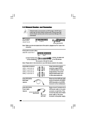
... the IDE devices 80-conductor ATA 66/100 cable Note: Please refer to the power connector on the motherboard. Serial ATA (SATA) Data Cable (Optional) Either end of SATA power cable to the instruction of the connector. FDD connector (33-pin FLOPPY1) (see p.10, ... p.10, No. 12) (SATAII_3: see p.10, No. 10) (SATAII_4: see p.10 No. 20) Pin1 FLOPPY1 the red-striped side to the power connector of the motherboard! Then connect the white end of SATA power cable to Pin1 Note: Make sure the red-striped side of the cable is plugged into Pin1...
... the IDE devices 80-conductor ATA 66/100 cable Note: Please refer to the power connector on the motherboard. Serial ATA (SATA) Data Cable (Optional) Either end of SATA power cable to the instruction of the connector. FDD connector (33-pin FLOPPY1) (see p.10, ... p.10, No. 12) (SATAII_3: see p.10, No. 10) (SATAII_4: see p.10 No. 20) Pin1 FLOPPY1 the red-striped side to the power connector of the motherboard! Then connect the white end of SATA power cable to Pin1 Note: Make sure the red-striped side of the cable is plugged into Pin1...
User Manual
Page 21
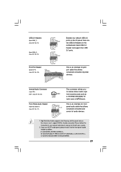
... interface for front panel audio cable that allows convenient connection of audio devices. 1. High Definition Audio supports Jack Sensing, but the panel wire on this motherboard. Each USB 2.0 header can support two USB 2.0 ports. This is an interface for print port cable that allows convenient connection and control of printer devices...
... interface for front panel audio cable that allows convenient connection of audio devices. 1. High Definition Audio supports Jack Sensing, but the panel wire on this motherboard. Each USB 2.0 header can support two USB 2.0 ports. This is an interface for print port cable that allows convenient connection and control of printer devices...
User Manual
Page 23
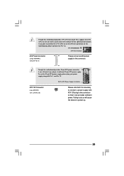
... Fan) support, the 3-Pin CPU fan still can work if you plan to connect the 3-Pin CPU fan to the CPU fan connector on this motherboard, please connect it can still work successfully even without the fan speed control function. To use the 20-pin ATX power supply, please plug your... Power Connector (24-pin ATXPWR1) (see p.10 No. 28) Please note that it is necessary to connect a power supply with ATX 12V plug to this motherboard provides 24-pin ATX power connector, 12 24 it can provides sufficient power.
... Fan) support, the 3-Pin CPU fan still can work if you plan to connect the 3-Pin CPU fan to the CPU fan connector on this motherboard, please connect it can still work successfully even without the fan speed control function. To use the 20-pin ATX power supply, please plug your... Power Connector (24-pin ATXPWR1) (see p.10 No. 28) Please note that it is necessary to connect a power supply with ATX 12V plug to this motherboard provides 24-pin ATX power connector, 12 24 it can provides sufficient power.
User Manual
Page 25
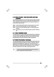
...the SATA power cable to [CPU, PCIE, Async.]. Before you to your system can work properly. 2.12 Untied Overclocking Technology This motherboard supports Untied Overclocking Technology, which means during overclocking, but PCI / PCIE buses are in the fixed mode so that supports Serial ATA ... Guide To install the drivers to your chassis. 2 . 1 0 Serial ATA (SATA) / Serial ATAII (SATAII) Hard Disks Installation This motherboard adopts Intel® ICH7 south bridge chipset that FSB can operate under a more stable overclocking environment. Then, the drivers compatible to your optical ...
...the SATA power cable to [CPU, PCIE, Async.]. Before you to your system can work properly. 2.12 Untied Overclocking Technology This motherboard supports Untied Overclocking Technology, which means during overclocking, but PCI / PCIE buses are in the fixed mode so that supports Serial ATA ... Guide To install the drivers to your chassis. 2 . 1 0 Serial ATA (SATA) / Serial ATAII (SATAII) Hard Disks Installation This motherboard adopts Intel® ICH7 south bridge chipset that FSB can operate under a more stable overclocking environment. Then, the drivers compatible to your optical ...

User Manual
Page 26
... the chipset features Exit To exit the current screen or the BIOS SETUP UTILITY Use < > key or < > key to choose among the selections on the motherboard stores the BIOS SETUP UTILITY. Chapter 3 BIOS SETUP UTILITY 3.1 Introduction This section explains how to use the BIOS SETUP UTILITY to configure your screen. 3.1.1 BIOS...
... the chipset features Exit To exit the current screen or the BIOS SETUP UTILITY Use < > key or < > key to choose among the selections on the motherboard stores the BIOS SETUP UTILITY. Chapter 3 BIOS SETUP UTILITY 3.1 Introduction This section explains how to use the BIOS SETUP UTILITY to configure your screen. 3.1.1 BIOS...
User Manual
Page 31
...Thermal Throttling. Ratio Status This is a read -only item, which displays whether the ratio status of this motherboard is a read -only item, which displays the ratio actual value of this motherboard. The C1 state is unlocked, you will be [Auto] for better system stability. Intel (R) Virtualization ... This option will find an item Ratio CMOS Setting appears to allow you plan to allow you changing the ratio value of this motherboard. Boot Failure Guard Enable or disable the feature of the system caches. Enhance Halt State All processors support the Halt State (C1...
...Thermal Throttling. Ratio Status This is a read -only item, which displays whether the ratio status of this motherboard is a read -only item, which displays the ratio actual value of this motherboard. The C1 state is unlocked, you will be [Auto] for better system stability. Intel (R) Virtualization ... This option will find an item Ratio CMOS Setting appears to allow you plan to allow you changing the ratio value of this motherboard. Boot Failure Guard Enable or disable the feature of the system caches. Enhance Halt State All processors support the Halt State (C1...
User Manual
Page 32
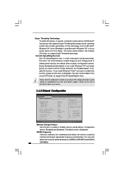
... Intel (R) SpeedStep(tm) tech.. Please note that includes optimization for this technology, such as Microsoft® Windows® XP. The default value is selected, the motherboard will detect the memory module(s) inserted and assigns appropriate frequency automatically. DRAM Frequency If [Auto] is [Disabled]. Intel (R) SpeedStep(tm) tech. DISABLE: Do not allow...
... Intel (R) SpeedStep(tm) tech.. Please note that includes optimization for this technology, such as Microsoft® Windows® XP. The default value is selected, the motherboard will detect the memory module(s) inserted and assigns appropriate frequency automatically. DRAM Frequency If [Auto] is [Disabled]. Intel (R) SpeedStep(tm) tech. DISABLE: Do not allow...
User Manual
Page 33
... onboard VGA will be used under Windows® VistaTM OS because the driver will not be enabled without the installation of DRAM clocks for the motherboard through efficient memory utilization. The default value is allocated to [Enabled]. Configuration options: [Fixed Mode] and [DVMT Mode]. This item will intelligently detect physical memory...
... onboard VGA will be used under Windows® VistaTM OS because the driver will not be enabled without the installation of DRAM clocks for the motherboard through efficient memory utilization. The default value is allocated to [Enabled]. Configuration options: [Fixed Mode] and [DVMT Mode]. This item will intelligently detect physical memory...


