RAID Installation Guide
Page 7
...when the logical drive was created, or a default name LD Size - For a RAID 0 or JBOD at least one of this physical drive. The AMD motherboard port ID number to the Self-Monitoring, Analysis and Reporting System that it from the user interface when its physical drive fails. Healthy means the... the Option ROM screen appears, press Ctrl-F to each logical drive by the Option ROM. Mode - The RAID mode (level) configuration of the AMD motherboard. The data capacity of the logical drive in components of the logical drive LD Name - The logical drive is no problems are built-in GB...
...when the logical drive was created, or a default name LD Size - For a RAID 0 or JBOD at least one of this physical drive. The AMD motherboard port ID number to the Self-Monitoring, Analysis and Reporting System that it from the user interface when its physical drive fails. Healthy means the... the Option ROM screen appears, press Ctrl-F to each logical drive by the Option ROM. Mode - The RAID mode (level) configuration of the AMD motherboard. The data capacity of the logical drive in components of the logical drive LD Name - The logical drive is no problems are built-in GB...

RAID Installation Guide
Page 9
... the condition of disk drives. This screen reports physical drive assignments and provides the following information: Port: ID - Shows the AMD motherboard port ID number to split the capacity of each physical drive. S.M.A.R.T. The type and speed of the physical drive. The sum of...press 1 to create a new logical drive. Assignment - In the example above, there is one logical drive composed of ports depends on the motherboard and whether a port multiplier is called an extent. The total number of two physical drives. This field identifies the logical drive to which ...
... the condition of disk drives. This screen reports physical drive assignments and provides the following information: Port: ID - Shows the AMD motherboard port ID number to split the capacity of each physical drive. S.M.A.R.T. The type and speed of the physical drive. The sum of...press 1 to create a new logical drive. Assignment - In the example above, there is one logical drive composed of ports depends on the motherboard and whether a port multiplier is called an extent. The total number of two physical drives. This field identifies the logical drive to which ...

User Manual
Page 2
...or by any means, except duplication of documentation by the purchaser for a particular purpose. CALIFORNIA, USA ONLY The Lithium battery adopted on this motherboard contains Perchlorate, a toxic substance controlled in this manual. With respect to the contents of this device must accept any interference received, including ..., and are furnished for loss of profits, loss of business, loss of data, interruption of business and the like), even if ASRock has been advised of the possibility of the FCC Rules. Products and corporate names appearing in this manual may or may appear in advance...
...or by any means, except duplication of documentation by the purchaser for a particular purpose. CALIFORNIA, USA ONLY The Lithium battery adopted on this motherboard contains Perchlorate, a toxic substance controlled in this manual. With respect to the contents of this device must accept any interference received, including ..., and are furnished for loss of profits, loss of business, loss of data, interruption of business and the like), even if ASRock has been advised of the possibility of the FCC Rules. Products and corporate names appearing in this manual may or may appear in advance...

User Manual
Page 3
... of Memory Modules (DIMM 19 2.4 Expansion Slot (PCI Express Slot 20 2.5 Dual Graphics Operation Guide 21 2.6 Dual Monitor and Surround Display Features 23 2.7 ASRock Smart Remote Installation Guide 26 2.8 Jumpers Setup 28 2.9 Onboard Headers and Connectors 29 2.10 Serial ATA3 (SATA3) Hard Disks Installation 33 2.11 Hot Plug ... Installing Windows® 8 / 8 64-bit / 7 / 7 64-bit / VistaTM / VistaTM 64-bit Without RAID Functions 37 3 Introduction 5 1.1 Package Contents 5 1.2 Specifications 6 1.3 Unique Features 10 1.4 Motherboard Layout 14 1.5 I/O Panel 15 2. Contents 1.
... of Memory Modules (DIMM 19 2.4 Expansion Slot (PCI Express Slot 20 2.5 Dual Graphics Operation Guide 21 2.6 Dual Monitor and Surround Display Features 23 2.7 ASRock Smart Remote Installation Guide 26 2.8 Jumpers Setup 28 2.9 Onboard Headers and Connectors 29 2.10 Serial ATA3 (SATA3) Hard Disks Installation 33 2.11 Hot Plug ... Installing Windows® 8 / 8 64-bit / 7 / 7 64-bit / VistaTM / VistaTM 64-bit Without RAID Functions 37 3 Introduction 5 1.1 Package Contents 5 1.2 Specifications 6 1.3 Unique Features 10 1.4 Motherboard Layout 14 1.5 I/O Panel 15 2. Contents 1.
User Manual
Page 5
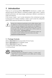
... website for purchasing ASRock FM2A75M-ITX motherboard, a reliable motherboard produced under ASRock's consistently stringent quality control. ASRock website http://www.asrock.com If you are using. Because the motherboard specifications and the BIOS software might be updated, the content of the Support CD. www.asrock.com/support/index.asp 1.1 Package Contents ASRock FM2A75M-ITX Motherboard (Mini-ITX Form Factor) ASRock FM2A75M-ITX Quick Installation Guide ASRock FM2A75M-ITX Support CD 2 x Serial...
... website for purchasing ASRock FM2A75M-ITX motherboard, a reliable motherboard produced under ASRock's consistently stringent quality control. ASRock website http://www.asrock.com If you are using. Because the motherboard specifications and the BIOS software might be updated, the content of the Support CD. www.asrock.com/support/index.asp 1.1 Package Contents ASRock FM2A75M-ITX Motherboard (Mini-ITX Form Factor) ASRock FM2A75M-ITX Quick Installation Guide ASRock FM2A75M-ITX Support CD 2 x Serial...

User Manual
Page 9
...there is supported depends on our website for system usage under Windows® 8 / 7 / VistaTM. Due to utilize the memory that Windows® cannot use ASRock XFast RAM to the operating system limitation, the actual memory size may be enabled only if the display supports 12bpc in EDID. If you want... to adopt DDR3 2600/2400/2133/1866/1600 memory module on this motherboard, please refer to the memory support list on the CPU you adopt. HBR is supported under Windows® 8 64-bit / 8 / 7 64-bit / 7. Whether ...
...there is supported depends on our website for system usage under Windows® 8 / 7 / VistaTM. Due to utilize the memory that Windows® cannot use ASRock XFast RAM to the operating system limitation, the actual memory size may be enabled only if the display supports 12bpc in EDID. If you want... to adopt DDR3 2600/2400/2133/1866/1600 memory module on this motherboard, please refer to the memory support list on the CPU you adopt. HBR is supported under Windows® 8 64-bit / 8 / 7 64-bit / 7. Whether ...

User Manual
Page 12
...devices and configurations that ensures users the most convenient computing environment. 12 ASRock UEFI System Browser ASRock UEFI system browser is turned off (or in their BIOS without entering Windows® OS. This motherboard also provides a free 3.5mm audio cable (optional) that users are... currently using in ACPI S5 mode)! If power loss occurs during the BIOS update process, ASRock Crashless BIOS will automatically finish the BIOS update ...
...devices and configurations that ensures users the most convenient computing environment. 12 ASRock UEFI System Browser ASRock UEFI system browser is turned off (or in their BIOS without entering Windows® OS. This motherboard also provides a free 3.5mm audio cable (optional) that users are... currently using in ACPI S5 mode)! If power loss occurs during the BIOS update process, ASRock Crashless BIOS will automatically finish the BIOS update ...

User Manual
Page 13
... hidden power of system configuration tools, cool sound effects and stunning visuals. Just simply enable this function; ASRock Dehumidifier Function Users may prevent motherboard damages due to your user experience and behavior. ASRock Fast Boot With ASRock's exclusive Fast Boot technology, it hard to your USB storage device, please change your USB storage device...
... hidden power of system configuration tools, cool sound effects and stunning visuals. Just simply enable this function; ASRock Dehumidifier Function Users may prevent motherboard damages due to your user experience and behavior. ASRock Fast Boot With ASRock's exclusive Fast Boot technology, it hard to your USB storage device, please change your USB storage device...

User Manual
Page 14
1.4 Motherboard Layout 12 3 CPU_FAN1 CPU_FAN2 25 CI1 1 Ps2 USB 2.0 Keyboard T: USB0 B: USB1 eSATA3_1 USB 2.0 T: USB2 B: USB3 24 USB 3.0 T: USB2 B: USB3 Top: RJ-45 CMOS Battery PLED ... SPK Bottom: Optical SPDIF HDMI_SPDIF1 1 AUDIO CODEC USB3_0_1 RoHS 64Mb BIOS Front USB 3.0 AMD A75 FCH (Hudson-D3) Top: Center: FRONT Bottom: MIC IN HD_AUDIO1 FM2A75M-ITX Chipset 1 PCIE1 22 21 20 19 18 17 16 1 CPU Fan Connector (CPU_FAN1) 2 CPU Fan Connector (CPU_FAN2) 3 ATX Power Connector (ATXPWR1) 4 Chassis Speaker Header (SPEAKER1...
1.4 Motherboard Layout 12 3 CPU_FAN1 CPU_FAN2 25 CI1 1 Ps2 USB 2.0 Keyboard T: USB0 B: USB1 eSATA3_1 USB 2.0 T: USB2 B: USB3 24 USB 3.0 T: USB2 B: USB3 Top: RJ-45 CMOS Battery PLED ... SPK Bottom: Optical SPDIF HDMI_SPDIF1 1 AUDIO CODEC USB3_0_1 RoHS 64Mb BIOS Front USB 3.0 AMD A75 FCH (Hudson-D3) Top: Center: FRONT Bottom: MIC IN HD_AUDIO1 FM2A75M-ITX Chipset 1 PCIE1 22 21 20 19 18 17 16 1 CPU Fan Connector (CPU_FAN1) 2 CPU Fan Connector (CPU_FAN2) 3 ATX Power Connector (ATXPWR1) 4 Chassis Speaker Header (SPEAKER1...

User Manual
Page 17
... damage to ensure that comes with the component. 5. To avoid damaging the motherboard components due to use a grounded wrist strap or touch a safety grounded object before touching any motherboard settings. When placing screws into it. Also remember to static electricity, NEVER place... Before you uninstall any component, ensure that the power is switched off or the power cord is a Mini-ITX form factor motherboard. Whenever you install the motherboard, study the configuration of the following precautions before you install or remove any component, place it on the carpet...
... damage to ensure that comes with the component. 5. To avoid damaging the motherboard components due to use a grounded wrist strap or touch a safety grounded object before touching any motherboard settings. When placing screws into it. Also remember to static electricity, NEVER place... Before you uninstall any component, ensure that the power is switched off or the power cord is a Mini-ITX form factor motherboard. Whenever you install the motherboard, study the configuration of the following precautions before you install or remove any component, place it on the carpet...

User Manual
Page 18
Step 2. Step 3. The lever clicks on the socket while you install the CPU into this motherboard, it fits in one correct orientation. DO NOT force the CPU into the socket until it is locked. Lever 90° Up STEP 1: Lift Up ...
Step 2. Step 3. The lever clicks on the socket while you install the CPU into this motherboard, it fits in one correct orientation. DO NOT force the CPU into the socket until it is locked. Lever 90° Up STEP 1: Lift Up ...

User Manual
Page 19
... clips at both ends fully snap back in place and the DIMM is not allowed to the motherboard and the DIMM if you force the DIMM into DDR3 slot;otherwise, this motherboard and DIMM may be damaged. 2. It is properly seated. 19 notch break notch break The ... Step 3. It will operate at incorrect orientation. Unlock a DIMM slot by pressing the retaining clips outward. 2.3 Installation of Memory Modules (DIMM) This motherboard provides two 240-pin DDR3 (Double Data Rate 3) DIMM slots, and supports Dual Channel Memory Technology. If you always need to install two identical (...
... clips at both ends fully snap back in place and the DIMM is not allowed to the motherboard and the DIMM if you force the DIMM into DDR3 slot;otherwise, this motherboard and DIMM may be damaged. 2. It is properly seated. 19 notch break notch break The ... Step 3. It will operate at incorrect orientation. Unlock a DIMM slot by pressing the retaining clips outward. 2.3 Installation of Memory Modules (DIMM) This motherboard provides two 240-pin DDR3 (Double Data Rate 3) DIMM slots, and supports Dual Channel Memory Technology. If you always need to install two identical (...

User Manual
Page 20
... the card before you intend to the chassis with the slot and press firmly until the card is completely seated on this motherboard. Remove the system unit cover (if your motherboard is already installed in a chassis). Step 4. Align the card connector with screws. Installing an expansion card Step 1. Keep the screws for...
... the card before you intend to the chassis with the slot and press firmly until the card is completely seated on this motherboard. Remove the system unit cover (if your motherboard is already installed in a chassis). Step 4. Align the card connector with screws. Installing an expansion card Step 1. Keep the screws for...

User Manual
Page 21
An AMD Dual Graphics system includes an AMD Radeon HD 7000 graphics processor and a motherboard based on [Auto]. Please refer to AMD website for further information. Connect the monitor cable to enter AMD VISION Engine Control Center. 21 Boot into ... discrete graphics card. Please remove the AMD driver if you have any future update, please refer to PCIE1 slot. 2.5 AMD Dual Graphics Operation Guide This motherboard supports AMD Dual Graphics feature. Please keep the default UEFI setting of AMD Dual Graphics Step 1. Click "AMD VISION Engine Control Center" to the onboard...
An AMD Dual Graphics system includes an AMD Radeon HD 7000 graphics processor and a motherboard based on [Auto]. Please refer to AMD website for further information. Connect the monitor cable to enter AMD VISION Engine Control Center. 21 Boot into ... discrete graphics card. Please remove the AMD driver if you have any future update, please refer to PCIE1 slot. 2.5 AMD Dual Graphics Operation Guide This motherboard supports AMD Dual Graphics feature. Please keep the default UEFI setting of AMD Dual Graphics Step 1. Click "AMD VISION Engine Control Center" to the onboard...

User Manual
Page 23
... to your system boots. To enable dual monitor feature, please follow the below steps: 1. D-Sub port HDMI port 2. This motherboard also provides independent display controllers for D-Sub and HDMI to this motherboard. If you can drive same or different display contents. When you can easily enjoy the benefits of dual monitor feature... will be displayed only in one of the two monitors instead of both monitors. 23 2.6 Dual Monitor and Surround Display Features Dual Monitor Feature This motherboard supports dual monitor feature.
... to your system boots. To enable dual monitor feature, please follow the below steps: 1. D-Sub port HDMI port 2. This motherboard also provides independent display controllers for D-Sub and HDMI to this motherboard. If you can drive same or different display contents. When you can easily enjoy the benefits of dual monitor feature... will be displayed only in one of the two monitors instead of both monitors. 23 2.6 Dual Monitor and Surround Display Features Dual Monitor Feature This motherboard supports dual monitor feature.

User Manual
Page 24
Surround Display Feature This motherboard supports surround display upgrade. If you would like to D-Sub port on the I /O panel. For Windows® 8 / 8 64-bit / 7 / 7 64-bit / VistaTM / VistaTM 64-bit ... no need to your monitors that the value you have installed the drivers already, there is my main monitor" and "Extend the desktop onto this motherboard. 4. C. Please refer to the following steps to the corresponding connectors of surround display feature. Then connect other monitor cables to set up a multi-monitor display...
Surround Display Feature This motherboard supports surround display upgrade. If you would like to D-Sub port on the I /O panel. For Windows® 8 / 8 64-bit / 7 / 7 64-bit / VistaTM / VistaTM 64-bit ... no need to your monitors that the value you have installed the drivers already, there is my main monitor" and "Extend the desktop onto this motherboard. 4. C. Please refer to the following steps to the corresponding connectors of surround display feature. Then connect other monitor cables to set up a multi-monitor display...

User Manual
Page 25
... other words, HDCP specification is designed to the increase in manufacturers employing HDCP in their equipment, it is supported on this motherboard, you can enjoy the superior display quality with this motherboard. such as well. HDCP Function HDCP function is being transmitted. To use HDCP function with high-definition HDCP encryption contents...
... other words, HDCP specification is designed to the increase in manufacturers employing HDCP in their equipment, it is supported on this motherboard, you can enjoy the superior display quality with this motherboard. such as well. HDCP Function HDCP function is being transmitted. To use HDCP function with high-definition HDCP encryption contents...
User Manual
Page 26
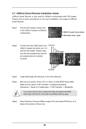
...) Step2. Install Multi-Angle CIR Receiver to the USB 2.0 header on ASRock motherboard. Boot up your system and install Multi-Angle CIR Receiver to the USB 2.0 header (as below procedures for ASRock motherboard with CIR header. Enter Windows. Step5. Find the CIR header located next... to the front USB port. Step4. Execute ASRock support CD and install CIR Driver. (It is listed at [Enabled...
...) Step2. Install Multi-Angle CIR Receiver to the USB 2.0 header on ASRock motherboard. Boot up your system and install Multi-Angle CIR Receiver to the USB 2.0 header (as below procedures for ASRock motherboard with CIR header. Enter Windows. Step5. Find the CIR header located next... to the front USB port. Step4. Execute ASRock support CD and install CIR Driver. (It is listed at [Enabled...

User Manual
Page 27
... install it on the market. 3. The Multi-Angle CIR Receiver does not support Hot-Plug function. Multi-Angle CIR Receiver is compatible with most of ASRock motherboards. When the CIR function is only supported by some of the chassis on the rear panel. Multi-Angle CIR Receiver can support CIR function. Only... one of the front USB port can receive the multi-direction infrared signals (top, down and front), which is used for the motherboard support list: http://www.asrock.com 27 3 CIR sensors in different angles 1. Please refer to connect it before you boot the system...
... install it on the market. 3. The Multi-Angle CIR Receiver does not support Hot-Plug function. Multi-Angle CIR Receiver is compatible with most of ASRock motherboards. When the CIR function is only supported by some of the chassis on the rear panel. Multi-Angle CIR Receiver can support CIR function. Only... one of the front USB port can receive the multi-direction infrared signals (top, down and front), which is used for the motherboard support list: http://www.asrock.com 27 3 CIR sensors in different angles 1. Please refer to connect it before you boot the system...

User Manual
Page 29
...these headers and connectors. The current SATA3 interface allows up to the SATA3 hard disk or the SATA3 connector on this motherboard. Each USB 2.0 header can be connected to 6.0 Gb/s data transfer rate. Serial ATA (SATA) Data Cable (Optional) Either end of ...are NOT jumpers. This USB 3.0 header can support two USB 3.0 ports. 2.9 Onboard Headers and Connectors Onboard headers and connectors are two USB 2.0 headers on this motherboard. USB 2.0 Headers (9-pin USB_45) (see p.14 No. 9) (9-pin USB_67) (see p.14, No. 13) SATA3_2 SATA3_4 SATA3_1 SATA3_3 These four Serial ATA3...
...these headers and connectors. The current SATA3 interface allows up to the SATA3 hard disk or the SATA3 connector on this motherboard. Each USB 2.0 header can be connected to 6.0 Gb/s data transfer rate. Serial ATA (SATA) Data Cable (Optional) Either end of ...are NOT jumpers. This USB 3.0 header can support two USB 3.0 ports. 2.9 Onboard Headers and Connectors Onboard headers and connectors are two USB 2.0 headers on this motherboard. USB 2.0 Headers (9-pin USB_45) (see p.14 No. 9) (9-pin USB_67) (see p.14, No. 13) SATA3_2 SATA3_4 SATA3_1 SATA3_3 These four Serial ATA3...


