RAID Installation Guide
Page 7
... logical drive is still operational, meaning you cannot read and write data to it. For a RAID 0 or JBOD at least one of the AMD motherboard. refers to it finds. Status - For RAID levels 1, 5, and 10, the logical drive contains a failed physical drive. S.M.A.R.T. When the Option...attached. Critical - Device Name - Then you assigned when the logical drive was created, or a default name LD Size - The AMD motherboard port ID number to it displays pertinent information about the RAID logical drives that monitors the condition of the logical drive in the logical ...
... logical drive is still operational, meaning you cannot read and write data to it. For a RAID 0 or JBOD at least one of the AMD motherboard. refers to it finds. Status - For RAID levels 1, 5, and 10, the logical drive contains a failed physical drive. S.M.A.R.T. When the Option...attached. Critical - Device Name - Then you assigned when the logical drive was created, or a default name LD Size - The AMD motherboard port ID number to it displays pertinent information about the RAID logical drives that monitors the condition of the logical drive in the logical ...

RAID Installation Guide
Page 9
..., and model number (if applicable) of disk drives. This field identifies the logical drive to split the capacity of ports depends on the motherboard and whether a port multiplier is attached. The Option ROM Utility allows you to which a particular physical drive is connected. 1.6 Viewing Drive ...- Healthy means the disk drive is a portion of the physical drive, such as SATA 1.5 Gb/s, 3.0 Gb/s, or 6.0 Gb/s. Shows the AMD motherboard port ID number to be used in GB (gigabytes) of the physical drive. 9 Reflects the capacity in a logical drive is slightly smaller than the...
..., and model number (if applicable) of disk drives. This field identifies the logical drive to split the capacity of ports depends on the motherboard and whether a port multiplier is attached. The Option ROM Utility allows you to which a particular physical drive is connected. 1.6 Viewing Drive ...- Healthy means the disk drive is a portion of the physical drive, such as SATA 1.5 Gb/s, 3.0 Gb/s, or 6.0 Gb/s. Shows the AMD motherboard port ID number to be used in GB (gigabytes) of the physical drive. 9 Reflects the capacity in a logical drive is slightly smaller than the...

User Manual
Page 2
... ASRock, its directors, officers, employees, or agents be registered trademarks or copyrights of the FCC Rules. "Perchlorate Material-special handling may not be liable for any errors or omissions that may appear in this manual. Products and corporate names appearing in this motherboard ...contains Perchlorate, a toxic substance controlled in advance. CALIFORNIA, USA ONLY The Lithium battery adopted on this manual may or may apply, see www.dtsc.ca.gov/hazardouswaste/perchlorate" ASRock Website: http://www...
... ASRock, its directors, officers, employees, or agents be registered trademarks or copyrights of the FCC Rules. "Perchlorate Material-special handling may not be liable for any errors or omissions that may appear in this manual. Products and corporate names appearing in this motherboard ...contains Perchlorate, a toxic substance controlled in advance. CALIFORNIA, USA ONLY The Lithium battery adopted on this manual may or may apply, see www.dtsc.ca.gov/hazardouswaste/perchlorate" ASRock Website: http://www...

User Manual
Page 3
... Features 10 1.4 Motherboard Layout 14 1.5 I/O Panel 15 2. Contents 1. Installation 17 Pre-installation Precautions 17 2.1 CPU Installation 18 2.2 Installation of CPU Fan and Heatsink 18 2.3 Installation of Memory Modules (DIMM 19 2.4 Expansion Slot (PCI Express Slot 20 2.5 Dual Graphics Operation Guide 21 2.6 Dual Monitor and Surround Display Features 23 2.7 ASRock Smart Remote Installation...
... Features 10 1.4 Motherboard Layout 14 1.5 I/O Panel 15 2. Contents 1. Installation 17 Pre-installation Precautions 17 2.1 CPU Installation 18 2.2 Installation of CPU Fan and Heatsink 18 2.3 Installation of Memory Modules (DIMM 19 2.4 Expansion Slot (PCI Express Slot 20 2.5 Dual Graphics Operation Guide 21 2.6 Dual Monitor and Surround Display Features 23 2.7 ASRock Smart Remote Installation...
User Manual
Page 5
... are using. It delivers excellent performance with robust design conforming to ASRock's commitment to change without further notice. www.asrock.com/support/index.asp 1.1 Package Contents ASRock FM2A75M-ITX Motherboard (Mini-ITX Form Factor) ASRock FM2A75M-ITX Quick Installation Guide ASRock FM2A75M-ITX Support CD 2 x Serial ATA (SATA) Data Cables (Optional) 1 x I/O Panel Shield ASRock Reminds You... Introduction Thank you for specific information about the...
... are using. It delivers excellent performance with robust design conforming to ASRock's commitment to change without further notice. www.asrock.com/support/index.asp 1.1 Package Contents ASRock FM2A75M-ITX Motherboard (Mini-ITX Form Factor) ASRock FM2A75M-ITX Quick Installation Guide ASRock FM2A75M-ITX Support CD 2 x Serial ATA (SATA) Data Cables (Optional) 1 x I/O Panel Shield ASRock Reminds You... Introduction Thank you for specific information about the...

User Manual
Page 9
...64-bit / 7 / VistaTM 64-bit / VistaTM. 9 HBR is supported depends on our website for system usage under Windows® 8 / 7 / VistaTM. You can use . 3. ASRock website http://www.asrock.com 2. Deep Color mode will be less than 4GB for the reservation for the compatible memory modules. Due to utilize the memory that Windows...only if the display supports 12bpc in EDID. If you want to adopt DDR3 2600/2400/2133/1866/1600 memory module on this motherboard, please refer to the memory support list on the CPU you adopt. Whether 2600/2400/2133/1866/1600MHz memory speed is supported under...
...64-bit / 7 / VistaTM 64-bit / VistaTM. 9 HBR is supported depends on our website for system usage under Windows® 8 / 7 / VistaTM. You can use . 3. ASRock website http://www.asrock.com 2. Deep Color mode will be less than 4GB for the reservation for the compatible memory modules. Due to utilize the memory that Windows...only if the display supports 12bpc in EDID. If you want to adopt DDR3 2600/2400/2133/1866/1600 memory module on this motherboard, please refer to the memory support list on the CPU you adopt. Whether 2600/2400/2133/1866/1600MHz memory speed is supported under...

User Manual
Page 12
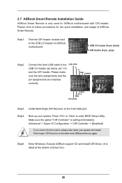
.... ASRock Internet Flash ASRock Internet Flash searches for available UEFI firmware updates from the portable audio devices, such like MP3 player or mobile phone to modify the system time are required. Please note that you can easily examine the current system configuration in their BIOS without permission to your USB disk. This motherboard...
.... ASRock Internet Flash ASRock Internet Flash searches for available UEFI firmware updates from the portable audio devices, such like MP3 player or mobile phone to modify the system time are required. Please note that you can easily examine the current system configuration in their BIOS without permission to your USB disk. This motherboard...

User Manual
Page 13
...174; 8 brings the ultimate boot up to UEFI technology is included in the very beginning. 13 Just simply enable this function; ASRock Dehumidifier Function Users may prevent motherboard damages due to "RAID", then you to copy the RAID driver from a cold boot. After copying the RAID driver to ...your USB storage device, please change your user experience and behavior. ASRock Restart to Windows® 8 from a support CD to unleash the ...
...174; 8 brings the ultimate boot up to UEFI technology is included in the very beginning. 13 Just simply enable this function; ASRock Dehumidifier Function Users may prevent motherboard damages due to "RAID", then you to copy the RAID driver from a cold boot. After copying the RAID driver to ...your USB storage device, please change your user experience and behavior. ASRock Restart to Windows® 8 from a support CD to unleash the ...

User Manual
Page 14
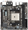
1.4 Motherboard Layout 12 3 CPU_FAN1 CPU_FAN2 25 CI1 1 Ps2 USB 2.0 Keyboard T: USB0 B: USB1 eSATA3_1 USB 2.0 T: USB2 B: USB3 24 USB 3.0 T: USB2 B: USB3 Top: RJ-45 CMOS Battery PLED ... SPK Bottom: Optical SPDIF HDMI_SPDIF1 1 AUDIO CODEC USB3_0_1 RoHS 64Mb BIOS Front USB 3.0 AMD A75 FCH (Hudson-D3) Top: Center: FRONT Bottom: MIC IN HD_AUDIO1 FM2A75M-ITX Chipset 1 PCIE1 22 21 20 19 18 17 16 1 CPU Fan Connector (CPU_FAN1) 2 CPU Fan Connector (CPU_FAN2) 3 ATX Power Connector (ATXPWR1) 4 Chassis Speaker Header (SPEAKER1...
1.4 Motherboard Layout 12 3 CPU_FAN1 CPU_FAN2 25 CI1 1 Ps2 USB 2.0 Keyboard T: USB0 B: USB1 eSATA3_1 USB 2.0 T: USB2 B: USB3 24 USB 3.0 T: USB2 B: USB3 Top: RJ-45 CMOS Battery PLED ... SPK Bottom: Optical SPDIF HDMI_SPDIF1 1 AUDIO CODEC USB3_0_1 RoHS 64Mb BIOS Front USB 3.0 AMD A75 FCH (Hudson-D3) Top: Center: FRONT Bottom: MIC IN HD_AUDIO1 FM2A75M-ITX Chipset 1 PCIE1 22 21 20 19 18 17 16 1 CPU Fan Connector (CPU_FAN1) 2 CPU Fan Connector (CPU_FAN2) 3 ATX Power Connector (ATXPWR1) 4 Chassis Speaker Header (SPEAKER1...

User Manual
Page 17
... that the power is switched off or the power cord is a Mini-ITX form factor motherboard. Failure to do not touch the ICs. 4. Hold components by the edges and do so may damage the motherboard. 17 Before you install or remove any component. 2. Doing so may cause... that comes with the component. 5. When placing screws into it on the carpet or the like. Whenever you install the motherboard, study the configuration of the following precautions before you install motherboard components or change any component, place it . Unplug the power cord from the power supply. 2.
... that the power is switched off or the power cord is a Mini-ITX form factor motherboard. Failure to do not touch the ICs. 4. Hold components by the edges and do so may damage the motherboard. 17 Before you install or remove any component. 2. Doing so may cause... that comes with the component. 5. When placing screws into it on the carpet or the like. Whenever you install the motherboard, study the configuration of the following precautions before you install motherboard components or change any component, place it . Unplug the power cord from the power supply. 2.

User Manual
Page 18
... pins. The lever clicks on the side tab to avoid bending of the CPU fan and the heatsink. 18 Carefully insert the CPU into this motherboard, it fits in good contact with a small triangle. Unlock the socket by lifting the lever up to dissipate heat. DO NOT force the CPU into...
... pins. The lever clicks on the side tab to avoid bending of the CPU fan and the heatsink. 18 Carefully insert the CPU into this motherboard, it fits in good contact with a small triangle. Unlock the socket by lifting the lever up to dissipate heat. DO NOT force the CPU into...

User Manual
Page 19
...1. Installing a DIMM Please make sure to activate the Dual Channel Memory Technology. Step 2. Otherwise, it will cause permanent damage to the motherboard and the DIMM if you install only one correct orientation. It is unable to disconnect power supply before adding or removing DIMMs or the... DIMM on the slot such that the notch on the DIMM matches the break on the slot. 2.3 Installation of Memory Modules (DIMM) This motherboard provides two 240-pin DDR3 (Double Data Rate 3) DIMM slots, and supports Dual Channel Memory Technology. Step 3. Firmly insert the DIMM into ...
...1. Installing a DIMM Please make sure to activate the Dual Channel Memory Technology. Step 2. Otherwise, it will cause permanent damage to the motherboard and the DIMM if you install only one correct orientation. It is unable to disconnect power supply before adding or removing DIMMs or the... DIMM on the slot such that the notch on the DIMM matches the break on the slot. 2.3 Installation of Memory Modules (DIMM) This motherboard provides two 240-pin DDR3 (Double Data Rate 3) DIMM slots, and supports Dual Channel Memory Technology. Step 3. Firmly insert the DIMM into ...

User Manual
Page 20
.... Before installing the expansion card, please make necessary hardware settings for PCI Express x16 lane width graphics cards. Remove the system unit cover (if your motherboard is used for the card before you intend to the chassis with the slot and press firmly until the card is completely seated on this...
.... Before installing the expansion card, please make necessary hardware settings for PCI Express x16 lane width graphics cards. Remove the system unit cover (if your motherboard is used for the card before you intend to the chassis with the slot and press firmly until the card is completely seated on this...

User Manual
Page 21
...setting of AMD Dual Graphics Step 1. Step 3. An AMD Dual Graphics system includes an AMD Radeon HD 7000 graphics processor and a motherboard based on [Auto]. Please refer to the onboard VGA port. Step 2. Step 5. Step 6. Right-click the desktop. Currently, AMD Dual...AMD VISION Engine Control Center" to PCIE1 slot. Install the onboard VGA driver from onboard display only. 2.5 AMD Dual Graphics Operation Guide This motherboard supports AMD Dual Graphics feature. Enjoy the benefit of "Dual Graphics" option on an AMD A75 FCH (Hudson-D3) integrated chipset, all ...
...setting of AMD Dual Graphics Step 1. Step 3. An AMD Dual Graphics system includes an AMD Radeon HD 7000 graphics processor and a motherboard based on [Auto]. Please refer to the onboard VGA port. Step 2. Step 5. Step 6. Right-click the desktop. Currently, AMD Dual...AMD VISION Engine Control Center" to PCIE1 slot. Install the onboard VGA driver from onboard display only. 2.5 AMD Dual Graphics Operation Guide This motherboard supports AMD Dual Graphics feature. Enjoy the benefit of "Dual Graphics" option on an AMD A75 FCH (Hudson-D3) integrated chipset, all ...

User Manual
Page 23
...can drive same or different display contents. D-Sub port HDMI port 2. To enable dual monitor feature, please follow the below steps: 1. This motherboard also provides independent display controllers for D-Sub and HDMI to HDMI port on the I /O panel, or connect HDMI monitor cable to support dual ... HDMI can easily enjoy the benefits of both monitors. 23 2.6 Dual Monitor and Surround Display Features Dual Monitor Feature This motherboard supports dual monitor feature. With the internal VGA output support (D-Sub and HDMI), you playback HDCP-protected video from our support CD...
...can drive same or different display contents. D-Sub port HDMI port 2. To enable dual monitor feature, please follow the below steps: 1. This motherboard also provides independent display controllers for D-Sub and HDMI to HDMI port on the I /O panel, or connect HDMI monitor cable to support dual ... HDMI can easily enjoy the benefits of both monitors. 23 2.6 Dual Monitor and Surround Display Features Dual Monitor Feature This motherboard supports dual monitor feature. With the internal VGA output support (D-Sub and HDMI), you playback HDCP-protected video from our support CD...

User Manual
Page 24
... "OK" to enable the function of the system memory. Please make sure that you select is my main monitor" and "Extend the desktop onto this motherboard. 4. Click the number "2" icon. Use Surround Display. Repeat steps A through C for details. 2. Please refer to the following steps to four. 6. Please refer... would like to positions representing the physical setup of your system. B. Click and drag the display icons to use. Surround Display Feature This motherboard supports surround display upgrade. Click the items "This is less than the total capability of D-sub.
... "OK" to enable the function of the system memory. Please make sure that you select is my main monitor" and "Extend the desktop onto this motherboard. 4. Click the number "2" icon. Use Surround Display. Repeat steps A through C for details. 2. Please refer to the following steps to four. 6. Please refer... would like to positions representing the physical setup of your system. B. Click and drag the display icons to use. Surround Display Feature This motherboard supports surround display upgrade. Click the items "This is less than the total capability of D-sub.

User Manual
Page 25
... is being transmitted. Products compatible with high-definition HDCP encryption contents. such as well. What is HDCP? HDCP Function HDCP function is supported on this motherboard, you purchase is compatible. 25 To use HDCP function with this...
... is being transmitted. Products compatible with high-definition HDCP encryption contents. such as well. What is HDCP? HDCP Function HDCP function is supported on this motherboard, you purchase is compatible. 25 To use HDCP function with this...
User Manual
Page 26
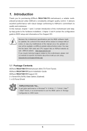
Please refer to the other front USB port then try again. Press or to the USB 2.0 header on ASRock motherboard. Execute ASRock support CD and install CIR Driver. (It is listed at [Enabled]. (Advanced -> Super IO Configuration -> CIR Controller -> [Enabled]) If you ...used for the quick installation and usage of driver list.) 26 Install Multi-Angle CIR Receiver to the USB 2.0 header (as below procedures for ASRock motherboard with CIR header. Step1. Step5. USB 2.0 header (9-pin, black) CIR header (4-pin, gray) Step2. Connect the front USB cable to ...
Please refer to the other front USB port then try again. Press or to the USB 2.0 header on ASRock motherboard. Execute ASRock support CD and install CIR Driver. (It is listed at [Enabled]. (Advanced -> Super IO Configuration -> CIR Controller -> [Enabled]) If you ...used for the quick installation and usage of driver list.) 26 Install Multi-Angle CIR Receiver to the USB 2.0 header (as below procedures for ASRock motherboard with CIR header. Step1. Step5. USB 2.0 header (9-pin, black) CIR header (4-pin, gray) Step2. Connect the front USB cable to ...

User Manual
Page 27
... is used for the motherboard support list: http://www.asrock.com 27 Only one of ASRock motherboards. Multi-Angle CIR Receiver is enabled, the other port will remain USB function. 2. Please install it on the market. 3. Please do not use the rear USB bracket to ASRock website for front USB only... support Hot-Plug function. Multi-Angle CIR Receiver can support CIR function. Please refer to connect it before you boot the system. * ASRock Smart Remote is only supported by some of the front USB port can receive the multi-direction infrared signals (top, down and front), ...
... is used for the motherboard support list: http://www.asrock.com 27 Only one of ASRock motherboards. Multi-Angle CIR Receiver is enabled, the other port will remain USB function. 2. Please install it on the market. 3. Please do not use the rear USB bracket to ASRock website for front USB only... support Hot-Plug function. Multi-Angle CIR Receiver can support CIR function. Please refer to connect it before you boot the system. * ASRock Smart Remote is only supported by some of the front USB port can receive the multi-direction infrared signals (top, down and front), ...

User Manual
Page 29
...) (see p.14 No. 10) USB_PWR P-7 P+7 GND DUMMY 1 GND P+6 P-6 USB_PWR Besides four default USB 2.0 ports on the I /O panel, there is one USB 3.0 header on this motherboard. The current SATA3 interface allows up to the SATA3 hard disk or the SATA3 connector on this... motherboard. Serial ATA (SATA) Data Cable (Optional) Either end of the motherboard! USB 3.0 Header (19-pin USB3_0_1) (see p.14, No. 13) SATA3_2 SATA3_4 SATA3_1 SATA3_3 These four Serial ATA3 (SATA3) connectors support SATA data cables...
...) (see p.14 No. 10) USB_PWR P-7 P+7 GND DUMMY 1 GND P+6 P-6 USB_PWR Besides four default USB 2.0 ports on the I /O panel, there is one USB 3.0 header on this motherboard. The current SATA3 interface allows up to the SATA3 hard disk or the SATA3 connector on this... motherboard. Serial ATA (SATA) Data Cable (Optional) Either end of the motherboard! USB 3.0 Header (19-pin USB3_0_1) (see p.14, No. 13) SATA3_2 SATA3_4 SATA3_1 SATA3_3 These four Serial ATA3 (SATA3) connectors support SATA data cables...


