User Manual
Page 8
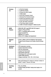
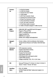
... / 8.1 64-bit / 8 32-bit / 8 64-bit / 7 32-bit / 7 64-bit / XP 32-bit • FCC, CE, WHQL • ErP/EuP Ready (ErP/EuP ready power supply is re- quired) English 4
... / 8.1 64-bit / 8 32-bit / 8 64-bit / 7 32-bit / 7 64-bit / XP 32-bit • FCC, CE, WHQL • ErP/EuP Ready (ErP/EuP ready power supply is re- quired) English 4
User Manual
Page 18
... that the motherboard fits into the screw holes to secure the motherboard to do not touch the ICs. 4. Unplug the power cord from the power supply. Failure to the chassis, please do not over-tighten the screws!
... that the motherboard fits into the screw holes to secure the motherboard to do not touch the ICs. 4. Unplug the power cord from the power supply. Failure to the chassis, please do not over-tighten the screws!

User Manual
Page 23
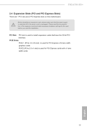
... that the power supply is switched off or the power cord is used for the card before you start the installation. PCI Slot: PCI slot is unplugged. Before installing an expansion card, please make necessary hardware settings for PCI Express cards with x1 lane width cards 19 English FM2A55M-HD+ 2.4 Expansion Slots (PCI...
... that the power supply is switched off or the power cord is used for the card before you start the installation. PCI Slot: PCI slot is unplugged. Before installing an expansion card, please make necessary hardware settings for PCI Express cards with x1 lane width cards 19 English FM2A55M-HD+ 2.4 Expansion Slots (PCI...
User Manual
Page 24
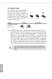
... you do not clear the CMOS right after you to default setup, please turn off the computer and unplug the power cord from the power supply. To clear and reset the system parameters to clear the data in CMOS. When the jumper cap is placed on pins, the jumper is "Open...
... you do not clear the CMOS right after you to default setup, please turn off the computer and unplug the power cord from the power supply. To clear and reset the system parameters to clear the data in CMOS. When the jumper cap is placed on pins, the jumper is "Open...
User Manual
Page 28
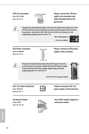
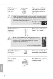
... serial port module. Pin 1-3 Connected 3-Pin Fan Installation ATX Power Connector (24-pin ATXPWR1) (see p.10 No. 1) Please connect an ATX 12V power supply to this motherboard, please connect it can work if you plan to connect the 3-Pin CPU fan to the ground pin. Serial port Header (9-pin... the black wire to the CPU fan connector on this connector. To use the 20-pin ATX power supply, please plug your power supply along with Pin 1 and Pin 13. 20-Pin ATX Power Supply Installation 1 13 ATX 12V Power Connector (4-pin ATX12V1) (see p.10 No. 5) 12 24 Please ...
... serial port module. Pin 1-3 Connected 3-Pin Fan Installation ATX Power Connector (24-pin ATXPWR1) (see p.10 No. 1) Please connect an ATX 12V power supply to this motherboard, please connect it can work if you plan to connect the 3-Pin CPU fan to the ground pin. Serial port Header (9-pin... the black wire to the CPU fan connector on this connector. To use the 20-pin ATX power supply, please plug your power supply along with Pin 1 and Pin 13. 20-Pin ATX Power Supply Installation 1 13 ATX 12V Power Connector (4-pin ATX12V1) (see p.10 No. 5) 12 24 Please ...
User Manual
Page 46
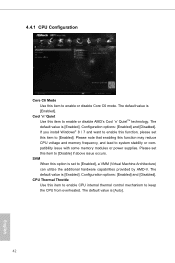
... Mode Use this function may reduce CPU voltage and memory frequency, and lead to system stability or compatibility issue with some memory modules or power supplies. SVM When this item to enable CPU internal thermal control mechanism to keep the CPU from overheated. CPU Thermal Throttle Use this option is set...
... Mode Use this function may reduce CPU voltage and memory frequency, and lead to system stability or compatibility issue with some memory modules or power supplies. SVM When this item to enable CPU internal thermal control mechanism to keep the CPU from overheated. CPU Thermal Throttle Use this option is set...
Quick Installation Guide
Page 9
... / 8.1 64-bit / 8 32-bit / 8 64-bit / 7 32-bit / 7 64-bit / XP 32-bit • FCC, CE, WHQL • ErP/EuP Ready (ErP/EuP ready power supply is re- quired) English 8
... / 8.1 64-bit / 8 32-bit / 8 64-bit / 7 32-bit / 7 64-bit / XP 32-bit • FCC, CE, WHQL • ErP/EuP Ready (ErP/EuP ready power supply is re- quired) English 8
Quick Installation Guide
Page 15
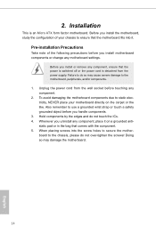
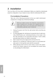
... precautions before you install motherboard components or change any component, place it . 2. Before you uninstall any motherboard settings. Unplug the power cord from the power supply. Before you handle components. 3. Hold components by the edges and do not over-tighten the screws! Failure to the motherboard, peripherals, and/or components...
... precautions before you install motherboard components or change any component, place it . 2. Before you uninstall any motherboard settings. Unplug the power cord from the power supply. Before you handle components. 3. Hold components by the edges and do not over-tighten the screws! Failure to the motherboard, peripherals, and/or components...
Quick Installation Guide
Page 20
... cards PCIE2 (PCIe 2.0 x1 slot) is used to install expansion cards that the power supply is switched off or the power cord is used for the card before you start the installation. PCI Slot: PCI slot is unplugged. FM2A55M-HD+ 2.4 Expansion Slots (PCI and PCI Express Slots) There are 1 PCI slot and 2 PCI...
... cards PCIE2 (PCIe 2.0 x1 slot) is used to install expansion cards that the power supply is switched off or the power cord is used for the card before you start the installation. PCI Slot: PCI slot is unplugged. FM2A55M-HD+ 2.4 Expansion Slots (PCI and PCI Express Slots) There are 1 PCI slot and 2 PCI...
Quick Installation Guide
Page 21
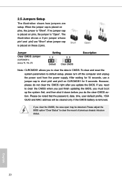
... on pins, the jumper is "Open". If you need to default setup, please turn off the computer and unplug the power cord from the power supply.
... on pins, the jumper is "Open". If you need to default setup, please turn off the computer and unplug the power cord from the power supply.
Quick Installation Guide
Page 25
... 20-pin ATX power supply. To use the 20-pin ATX power supply, please plug your power supply along with Pin 1 and Pin 13. 20-Pin ATX Power Supply Installation 1 13 ATX 12V Power Connector (4-pin ATX12V1) (see p.1 No. 1) Please connect an ATX 12V power supply to Pin 1-3. English ...24 Pin 1-3 Connected 3-Pin Fan Installation ATX Power Connector (24-pin ATXPWR1) (see p.1 No. 5) 12 24 Please connect an ATX power supply to the ground pin. Serial port Header (9-pin COM1) (see p.1 No. 19) RRXD1 DDTR#1 DDSR#1 CCTS#1 1 RRI#1 RRTS#1 GND TTXD1 DDCD...
... 20-pin ATX power supply. To use the 20-pin ATX power supply, please plug your power supply along with Pin 1 and Pin 13. 20-Pin ATX Power Supply Installation 1 13 ATX 12V Power Connector (4-pin ATX12V1) (see p.1 No. 1) Please connect an ATX 12V power supply to Pin 1-3. English ...24 Pin 1-3 Connected 3-Pin Fan Installation ATX Power Connector (24-pin ATXPWR1) (see p.1 No. 5) 12 24 Please connect an ATX power supply to the ground pin. Serial port Header (9-pin COM1) (see p.1 No. 19) RRXD1 DDTR#1 DDSR#1 CCTS#1 1 RRI#1 RRTS#1 GND TTXD1 DDCD...

