
User Manual
Page 3
...1 1.2 Specifications 2 1.3 Motherboard Layout 5 1.4 I/O Panel 7 Chapter 2 Installation 8 2.1 Installing the CPU 9 2.2 Installing the CPU Fan and Heatsink 12 2.3 Installing Memory Modules (DIMM) 13 2.4 Expansion Slots (PCI Express Slots) 15 2.5 Jumpers Setup 16 2.6 Onboard Headers and Connectors 17 Chapter 3 Software and Utilities Operation 22 3.1 Installing Drivers 22 3.2 A-Tuning 23 3.3 Intel® Rapid Start Technology 29 3.4 Intel® Smart Connect Technology 34 3.5 ASRock Cloud 39 3.6 ASRock APP Shop 49 3.6.1 UI Overview 49 3.6.2 Apps 50 3.6.3 BIOS...
...1 1.2 Specifications 2 1.3 Motherboard Layout 5 1.4 I/O Panel 7 Chapter 2 Installation 8 2.1 Installing the CPU 9 2.2 Installing the CPU Fan and Heatsink 12 2.3 Installing Memory Modules (DIMM) 13 2.4 Expansion Slots (PCI Express Slots) 15 2.5 Jumpers Setup 16 2.6 Onboard Headers and Connectors 17 Chapter 3 Software and Utilities Operation 22 3.1 Installing Drivers 22 3.2 A-Tuning 23 3.3 Intel® Rapid Start Technology 29 3.4 Intel® Smart Connect Technology 34 3.5 ASRock Cloud 39 3.6 ASRock APP Shop 49 3.6.1 UI Overview 49 3.6.2 Apps 50 3.6.3 BIOS...
User Manual
Page 5
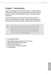
... control. ASRock website http://www.asrock.com. 1.1 Package Contents • ASRock B95M-DGS Motherboard (Micro ATX Form Factor) • ASRock B95M-DGS Quick Installation Guide • ASRock B95M-DGS Support CD • 2 x Serial ATA (SATA) Data Cables (Optional) • 1 x I/O Panel Shield 1 English In case any modifications of the motherboard and step-by-step installation guides. Chapter 3 contains the operation guide of the BIOS setup. You may find the latest VGA cards and CPU support list on ASRock's website without notice. Because the motherboard specifications...
... control. ASRock website http://www.asrock.com. 1.1 Package Contents • ASRock B95M-DGS Motherboard (Micro ATX Form Factor) • ASRock B95M-DGS Quick Installation Guide • ASRock B95M-DGS Support CD • 2 x Serial ATA (SATA) Data Cables (Optional) • 1 x I/O Panel Shield 1 English In case any modifications of the motherboard and step-by-step installation guides. Chapter 3 contains the operation guide of the BIOS setup. You may find the latest VGA cards and CPU support list on ASRock's website without notice. Because the motherboard specifications...

User Manual
Page 7
...; 2 x USB 3.0 Ports (Supports ESD Protection (ASRock Full Spike Protection)) • 1 x RJ-45 LAN Port with LED (ACT/LINK LED and SPEED LED) • HD Audio Jacks: Line in / Front Speaker / Microphone Storage • 4 x SATA3 6.0 Gb/s Connectors, support NCQ, AHCI and Hot Plug Connector • 1 x Print Port Header • 1 x COM Port Header • 1 x Chassis Intrusion Header • 1 x TPM Header • 1 x CPU Fan Connector (4-pin) • 1 x Chassis Fan Connector (4-pin) • 1 x Power Fan Connector (3-pin) • 1 x 24 pin ATX Power Connector • 1 x 4 pin 12V Power...
...; 2 x USB 3.0 Ports (Supports ESD Protection (ASRock Full Spike Protection)) • 1 x RJ-45 LAN Port with LED (ACT/LINK LED and SPEED LED) • HD Audio Jacks: Line in / Front Speaker / Microphone Storage • 4 x SATA3 6.0 Gb/s Connectors, support NCQ, AHCI and Hot Plug Connector • 1 x Print Port Header • 1 x COM Port Header • 1 x Chassis Intrusion Header • 1 x TPM Header • 1 x CPU Fan Connector (4-pin) • 1 x Chassis Fan Connector (4-pin) • 1 x Power Fan Connector (3-pin) • 1 x 24 pin ATX Power Connector • 1 x 4 pin 12V Power...

User Manual
Page 8
... USB 3.0 Header (Supports 2 USB 3.0 ports) (Supports ESD Protection (ASRock Full Spike Protection)) • 32Mb AMI UEFI Legal BIOS with overclocking, including adjusting the setting in the BIOS, applying Untied Overclocking Technology, or using thirdparty overclocking tools. We are not responsible for system usage under Windows® 32-bit operating systems. Windows® 64-bit operating systems do not have such limitations. ment • CPU/Chassis temperature sensing • CPU/Chassis/Power Fan Tachometer • CPU/Chassis Quiet Fan (Auto adjust chassis fan speed by overclocking...
... USB 3.0 Header (Supports 2 USB 3.0 ports) (Supports ESD Protection (ASRock Full Spike Protection)) • 32Mb AMI UEFI Legal BIOS with overclocking, including adjusting the setting in the BIOS, applying Untied Overclocking Technology, or using thirdparty overclocking tools. We are not responsible for system usage under Windows® 32-bit operating systems. Windows® 64-bit operating systems do not have such limitations. ment • CPU/Chassis temperature sensing • CPU/Chassis/Power Fan Tachometer • CPU/Chassis Quiet Fan (Auto adjust chassis fan speed by overclocking...

User Manual
Page 19
PCIE2 (PCIe 2.0 x1 slot) is used for PCI Express x1 lane width graphics cards. 15 English PCIe slots: PCIE1 (PCIe 3.0 x16 slot) is unplugged. B95M-DGS 2.4 Expansion Slots (PCI Express Slots) There are 2 PCI Express slots on the motherboard. Before installing an expansion card, please make necessary hardware settings for the card before you start the installation. Please read the documentation of the expansion card and make sure that the power supply is switched off or the power cord is used for PCI Express x16 lane width graphics cards.
PCIE2 (PCIe 2.0 x1 slot) is used for PCI Express x1 lane width graphics cards. 15 English PCIe slots: PCIE1 (PCIe 3.0 x16 slot) is unplugged. B95M-DGS 2.4 Expansion Slots (PCI Express Slots) There are 2 PCI Express slots on the motherboard. Before installing an expansion card, please make necessary hardware settings for the card before you start the installation. Please read the documentation of the expansion card and make sure that the power supply is switched off or the power cord is used for PCI Express x16 lane width graphics cards.

User Manual
Page 20
... previous chassis intrusion status. After waiting for 15 seconds, use a jumper cap to short pin2 and pin3 on the pins, the jumper is removed. Please adjust the BIOS option "Clear Status" to default setup, please turn off the computer and unplug the power cord from the power supply. The illustration shows a 3-pin jumper whose pin1 and pin2 are setup. Clear CMOS Jumper (CLRCMOS1) (see p.5, No. 11) Default Clear CMOS CLRCMOS1 allows you clear the CMOS, the case open...
... previous chassis intrusion status. After waiting for 15 seconds, use a jumper cap to short pin2 and pin3 on the pins, the jumper is removed. Please adjust the BIOS option "Clear Status" to default setup, please turn off the computer and unplug the power cord from the power supply. The illustration shows a 3-pin jumper whose pin1 and pin2 are setup. Clear CMOS Jumper (CLRCMOS1) (see p.5, No. 11) Default Clear CMOS CLRCMOS1 allows you clear the CMOS, the case open...

User Manual
Page 21
... panel design may configure the way to the reset switch on the chassis front panel. PWRBTN (Power Switch): Connect to the hard drive activity LED on the chassis front panel. The LED keeps blinking when the system is in S1/S3 sleep state. Note the positive and negative pins before connecting the cables. HDLED (Hard Drive Activity LED): Connect to the power switch on the chassis front panel. A front panel module mainly consists of power switch, reset switch, power LED, hard drive activity LED, speaker and etc. B95M-DGS 2.6 Onboard Headers and Connectors Onboard headers and connectors...
... panel design may configure the way to the reset switch on the chassis front panel. PWRBTN (Power Switch): Connect to the hard drive activity LED on the chassis front panel. The LED keeps blinking when the system is in S1/S3 sleep state. Note the positive and negative pins before connecting the cables. HDLED (Hard Drive Activity LED): Connect to the power switch on the chassis front panel. A front panel module mainly consists of power switch, reset switch, power LED, hard drive activity LED, speaker and etc. B95M-DGS 2.6 Onboard Headers and Connectors Onboard headers and connectors...
User Manual
Page 23
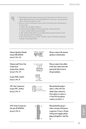
... manual and chassis manual to install your system. 2. Chassis Speaker Header (4-pin SPEAKER1) (see p.5, No. 5) 12 24 1 13 This motherboard provides a 24-pin ATX power connector. To use an AC'97 audio panel, please install it to Ground (GND). MIC_RET and OUT_RET are for the AC'97 audio panel. B95M-DGS 1. Please follow the instructions in the Realtek Control panel and adjust "Recording Volume". GND +12V FAN_SPEED 1 GND This motherboard pro- 2 +12V 3 FAN_SPEED vides a 4-Pin CPU fan 4 FAN_SPEED_CONTROL (Quiet Fan) connector...
... manual and chassis manual to install your system. 2. Chassis Speaker Header (4-pin SPEAKER1) (see p.5, No. 5) 12 24 1 13 This motherboard provides a 24-pin ATX power connector. To use an AC'97 audio panel, please install it to Ground (GND). MIC_RET and OUT_RET are for the AC'97 audio panel. B95M-DGS 1. Please follow the instructions in the Realtek Control panel and adjust "Recording Volume". GND +12V FAN_SPEED 1 GND This motherboard pro- 2 +12V 3 FAN_SPEED vides a 4-Pin CPU fan 4 FAN_SPEED_CONTROL (Quiet Fan) connector...
User Manual
Page 26
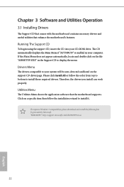
... your computer. If the Main Menu does not appear automatically, locate and double click on the file "ASRSETUP.EXE" in your CD-ROM drive. "KB2720599": http://support.microsoft.com/kb/2720599/en-us 22 English Chapter 3 Software and Utilities Operation 3.1 Installing Drivers The Support CD that comes with the motherboard contains necessary drivers and useful utilities that the motherboard supports. To improve Windows 7 compatibility, please download and install the following hot fix...
... your computer. If the Main Menu does not appear automatically, locate and double click on the file "ASRSETUP.EXE" in your CD-ROM drive. "KB2720599": http://support.microsoft.com/kb/2720599/en-us 22 English Chapter 3 Software and Utilities Operation 3.1 Installing Drivers The Support CD that comes with the motherboard contains necessary drivers and useful utilities that the motherboard supports. To improve Windows 7 compatibility, please download and install the following hot fix...
User Manual
Page 29
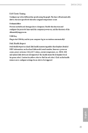
... to be triggered. 25 English HDD, SSD and optical disk drives are all supported. Click on the health status icon to configure settings for an alert to windows automatically! values, current temperature, etc. The fans will automatically shift to the next speed level when the assigned temperature is a hard disk health monitoring utility that displays detailed HDD information, such as hard disk model, serial number, firmware, power on count, power on , and the duration...
... to be triggered. 25 English HDD, SSD and optical disk drives are all supported. Click on the health status icon to configure settings for an alert to windows automatically! values, current temperature, etc. The fans will automatically shift to the next speed level when the assigned temperature is a hard disk health monitoring utility that displays detailed HDD information, such as hard disk model, serial number, firmware, power on count, power on , and the duration...

User Manual
Page 38
... your motherboard supports this feature. • Operating system: Microsoft Windows 8.1/8/7 (32- There are certain risks. or 64-bit edition) • Set the SATA mode to avoid loss. 1. Click on the value Start and change the value from Windows® sleep state to crash while booting. Please backup any important data before operating to AHCI. Enter into HKEY_LOCAL_MACHINE\SYSTEM\CurrentControlSet\services\ msahci in AHCI mode, please follow the instructions...
... your motherboard supports this feature. • Operating system: Microsoft Windows 8.1/8/7 (32- There are certain risks. or 64-bit edition) • Set the SATA mode to avoid loss. 1. Click on the value Start and change the value from Windows® sleep state to crash while booting. Please backup any important data before operating to AHCI. Enter into HKEY_LOCAL_MACHINE\SYSTEM\CurrentControlSet\services\ msahci in AHCI mode, please follow the instructions...

User Manual
Page 73
B95M-DGS 4.4 Advanced Screen In this section may set the configurations for the following items: CPU Configuration, Chipset Configuration, Storage Configuration, Intel® Rapid Start Technology, Intel® Smart Connect Technology, Super IO Configuration, ACPI Configuration, USB Configuration and Trusted Computing. Setting wrong values in this section, you may cause the system to malfunction. 69 English
B95M-DGS 4.4 Advanced Screen In this section may set the configurations for the following items: CPU Configuration, Chipset Configuration, Storage Configuration, Intel® Rapid Start Technology, Intel® Smart Connect Technology, Super IO Configuration, ACPI Configuration, USB Configuration and Trusted Computing. Setting wrong values in this section, you may cause the system to malfunction. 69 English

User Manual
Page 76
... integrated graphics enabled at all times. Select enable to disable the integrated graphics when an external graphics card is installed. PCIE1 Link Speed Select the link speed for lower power consumption. 72 English Render Standby Power down the render unit when the GPU is allocated to the integrated graphics processor when the system boots up. VT-d Intel® Virtualization Technology for Directed I/O helps your virtual machine monitor better utilize hardware...
... integrated graphics enabled at all times. Select enable to disable the integrated graphics when an external graphics card is installed. PCIE1 Link Speed Select the link speed for lower power consumption. 72 English Render Standby Power down the render unit when the GPU is allocated to the integrated graphics processor when the system boots up. VT-d Intel® Virtualization Technology for Directed I/O helps your virtual machine monitor better utilize hardware...

User Manual
Page 77
Set to Auto to boot up when the power recovers. It will start to enable onboard HD audio and automatically disable it is selected, the system will also automatically switch off the Power and Keyboard LEDs when the system enters into Standby/Hibernation mode. 73 English Onboard LAN Enable or disable the onboard network interface controller. Good Night LED By enabling Good Night LED, the Power/HDD LEDs will be disabled. B95M-DGS Onboard HD Audio Enable/disable onboard HD audio. If you disable iCafe Audio, the headphone amplifier for...
Set to Auto to boot up when the power recovers. It will start to enable onboard HD audio and automatically disable it is selected, the system will also automatically switch off the Power and Keyboard LEDs when the system enters into Standby/Hibernation mode. 73 English Onboard LAN Enable or disable the onboard network interface controller. Good Night LED By enabling Good Night LED, the Power/HDD LEDs will be disabled. B95M-DGS Onboard HD Audio Enable/disable onboard HD audio. If you disable iCafe Audio, the headphone amplifier for...

User Manual
Page 81
Parallel Port Enable or disable the Parallel port. 4.4.6 Super IO Configuration B95M-DGS PS2 Y-Cable Enable the PS2 Y-Cable or set this option to your connected device. 77 English Serial Port Enable or disable the Serial port. Device Mode Select the device mode according to Auto. Change Settings Select the address of the Serial port. Serial Port Address Select the address of the Parallel port.
Parallel Port Enable or disable the Parallel port. 4.4.6 Super IO Configuration B95M-DGS PS2 Y-Cable Enable the PS2 Y-Cable or set this option to your connected device. 77 English Serial Port Enable or disable the Serial port. Device Mode Select the device mode according to Auto. Change Settings Select the address of the Serial port. Serial Port Address Select the address of the Parallel port.

User Manual
Page 84
... enable the USB 3.0 driver after rebooting (USB 3.0 is disabled in BIOS). Set [Auto] to use USB devices under the UEFI setup and Windows/Linux operating systems only. Legacy USB 3.0 Support Enable or disable Legacy OS Support for USB 2.0 devices. Set [Disabled] to support USB devices under the UEFI setup and Windows/Linux operating systems only. 80 English Intel USB 3.0 Mode Select Intel® USB 3.0 controller mode. Legacy USB Support Enable or disable Legacy OS Support for USB 3.0 devices. Select UEFI Setup Only to keep the USB 3.0 driver enabled after entering the OS (USB...
... enable the USB 3.0 driver after rebooting (USB 3.0 is disabled in BIOS). Set [Auto] to use USB devices under the UEFI setup and Windows/Linux operating systems only. Legacy USB 3.0 Support Enable or disable Legacy OS Support for USB 2.0 devices. Set [Disabled] to support USB devices under the UEFI setup and Windows/Linux operating systems only. 80 English Intel USB 3.0 Mode Select Intel® USB 3.0 controller mode. Legacy USB Support Enable or disable Legacy OS Support for USB 3.0 devices. Select UEFI Setup Only to keep the USB 3.0 driver enabled after entering the OS (USB...
User Manual
Page 87
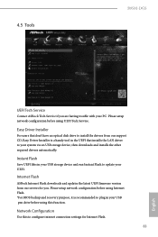
... UEFI firmware version from our support CD, Easy Driver Installer is recommended to update your USB pen drive before using UEFI Tech Service. Please setup network configuration before using Internet Flash. *For BIOS backup and recovery purpose, it is a handy tool in your UEFI. Instant Flash Save UEFI files in your USB storage device and run Instant Flash to plug in the UEFI that don't have an optical disk drive to install the drivers from our servers for Internet Flash. 83 English 4.5 Tools B95M-DGS UEFI Tech Service...
... UEFI firmware version from our support CD, Easy Driver Installer is recommended to update your USB pen drive before using UEFI Tech Service. Please setup network configuration before using Internet Flash. *For BIOS backup and recovery purpose, it is a handy tool in your UEFI. Instant Flash Save UEFI files in your USB storage device and run Instant Flash to plug in the UEFI that don't have an optical disk drive to install the drivers from our servers for Internet Flash. 83 English 4.5 Tools B95M-DGS UEFI Tech Service...

Quick Installation Guide
Page 9
... x USB 3.0 Header (Supports 2 USB 3.0 ports) (Supports ESD Protection (ASRock Full Spike Protection)) • 32Mb AMI UEFI Legal BIOS with overclocking, including adjusting the setting in the BIOS, applying Untied Overclocking Technology, or using thirdparty overclocking tools. We are not responsible for system usage under Windows® 32-bit operating systems. Windows® 64-bit operating systems do not have such limitations. ment • CPU/Chassis temperature sensing • CPU/Chassis/Power Fan Tachometer • CPU/Chassis Quiet Fan (Auto adjust chassis fan speed by overclocking...
... x USB 3.0 Header (Supports 2 USB 3.0 ports) (Supports ESD Protection (ASRock Full Spike Protection)) • 32Mb AMI UEFI Legal BIOS with overclocking, including adjusting the setting in the BIOS, applying Untied Overclocking Technology, or using thirdparty overclocking tools. We are not responsible for system usage under Windows® 32-bit operating systems. Windows® 64-bit operating systems do not have such limitations. ment • CPU/Chassis temperature sensing • CPU/Chassis/Power Fan Tachometer • CPU/Chassis Quiet Fan (Auto adjust chassis fan speed by overclocking...

Quick Installation Guide
Page 10
... BIOS option "Clear Status" to default setup, please turn off the computer and unplug the power cord from the power supply. When the jumper cap is placed on the pins, the jumper is removed. If you to clear the data in CMOS. Clear CMOS Jumper (CLRCMOS1) (see p.1, No. 11) Default Clear CMOS CLRCMOS1 allows you clear the CMOS, the case open may be cleared only if the CMOS battery is "Short". After waiting for 15 seconds, use a jumper cap to clear...
... BIOS option "Clear Status" to default setup, please turn off the computer and unplug the power cord from the power supply. When the jumper cap is placed on the pins, the jumper is removed. If you to clear the data in CMOS. Clear CMOS Jumper (CLRCMOS1) (see p.1, No. 11) Default Clear CMOS CLRCMOS1 allows you clear the CMOS, the case open may be cleared only if the CMOS battery is "Short". After waiting for 15 seconds, use a jumper cap to clear...

Quick Installation Guide
Page 13
... instructions in the Realtek Control panel and adjust "Recording Volume". MIC_RET and OUT_RET are for the AC'97 audio panel. If you use a 20-pin ATX power supply, please plug it to OUT2_L. B95M-DGS 1. D. To activate the front mic, go to the ground pin. Chassis and Power Fan Connectors (4-pin CHA_FAN1) (see p.1, No. 17) (3-pin PWR_FAN1) (see p.1, No. 3) CPU Fan Connector (4-pin CPU_FAN1) (see p.1, No. 1) FAN_SPEED_CONTROL FAN_SPEED +12V GND 1 234 Please connect fan cables to the fan connectors...
... instructions in the Realtek Control panel and adjust "Recording Volume". MIC_RET and OUT_RET are for the AC'97 audio panel. If you use a 20-pin ATX power supply, please plug it to OUT2_L. B95M-DGS 1. D. To activate the front mic, go to the ground pin. Chassis and Power Fan Connectors (4-pin CHA_FAN1) (see p.1, No. 17) (3-pin PWR_FAN1) (see p.1, No. 3) CPU Fan Connector (4-pin CPU_FAN1) (see p.1, No. 1) FAN_SPEED_CONTROL FAN_SPEED +12V GND 1 234 Please connect fan cables to the fan connectors...


