
RAID Installation Guide
Page 2
... of the "User Manual" in our support CD, then you to read and write data in the other drive if one drive fails. 2 It provides data protection and increases fault tolerance to the entire system since it does not provide any HDDs of the same model and capacity when creating a RAID set the option to RAID mode by using the onboard FastBuild BIOS utility under BIOS environment...
... of the "User Manual" in our support CD, then you to read and write data in the other drive if one drive fails. 2 It provides data protection and increases fault tolerance to the entire system since it does not provide any HDDs of the same model and capacity when creating a RAID set the option to RAID mode by using the onboard FastBuild BIOS utility under BIOS environment...

RAID Installation Guide
Page 8
...ROM. Plug a USB drive into your USB flash drive. 8 STEP 4: Windows installation A. During system boot, press or key to finish the driver copy process. Please download the "SATA Floppy Imaged driver" from ASRock's website A. Insert the Support CD into the DVD-ROM drive. E. B. C. Follow instructions to enter UEFI setup utility. A. During Windows installation process, when Disk selection page show up, please click . Go to finish the configuration. STEP 3.2: Download driver from ASRock's website and unzip the file into one of the USB port. STEP 3.1: Copy RAID driver...
...ROM. Plug a USB drive into your USB flash drive. 8 STEP 4: Windows installation A. During system boot, press or key to finish the driver copy process. Please download the "SATA Floppy Imaged driver" from ASRock's website A. Insert the Support CD into the DVD-ROM drive. E. B. C. Follow instructions to enter UEFI setup utility. A. During Windows installation process, when Disk selection page show up, please click . Go to finish the configuration. STEP 3.2: Download driver from ASRock's website and unzip the file into one of the USB port. STEP 3.1: Copy RAID driver...

RAID Installation Guide
Page 12
During system boot, press or key to Tools Easy RAID Installer F. D. C. Go to enter UEFI setup utility. Please download the "SATA Floppy Imaged driver" from ASRock's website A. B. A. Go to AdvancedRAIDXpert2 Configuration UtilityArray ManagementCreate Array Select Physical DisksCheck AllApply ChangesCreate Array. *Be sure to exit. Plug a USB drive into the DVD-ROM drive. Click to save to delete the existing disk arrays...
During system boot, press or key to Tools Easy RAID Installer F. D. C. Go to enter UEFI setup utility. Please download the "SATA Floppy Imaged driver" from ASRock's website A. B. A. Go to AdvancedRAIDXpert2 Configuration UtilityArray ManagementCreate Array Select Physical DisksCheck AllApply ChangesCreate Array. *Be sure to exit. Plug a USB drive into the DVD-ROM drive. Click to save to delete the existing disk arrays...
User Manual
Page 4
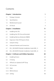
... 1.4 I/O Panel 9 Chapter 2 Installation 11 2.1 Installing the CPU 12 2.2 Installing the CPU Fan and Heatsink 14 2.3 Installing Memory Modules (DIMM) 23 2.4 Expansion Slots (PCI Express Slots) 26 2.5 Jumpers Setup 27 2.6 Onboard Headers and Connectors 28 2.7 M.2_SSD (NGFF) Module Installation Guide (M2_1) 33 2.8 M.2_SSD (NGFF) Module Installation Guide (M2_2) 36 Chapter 3 Software and Utilities Operation 39 3.1 Installing Drivers 39 3.2 A-Tuning 40 3.3 ASRock Live Update & APP Shop 43 3.3.1 UI Overview 43 3.3.2 Apps 44 3.3.3 BIOS & Drivers 47 3.3.4 Setting 48
... 1.4 I/O Panel 9 Chapter 2 Installation 11 2.1 Installing the CPU 12 2.2 Installing the CPU Fan and Heatsink 14 2.3 Installing Memory Modules (DIMM) 23 2.4 Expansion Slots (PCI Express Slots) 26 2.5 Jumpers Setup 27 2.6 Onboard Headers and Connectors 28 2.7 M.2_SSD (NGFF) Module Installation Guide (M2_1) 33 2.8 M.2_SSD (NGFF) Module Installation Guide (M2_2) 36 Chapter 3 Software and Utilities Operation 39 3.1 Installing Drivers 39 3.2 A-Tuning 40 3.3 ASRock Live Update & APP Shop 43 3.3.1 UI Overview 43 3.3.2 Apps 44 3.3.3 BIOS & Drivers 47 3.3.4 Setting 48
User Manual
Page 6
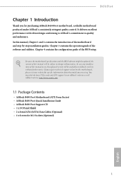
...to ASRock's commitment to change without further notice. ASRock website http://www.asrock.com. 1.1 Package Contents • ASRock B450 Pro4 Motherboard (ATX Form Factor) • ASRock B450 Pro4 Quick Installation Guide • ASRock B450 Pro4 Support CD • 1 x I/O Panel Shield • 2 x Serial ATA (SATA) Data Cables (Optional) • 2 x Screws for purchasing ASRock B450 Pro4 motherboard, a reliable motherboard produced under ASRock's consistently stringent quality control. In this motherboard, please visit our website for specific information about the model you are using.
...to ASRock's commitment to change without further notice. ASRock website http://www.asrock.com. 1.1 Package Contents • ASRock B450 Pro4 Motherboard (ATX Form Factor) • ASRock B450 Pro4 Quick Installation Guide • ASRock B450 Pro4 Support CD • 1 x I/O Panel Shield • 2 x Serial ATA (SATA) Data Cables (Optional) • 2 x Screws for purchasing ASRock B450 Pro4 motherboard, a reliable motherboard produced under ASRock's consistently stringent quality control. In this motherboard, please visit our website for specific information about the model you are using.
User Manual
Page 10
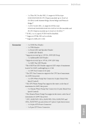
... disks ** Supports ASRock U.2 Kit Connector • 1 x COM Port Header • 1 x TPM Header • 1 x Power LED and Speaker Header • 1 x RGB LED Header * Supports in total up to 12V/3A, 36W LED Strip • 1 x Addressable LED Header * Supports in total up to 5V/3A, 15W LED Strip • 1 x AMD Fan LED Header *The AMD Fan LED Header supports LED strips of maximum load of 3A (36W) and length up to 2.5M. • 1 x CPU Fan Connector (4-pin) * The CPU Fan Connector supports the CPU fan of maximum 1A (12W) fan power. • 1 x CPU/Water Pump Fan Connector (4-pin) (Smart Fan Speed...
... disks ** Supports ASRock U.2 Kit Connector • 1 x COM Port Header • 1 x TPM Header • 1 x Power LED and Speaker Header • 1 x RGB LED Header * Supports in total up to 12V/3A, 36W LED Strip • 1 x Addressable LED Header * Supports in total up to 5V/3A, 15W LED Strip • 1 x AMD Fan LED Header *The AMD Fan LED Header supports LED strips of maximum load of 3A (36W) and length up to 2.5M. • 1 x CPU Fan Connector (4-pin) * The CPU Fan Connector supports the CPU fan of maximum 1A (12W) fan power. • 1 x CPU/Water Pump Fan Connector (4-pin) (Smart Fan Speed...
User Manual
Page 11
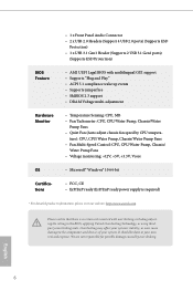
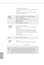
...8226; DRAM Voltage multi-adjustment Hardware Monitor • Temperature Sensing: CPU, MB • Fan Tachometer: CPU, CPU/Water Pump, Chassis/Water Pump Fans • Quiet Fan (Auto adjust chassis fan speed by overclocking. • 1 x Front Panel Audio Connector • 2 x USB 2.0 Headers (Support 4 USB 2.0 ports) (Supports ESD Protection) • 1 x USB 3.1 Gen1 Header (Supports 2 USB 3.1 Gen1 ports) (Supports ESD Protection) BIOS Feature • AMI UEFI Legal BIOS with overclocking, including adjusting the setting in the BIOS, applying Untied Overclocking Technology, or using...
...8226; DRAM Voltage multi-adjustment Hardware Monitor • Temperature Sensing: CPU, MB • Fan Tachometer: CPU, CPU/Water Pump, Chassis/Water Pump Fans • Quiet Fan (Auto adjust chassis fan speed by overclocking. • 1 x Front Panel Audio Connector • 2 x USB 2.0 Headers (Support 4 USB 2.0 ports) (Supports ESD Protection) • 1 x USB 3.1 Gen1 Header (Supports 2 USB 3.1 Gen1 ports) (Supports ESD Protection) BIOS Feature • AMI UEFI Legal BIOS with overclocking, including adjusting the setting in the BIOS, applying Untied Overclocking Technology, or using...
User Manual
Page 13
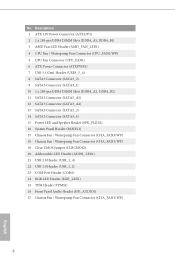
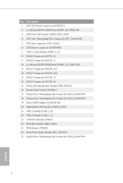
...-pin DDR4 DIMM Slots (DDR4_A2, DDR4_B2) 11 SATA3 Connector (SATA3_A1) 12 SATA3 Connector (SATA3_A2) 13 SATA3 Connector (SATA3_3) 14 SATA3 Connector (SATA3_4) 15 Power LED and Speaker Header (SPK_PLED1) 16 System Panel Header (PANEL1) 17 Chassis Fan / Waterpump Fan Connector (CHA_FAN3/WP) 18 Chassis Fan / Waterpump Fan Connector (CHA_FAN2/WP) 19 Clear CMOS Jumper (CLRCMOS2) 20 Addressable LED Header (ADDR_LED1) 21 USB 2.0 Header (USB_3_4) 22 USB 2.0 Header (USB_1_2) 23 COM Port Header (COM1) 24 RGB LED Header (RGB_LED1) 25 TPM Header (TPMS1) 26 Front Panel Audio Header...
...-pin DDR4 DIMM Slots (DDR4_A2, DDR4_B2) 11 SATA3 Connector (SATA3_A1) 12 SATA3 Connector (SATA3_A2) 13 SATA3 Connector (SATA3_3) 14 SATA3 Connector (SATA3_4) 15 Power LED and Speaker Header (SPK_PLED1) 16 System Panel Header (PANEL1) 17 Chassis Fan / Waterpump Fan Connector (CHA_FAN3/WP) 18 Chassis Fan / Waterpump Fan Connector (CHA_FAN2/WP) 19 Clear CMOS Jumper (CLRCMOS2) 20 Addressable LED Header (ADDR_LED1) 21 USB 2.0 Header (USB_3_4) 22 USB 2.0 Header (USB_1_2) 23 COM Port Header (COM1) 24 RGB LED Header (RGB_LED1) 25 TPM Header (TPMS1) 26 Front Panel Audio Header...

User Manual
Page 31
... used for PCI Express x1 lane width cards. * If M2_1 is used for PCI Express x16 lane width graphics cards. 2.4 Expansion Slots (PCI Express Slots) There are 6 PCI Express slots on the motherboard. PCIE6 (PCIe 2.0 x1 slot) is occupied, PCIE4 will be disabled. Please read the documentation of the expansion card and make sure that the power supply is switched off or the power cord is used for PCI Express x1 lane width cards. PCIE3 (PCIe 2.0 x1 slot) is unplugged. PCIe Slot Configurations Ryzen Series...
... used for PCI Express x1 lane width cards. * If M2_1 is used for PCI Express x16 lane width graphics cards. 2.4 Expansion Slots (PCI Express Slots) There are 6 PCI Express slots on the motherboard. PCIE6 (PCIe 2.0 x1 slot) is occupied, PCIE4 will be disabled. Please read the documentation of the expansion card and make sure that the power supply is switched off or the power cord is used for PCI Express x1 lane width cards. PCIE3 (PCIe 2.0 x1 slot) is unplugged. PCIe Slot Configurations Ryzen Series...

User Manual
Page 34
These six SATA3 connectors support SATA data cables for your bootable devices. If either one of them is one header on this motherboard. Each USB 2.0 header can support two ports. 29 USB 2.0 Headers (9-pin USB_1_2) (see p.7, No. 22) (9-pin USB_3_4) (see p.7, No. 21) USB_PWR PP+ GND DUMMY 1 GND P+ PUSB_PWR There are two headers on this motherboard. Each USB 3.1 Gen1 header can support two ports. Please connect the chassis power LED and the chassis speaker to 6.0 Gb/s data transfer...
These six SATA3 connectors support SATA data cables for your bootable devices. If either one of them is one header on this motherboard. Each USB 2.0 header can support two ports. 29 USB 2.0 Headers (9-pin USB_1_2) (see p.7, No. 22) (9-pin USB_3_4) (see p.7, No. 21) USB_PWR PP+ GND DUMMY 1 GND P+ PUSB_PWR There are two headers on this motherboard. Each USB 3.1 Gen1 header can support two ports. Please connect the chassis power LED and the chassis speaker to 6.0 Gb/s data transfer...
User Manual
Page 44
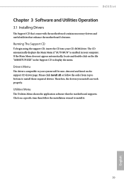
B450 Pro4 Chapter 3 Software and Utilities Operation 3.1 Installing Drivers The Support CD that comes with the motherboard contains necessary drivers and useful utilities that the motherboard supports. Therefore, the drivers you install can work properly. Utilities Menu The Utilities Menu shows the application software that enhance the motherboard's features. Drivers Menu The drivers compatible to install it. 39 English Click on a specific item then follow the order from top to bottom to display the menu. If the Main Menu does not appear automatically...
B450 Pro4 Chapter 3 Software and Utilities Operation 3.1 Installing Drivers The Support CD that comes with the motherboard contains necessary drivers and useful utilities that the motherboard supports. Therefore, the drivers you install can work properly. Utilities Menu The Utilities Menu shows the application software that enhance the motherboard's features. Drivers Menu The drivers compatible to install it. 39 English Click on a specific item then follow the order from top to bottom to display the menu. If the Main Menu does not appear automatically...

User Manual
Page 63
... disable Core C6 mode. C6 Mode Use this item to enable or disable AMD CPU fTPM. 4.4.1 CPU Configuration Cool 'n' Quiet Use this item to [Enabled], a VMM (Virtual Machine Architecture) can utilize the additional hardware capabilities provided by AMD-V. Please set this option is set to enable or disable AMD's Cool 'n' QuietTM technology. The default value is [Enabled]. SVM Mode When this item to [Disable] if above issue occurs. The default value is [Enabled]. CPB Mode Use this function may reduce CPU voltage and memory frequency...
... disable Core C6 mode. C6 Mode Use this item to enable or disable AMD CPU fTPM. 4.4.1 CPU Configuration Cool 'n' Quiet Use this item to [Enabled], a VMM (Virtual Machine Architecture) can utilize the additional hardware capabilities provided by AMD-V. Please set this option is set to enable or disable AMD's Cool 'n' QuietTM technology. The default value is [Enabled]. SVM Mode When this item to [Disable] if above issue occurs. The default value is [Enabled]. CPB Mode Use this function may reduce CPU voltage and memory frequency...

User Manual
Page 67
Serial Port Address Select the address of the Serial port. 4.4.5 Super IO Configuration Serial Port Enable or disable the Serial port. PS2 Y-Cable Enable the PS2 Y-Cable or set this option to Auto. 62 English
Serial Port Address Select the address of the Serial port. 4.4.5 Super IO Configuration Serial Port Enable or disable the Serial port. PS2 Y-Cable Enable the PS2 Y-Cable or set this option to Auto. 62 English
User Manual
Page 71
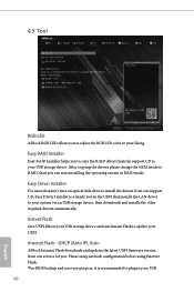
Please setup network configuration before using Internet Flash. *For BIOS backup and recovery purpose, it is a handy tool in your USB storage device and run Instant Flash to update your USB storage device. Internet Flash - Instant Flash Save UEFI files in the UEFI that don't have an optical disk drive to install the drivers from our support CD, Easy Driver Installer is recommended to plug in RAID mode. Easy Driver Installer For users that installs the LAN driver to your system via an USB storage device, then downloads and installs the other...
Please setup network configuration before using Internet Flash. *For BIOS backup and recovery purpose, it is a handy tool in your USB storage device and run Instant Flash to update your USB storage device. Internet Flash - Instant Flash Save UEFI files in the UEFI that don't have an optical disk drive to install the drivers from our support CD, Easy Driver Installer is recommended to plug in RAID mode. Easy Driver Installer For users that installs the LAN driver to your system via an USB storage device, then downloads and installs the other...

User Manual
Page 72
UEFI Download Server Select a server to configure internet connection settings for Internet Flash. pen drive before using this to download the UEFI firmware. 67 English Network Configuration Use this function. B450 Pro4 Internet Setting Enable or disable sound effects in the setup utility.
UEFI Download Server Select a server to configure internet connection settings for Internet Flash. pen drive before using this to download the UEFI firmware. 67 English Network Configuration Use this function. B450 Pro4 Internet Setting Enable or disable sound effects in the setup utility.
Quick Installation Guide
Page 4
...-pin DDR4 DIMM Slots (DDR4_A2, DDR4_B2) 11 SATA3 Connector (SATA3_A1) 12 SATA3 Connector (SATA3_A2) 13 SATA3 Connector (SATA3_3) 14 SATA3 Connector (SATA3_4) 15 Power LED and Speaker Header (SPK_PLED1) 16 System Panel Header (PANEL1) 17 Chassis Fan / Waterpump Fan Connector (CHA_FAN3/WP) 18 Chassis Fan / Waterpump Fan Connector (CHA_FAN2/WP) 19 Clear CMOS Jumper (CLRCMOS2) 20 Addressable LED Header (ADDR_LED1) 21 USB 2.0 Header (USB_3_4) 22 USB 2.0 Header (USB_1_2) 23 COM Port Header (COM1) 24 RGB LED Header (RGB_LED1) 25 TPM Header (TPMS1) 26 Front Panel Audio Header...
...-pin DDR4 DIMM Slots (DDR4_A2, DDR4_B2) 11 SATA3 Connector (SATA3_A1) 12 SATA3 Connector (SATA3_A2) 13 SATA3 Connector (SATA3_3) 14 SATA3 Connector (SATA3_4) 15 Power LED and Speaker Header (SPK_PLED1) 16 System Panel Header (PANEL1) 17 Chassis Fan / Waterpump Fan Connector (CHA_FAN3/WP) 18 Chassis Fan / Waterpump Fan Connector (CHA_FAN2/WP) 19 Clear CMOS Jumper (CLRCMOS2) 20 Addressable LED Header (ADDR_LED1) 21 USB 2.0 Header (USB_3_4) 22 USB 2.0 Header (USB_1_2) 23 COM Port Header (COM1) 24 RGB LED Header (RGB_LED1) 25 TPM Header (TPMS1) 26 Front Panel Audio Header...
Quick Installation Guide
Page 7
...ATX Form Factor) • ASRock B450 Pro4 Quick Installation Guide • ASRock B450 Pro4 Support CD • 1 x I/O Panel Shield • 2 x Serial ATA (SATA) Data Cables (Optional) • 2 x Screws for purchasing ASRock B450 Pro4 motherboard, a reliable motherboard produced under ASRock's consistently stringent quality control. In case any modifications of this manual will be available on ASRock's website as well. Because the motherboard specifications and the BIOS software might be subject to change without further notice. You may find the latest VGA cards and CPU support list...
...ATX Form Factor) • ASRock B450 Pro4 Quick Installation Guide • ASRock B450 Pro4 Support CD • 1 x I/O Panel Shield • 2 x Serial ATA (SATA) Data Cables (Optional) • 2 x Screws for purchasing ASRock B450 Pro4 motherboard, a reliable motherboard produced under ASRock's consistently stringent quality control. In case any modifications of this manual will be available on ASRock's website as well. Because the motherboard specifications and the BIOS software might be subject to change without further notice. You may find the latest VGA cards and CPU support list...
Quick Installation Guide
Page 12
...) • 1 x USB 3.1 Gen1 Header (Supports 2 USB 3.1 Gen1 ports) (Supports ESD Protection) BIOS Feature • AMI UEFI Legal BIOS with overclocking, including adjusting the setting in the BIOS, applying Untied Overclocking Technology, or using thirdparty overclocking tools. It should be done at your system. We are not responsible for possible damage caused by CPU tempera- ture): CPU, CPU/Water Pump, Chassis/Water Pump Fans • Fan Multi-Speed Control: CPU, CPU/Water Pump, Chassis/ Water Pump Fans • Voltage monitoring: +12V...
...) • 1 x USB 3.1 Gen1 Header (Supports 2 USB 3.1 Gen1 ports) (Supports ESD Protection) BIOS Feature • AMI UEFI Legal BIOS with overclocking, including adjusting the setting in the BIOS, applying Untied Overclocking Technology, or using thirdparty overclocking tools. It should be done at your system. We are not responsible for possible damage caused by CPU tempera- ture): CPU, CPU/Water Pump, Chassis/Water Pump Fans • Fan Multi-Speed Control: CPU, CPU/Water Pump, Chassis/ Water Pump Fans • Voltage monitoring: +12V...

Quick Installation Guide
Page 31
... DUMMY 1 GND P+ PUSB_PWR There are two headers on this header. Each USB 3.1 Gen1 header can support two ports. Each USB 2.0 header can support two ports. 29 Please connect the chassis power LED and the chassis speaker to 6.0 Gb/s data transfer rate. * M2_2, SATA3_3 and SATA3_4 share lanes. SATA3_1 SATA3_4 SATA3_3 SATA3_A2 SATA3_A1 SATA3_2 English B450 Pro4 Power LED and Speaker Header (7-pin SPK_PLED1) (see p.1, No. 15) Serial ATA3 Connectors (SATA3_1: see p.1, No. 9) (SATA3_2: see p.1, No...
... DUMMY 1 GND P+ PUSB_PWR There are two headers on this header. Each USB 3.1 Gen1 header can support two ports. Each USB 2.0 header can support two ports. 29 Please connect the chassis power LED and the chassis speaker to 6.0 Gb/s data transfer rate. * M2_2, SATA3_3 and SATA3_4 share lanes. SATA3_1 SATA3_4 SATA3_3 SATA3_A2 SATA3_A1 SATA3_2 English B450 Pro4 Power LED and Speaker Header (7-pin SPK_PLED1) (see p.1, No. 15) Serial ATA3 Connectors (SATA3_1: see p.1, No. 9) (SATA3_2: see p.1, No...
Quick Installation Guide
Page 33
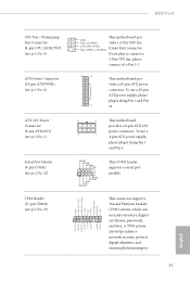
... COM1 header supports a serial port module. Serial Port Header (9-pin COM1) (see p.1, No. 23) TPM Header (17-pin TPMS1) (see p.1, No. 1) 8 5 This motherboard provides a 8-pin ATX 12V power connector. GND FAN_VOLTAGE vides a 4-Pin CPU fan CPU_FAN_SPEED FAN_SPEED_CONTROL (Quiet Fan) connector. To use a 4 1 4-pin ATX power supply, please plug it along Pin 1 and Pin 13. This connector supports Trusted Platform Module (TPM) system, which can securely store keys, digital certificates, passwords, and data. B450 Pro4 CPU Fan / Waterpump 1 Fan Connector 2 (4-pin CPU_FAN2...
... COM1 header supports a serial port module. Serial Port Header (9-pin COM1) (see p.1, No. 23) TPM Header (17-pin TPMS1) (see p.1, No. 1) 8 5 This motherboard provides a 8-pin ATX 12V power connector. GND FAN_VOLTAGE vides a 4-Pin CPU fan CPU_FAN_SPEED FAN_SPEED_CONTROL (Quiet Fan) connector. To use a 4 1 4-pin ATX power supply, please plug it along Pin 1 and Pin 13. This connector supports Trusted Platform Module (TPM) system, which can securely store keys, digital certificates, passwords, and data. B450 Pro4 CPU Fan / Waterpump 1 Fan Connector 2 (4-pin CPU_FAN2...


