

User Manual
Page 4
... 2 1.3 Motherboard Layout 6 1.4 I/O Panel 8 Chapter 2 Installation 10 2.1 Installing the CPU 11 2.2 Installing the CPU Fan and Heatsink 14 2.3 Installing Memory Modules (DIMM) 15 2.4 Expansion Slots (PCI Express Slots) 17 2.5 Jumpers Setup 18 2.6 Onboard Headers and Connectors 19 Chapter 3 Software and Utilities Operation 23 3.1 Installing Drivers 23 3.2 ASRock Live Update & APP Shop 24 3.2.1 UI Overview 24 3.2.2 Apps 25 3.2.3 BIOS & Drivers 28 3.2.4 Setting 29 3.3 Enabling USB Ports for Windows® 7 Installation 30 Chapter 4 UEFI SETUP UTILITY 33...
... 2 1.3 Motherboard Layout 6 1.4 I/O Panel 8 Chapter 2 Installation 10 2.1 Installing the CPU 11 2.2 Installing the CPU Fan and Heatsink 14 2.3 Installing Memory Modules (DIMM) 15 2.4 Expansion Slots (PCI Express Slots) 17 2.5 Jumpers Setup 18 2.6 Onboard Headers and Connectors 19 Chapter 3 Software and Utilities Operation 23 3.1 Installing Drivers 23 3.2 ASRock Live Update & APP Shop 24 3.2.1 UI Overview 24 3.2.2 Apps 25 3.2.3 BIOS & Drivers 28 3.2.4 Setting 29 3.3 Enabling USB Ports for Windows® 7 Installation 30 Chapter 4 UEFI SETUP UTILITY 33...
User Manual
Page 6
...; ASRock B150M-ITX/D3 Quick Installation Guide • ASRock B150M-ITX/D3 Support CD • 2 x Serial ATA (SATA) Data Cables (Optional) • 1 x I/O Panel Shield • 1 x WiFi Module Bracket • 2 x Screws for purchasing ASRock B150M-ITX/D3 motherboard, a reliable motherboard produced under ASRock's consistently stringent quality control. B150M-ITX/D3 Chapter 1 Introduction hank you are using. In this documentation, Chapter 1 and 2 contains the introduction of this motherboard, please visit our website for speciic information about the model...
...; ASRock B150M-ITX/D3 Quick Installation Guide • ASRock B150M-ITX/D3 Support CD • 2 x Serial ATA (SATA) Data Cables (Optional) • 1 x I/O Panel Shield • 1 x WiFi Module Bracket • 2 x Screws for purchasing ASRock B150M-ITX/D3 motherboard, a reliable motherboard produced under ASRock's consistently stringent quality control. B150M-ITX/D3 Chapter 1 Introduction hank you are using. In this documentation, Chapter 1 and 2 contains the introduction of this motherboard, please visit our website for speciic information about the model...
User Manual
Page 8
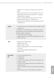
...; Supports Lightning/ESD Protection (ASRock Full Spike Protection) • Supports Energy Eicient Ethernet 802.3az • Supports PXE Rear Panel I/O • 1 x PS/2 Mouse/Keyboard Port • 1 x DVI-D Port • 1 x HDMI Port • 2 x USB 2.0 Ports (Supports ESD Protection (ASRock Full Spike Protection)) • 4 x USB 3.0 Ports (Supports ESD Protection (ASRock Full Spike Protection)) • 1 x RJ-45 LAN Port with max. B150M-ITX/D3 • Supports DVI-D with LED (ACT/LINK LED and SPEED LED) • HD Audio Jacks: Line in / Front Speaker...
...; Supports Lightning/ESD Protection (ASRock Full Spike Protection) • Supports Energy Eicient Ethernet 802.3az • Supports PXE Rear Panel I/O • 1 x PS/2 Mouse/Keyboard Port • 1 x DVI-D Port • 1 x HDMI Port • 2 x USB 2.0 Ports (Supports ESD Protection (ASRock Full Spike Protection)) • 4 x USB 3.0 Ports (Supports ESD Protection (ASRock Full Spike Protection)) • 1 x RJ-45 LAN Port with max. B150M-ITX/D3 • Supports DVI-D with LED (ACT/LINK LED and SPEED LED) • HD Audio Jacks: Line in / Front Speaker...

User Manual
Page 9
... multi-speed control • CASE OPEN detection • Voltage monitoring: +12V, +5V, +3.3V, CPU Vcore English OS 4 • Microsot® Windows® 10 64-bit / 8.1 64-bit / 7 32-bit / 7 64bit * To install Windows® 7 OS, a modiied installation disk with multilingual GUI sup- Storage • 5 x SATA3 6.0 Gb/s Connectors, support NCQ, AHCI and Hot Plug • 1 x mSATA Connector (shared with Mini-PCI Express Slot), support NCQ, AHCI and Hot Plug Connector • 1 x TPM Header • 1 x Chassis Intrusion Header • 1 x CPU Fan Connector (4-pin) (Smart Fan Speed Control...
... multi-speed control • CASE OPEN detection • Voltage monitoring: +12V, +5V, +3.3V, CPU Vcore English OS 4 • Microsot® Windows® 10 64-bit / 8.1 64-bit / 7 32-bit / 7 64bit * To install Windows® 7 OS, a modiied installation disk with multilingual GUI sup- Storage • 5 x SATA3 6.0 Gb/s Connectors, support NCQ, AHCI and Hot Plug • 1 x mSATA Connector (shared with Mini-PCI Express Slot), support NCQ, AHCI and Hot Plug Connector • 1 x TPM Header • 1 x Chassis Intrusion Header • 1 x CPU Fan Connector (4-pin) (Smart Fan Speed Control...

User Manual
Page 20
... permanent damage to the motherboard and the DIMM if you always need to install a DDR or DDR2 memory module into the slot at incorrect orientation. 15 English B150M-ITX/D3 2.3 Installing Memory Modules (DIMM) his motherboard provides two 240-pin DDR3/DDR3L (Double Data Rate 3) DIMM slots, and supports Dual Channel Memory Technology. 1. It is not allowed to install identical (the same brand, speed, size and chip-type) DDR3/DDR3L DIMM...
... permanent damage to the motherboard and the DIMM if you always need to install a DDR or DDR2 memory module into the slot at incorrect orientation. 15 English B150M-ITX/D3 2.3 Installing Memory Modules (DIMM) his motherboard provides two 240-pin DDR3/DDR3L (Double Data Rate 3) DIMM slots, and supports Dual Channel Memory Technology. 1. It is not allowed to install identical (the same brand, speed, size and chip-type) DDR3/DDR3L DIMM...

User Manual
Page 22
PCIe slot: PCIE1 (PCIe 3.0 x16 slot) is used for WiFi and mSATA devices. 17 English mini-PCIe slot: MPCIE1 (mini-PCIe slot) is used for PCI Express x16 lane width graphics cards. B150M-ITX/D3 2.4 Expansion Slots (PCI Express Slots) here is unplugged. Please read the documentation of the expansion card and make sure that the power supply is switched of or the power cord is 1 PCI Express slot and 1 mini-PCI Express slot on the motherboard. Before installing an expansion card, please make necessary hardware settings for the card before you start the installation.
PCIe slot: PCIE1 (PCIe 3.0 x16 slot) is used for WiFi and mSATA devices. 17 English mini-PCIe slot: MPCIE1 (mini-PCIe slot) is used for PCI Express x16 lane width graphics cards. B150M-ITX/D3 2.4 Expansion Slots (PCI Express Slots) here is unplugged. Please read the documentation of the expansion card and make sure that the power supply is switched of or the power cord is 1 PCI Express slot and 1 mini-PCI Express slot on the motherboard. Before installing an expansion card, please make necessary hardware settings for the card before you start the installation.

User Manual
Page 23
... update the BIOS. 2.5 Jumpers Setup he illustration shows a 3-pin jumper whose pin1 and pin2 are setup. If you need to short pin2 and pin3 on these 2 pins. If you to default setup, please turn of previous chassis intrusion status. When the jumper cap is placed on the pins, the jumper is "Short". Clear CMOS Jumper (CLRMOS1) (see p.6, No. 11) Default Clear CMOS CLRMOS1 allows you clear the CMOS, the case open may be cleared only if the CMOS battery...
... update the BIOS. 2.5 Jumpers Setup he illustration shows a 3-pin jumper whose pin1 and pin2 are setup. If you need to short pin2 and pin3 on these 2 pins. If you to default setup, please turn of previous chassis intrusion status. When the jumper cap is placed on the pins, the jumper is "Short". Clear CMOS Jumper (CLRMOS1) (see p.6, No. 11) Default Clear CMOS CLRMOS1 allows you clear the CMOS, the case open may be cleared only if the CMOS battery...

User Manual
Page 24
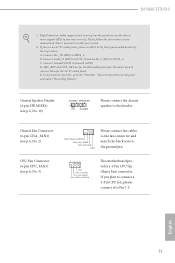
... by chassis. RESET (Reset Switch): Connect to turn of power switch, reset switch, power LED, hard drive activity LED, speaker and etc. A front panel module mainly consists of your chassis front panel module to this header according to the motherboard. System Panel Header (9-pin PANEL1) (see p.6, No. 9) GND PWRBTN# PLEDPLED+ GND RESET# GND HDLEDHDLED+ 1 Connect the power switch, reset switch and system status indicator on the chassis front panel. he LED is on the chassis front panel. B150M-ITX/D3 2.6 Onboard Headers and Connectors Onboard headers and connectors are...
... by chassis. RESET (Reset Switch): Connect to turn of power switch, reset switch, power LED, hard drive activity LED, speaker and etc. A front panel module mainly consists of your chassis front panel module to this header according to the motherboard. System Panel Header (9-pin PANEL1) (see p.6, No. 9) GND PWRBTN# PLEDPLED+ GND RESET# GND HDLEDHDLED+ 1 Connect the power switch, reset switch and system status indicator on the chassis front panel. he LED is on the chassis front panel. B150M-ITX/D3 2.6 Onboard Headers and Connectors Onboard headers and connectors are...
User Manual
Page 26
... wire to Pin 1-3. CPU Fan Connector (4-pin CPU_FAN1) (see p.6, No. 3) 4 3 21 GND FAN_VOLTAGE CPU_FAN_SPEED FAN_SPEED_CONTROL his motherboard provides a 4-Pin CPU fan (Quiet Fan) connector. B150M-ITX/D3 1. B. Please follow the instructions in the Realtek Control panel and adjust "Recording Volume". D. To activate the front mic, go to function correctly. If you use an AC'97 audio panel, please install it to the ground pin. High Deinition Audio supports Jack Sensing, but the panel wire on the chassis must support...
... wire to Pin 1-3. CPU Fan Connector (4-pin CPU_FAN1) (see p.6, No. 3) 4 3 21 GND FAN_VOLTAGE CPU_FAN_SPEED FAN_SPEED_CONTROL his motherboard provides a 4-Pin CPU fan (Quiet Fan) connector. B150M-ITX/D3 1. B. Please follow the instructions in the Realtek Control panel and adjust "Recording Volume". D. To activate the front mic, go to function correctly. If you use an AC'97 audio panel, please install it to the ground pin. High Deinition Audio supports Jack Sensing, but the panel wire on the chassis must support...
User Manual
Page 28
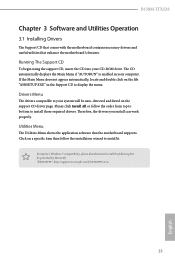
..., the drivers you install can work properly. Utilities Menu he Support CD that comes with the motherboard contains necessary drivers and useful utilities that the motherboard supports. Click on the support CD driver page. B150M-ITX/D3 Chapter 3 Software and Utilities Operation 3.1 Installing Drivers he Utilities Menu shows the application sotware that enhance the motherboard's features. Drivers Menu he CD automatically displays the Main Menu if "AUTORUN" is enabled in the Support CD to display the menu. To improve Windows 7 compatibility, please download and install the...
..., the drivers you install can work properly. Utilities Menu he Support CD that comes with the motherboard contains necessary drivers and useful utilities that the motherboard supports. Click on the support CD driver page. B150M-ITX/D3 Chapter 3 Software and Utilities Operation 3.1 Installing Drivers he Utilities Menu shows the application sotware that enhance the motherboard's features. Drivers Menu he CD automatically displays the Main Menu if "AUTORUN" is enabled in the Support CD to display the menu. To improve Windows 7 compatibility, please download and install the...

User Manual
Page 35
... an optical disc drive, PS/2 ports and PS/2 Keyboard or mouse on their support for the USB ports to disabled ater the installation. USB2.0) and only kept the eXtensible Host Controller Interface (XHCI - Requirements • A Windows® 7 installation disk or USB drive • USB 3.0 drivers (included in the ASRock Support CD or website) • A Windows® PC • Win7 USB Patcher (included in UEFI SETUP UTILITY > Advanced > USB Coniguration, which allows the USB port to create...
... an optical disc drive, PS/2 ports and PS/2 Keyboard or mouse on their support for the USB ports to disabled ater the installation. USB2.0) and only kept the eXtensible Host Controller Interface (XHCI - Requirements • A Windows® 7 installation disk or USB drive • USB 3.0 drivers (included in the ASRock Support CD or website) • A Windows® PC • Win7 USB Patcher (included in UEFI SETUP UTILITY > Advanced > USB Coniguration, which allows the USB port to create...
User Manual
Page 36
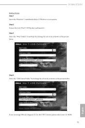
Step 4 Select the "USB Driver Folder" by clicking the red circle as shown as the picture below . Step 3 Select the "Win7 Folder" from Step1 by clicking the red circle as shown as the picture below . B150M-ITX/D3 Instructions Step 1 Insert the Windows® 7 installation disk or USB drive to your CD-ROM. 31 English If you are using ASRock's Support CD for the USB 3.0 driver, please select your system. Step 2 Extract the tool (Win7 USB Patcher) and launch it.
Step 4 Select the "USB Driver Folder" by clicking the red circle as shown as the picture below . Step 3 Select the "Win7 Folder" from Step1 by clicking the red circle as shown as the picture below . B150M-ITX/D3 Instructions Step 1 Insert the Windows® 7 installation disk or USB drive to your CD-ROM. 31 English If you are using ASRock's Support CD for the USB 3.0 driver, please select your system. Step 2 Extract the tool (Win7 USB Patcher) and launch it.
User Manual
Page 38
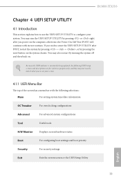
... they may run the UEFI SETUP UTILITY by turning the system of the screen has a menu bar with its test routines. Because the UEFI sotware is constantly being updated, the following selections: Main For setting system time/date information OC Tweaker For overclocking conigurations Advanced For advanced system conigurations Tool Useful tools H/W Monitor Displays current hardware status Boot For coniguring boot settings and boot priority Security For security...
... they may run the UEFI SETUP UTILITY by turning the system of the screen has a menu bar with its test routines. Because the UEFI sotware is constantly being updated, the following selections: Main For setting system time/date information OC Tweaker For overclocking conigurations Advanced For advanced system conigurations Tool Useful tools H/W Monitor Displays current hardware status Boot For coniguring boot settings and boot priority Security For security...

User Manual
Page 53
PCH PCIE ASPM Support his option enables/disables the ASPM support for all PCH PCIE devices. DMI ASPM Support his option enables/disables the ASPM support for all CPU downstream devices. 4.4.2 Chipset Coniguration Primary Graphics Adapter Select a primary VGA. PCIE1 Link Speed Select the link speed for Directed I /O performance. VT-d Intel® Virtualization Technology for PCIE1. PCIE ASPM Support his option enables/disables the control of ASPM on CPU side of manageability, security, isolation, and I /O helps your virtual machine monitor better utilize hardware...
PCH PCIE ASPM Support his option enables/disables the ASPM support for all PCH PCIE devices. DMI ASPM Support his option enables/disables the ASPM support for all CPU downstream devices. 4.4.2 Chipset Coniguration Primary Graphics Adapter Select a primary VGA. PCIE1 Link Speed Select the link speed for Directed I /O performance. VT-d Intel® Virtualization Technology for PCIE1. PCIE ASPM Support his option enables/disables the control of ASPM on CPU side of manageability, security, isolation, and I /O helps your virtual machine monitor better utilize hardware...
User Manual
Page 54
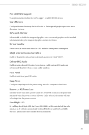
... be switched of the Power and Keyboard LEDs when the system enters into Standby/Hibernation mode. 49 English Good Night LED By enabling Good Night LED, the Power/HDD LEDs will start to enable onboard HD audio and automatically disable it when a sound card is idle for power saving when the computer is installed. It will remain of memory that is on AC/Power Loss Select the power state ater a power failure. Onboard HD Audio Enable/disable onboard HD audio. Set to Auto to boot...
... be switched of the Power and Keyboard LEDs when the system enters into Standby/Hibernation mode. 49 English Good Night LED By enabling Good Night LED, the Power/HDD LEDs will start to enable onboard HD audio and automatically disable it when a sound card is idle for power saving when the computer is installed. It will remain of memory that is on AC/Power Loss Select the power state ater a power failure. Onboard HD Audio Enable/disable onboard HD audio. Set to Auto to boot...

User Manual
Page 58
his should be enabled for the complete USB keyboard legacy support for USB 2.0 devices. Port 60/64 Emulation Enable the support of I/O port 60h/64h emulation. If you install Windows 7. 53 English Select UEFI Setup Only to disable legacy USB support. 4.4.6 USB Coniguration B150M-ITX/D3 Legacy USB Support Enable or disable Legacy OS Support for non-USB aware OS. *Enable this option if you encounter USB compatibility issues it is recommended to support USB devices under the UEFI setup and Windows/Linux operating systems only.
his should be enabled for the complete USB keyboard legacy support for USB 2.0 devices. Port 60/64 Emulation Enable the support of I/O port 60h/64h emulation. If you install Windows 7. 53 English Select UEFI Setup Only to disable legacy USB support. 4.4.6 USB Coniguration B150M-ITX/D3 Legacy USB Support Enable or disable Legacy OS Support for non-USB aware OS. *Enable this option if you encounter USB compatibility issues it is recommended to support USB devices under the UEFI setup and Windows/Linux operating systems only.
User Manual
Page 60
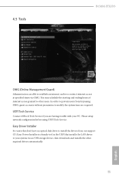
.... UEFI Tech Service Contact ASRock Tech Service if you are required. Please setup network coniguration before using UEFI Tech Service. You may schedule the starting and ending hours of internet access granted to establish an internet curfew or restrict internet access at speciied times via an USB storage device, then downloads and installs the other users. 4.5 Tools B150M-ITX/D3 OMG (Online Management Guard) Administrators are able to other required drivers...
.... UEFI Tech Service Contact ASRock Tech Service if you are required. Please setup network coniguration before using UEFI Tech Service. You may schedule the starting and ending hours of internet access granted to establish an internet curfew or restrict internet access at speciied times via an USB storage device, then downloads and installs the other users. 4.5 Tools B150M-ITX/D3 OMG (Online Management Guard) Administrators are able to other required drivers...
User Manual
Page 62
B150M-ITX/D3 Dehumidiier Duration Conigure the duration of the CPU fan while Dehumidiier is recommended to plug in your USB storage device and run Instant Flash to update your USB pen drive before using this function. 57 English DHCP (Auto IP), Auto ASRock Internet Flash downloads and updates the latest UEFI irmware version from our servers for you. Dehumidiier CPU Fan Setting Conigure the speed of the dehumidifying process before it is enabled. Max: 255 Min: 1 Instant...
B150M-ITX/D3 Dehumidiier Duration Conigure the duration of the CPU fan while Dehumidiier is recommended to plug in your USB storage device and run Instant Flash to update your USB pen drive before using this function. 57 English DHCP (Auto IP), Auto ASRock Internet Flash downloads and updates the latest UEFI irmware version from our servers for you. Dehumidiier CPU Fan Setting Conigure the speed of the dehumidifying process before it is enabled. Max: 255 Min: 1 Instant...

User Manual
Page 63
Internet Setting Enable or disable sound efects in the setup utility. UEFI Download Server Select a server to conigure internet connection settings for Internet Flash. Network Coniguration Use this to download the UEFI irmware. 58 English
Internet Setting Enable or disable sound efects in the setup utility. UEFI Download Server Select a server to conigure internet connection settings for Internet Flash. Network Coniguration Use this to download the UEFI irmware. 58 English
User Manual
Page 66
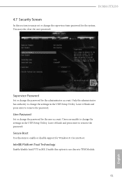
... press enter to remove the password. Intel(R) Platform Trust Technology Enable/disable Intel PTT in the UEFI Setup Utility. You may set or change the supervisor/user password for the system. B150M-ITX/D3 4.7 Security Screen In this item to enable or disable support for Windows 8.1 Secure Boot. User Password Set or change the settings in the UEFI Setup Utility. Users are unable to use discrete TPM Module. 61 English Disable this option to change the password for the administrator account. Supervisor Password Set or change the settings in...
... press enter to remove the password. Intel(R) Platform Trust Technology Enable/disable Intel PTT in the UEFI Setup Utility. You may set or change the supervisor/user password for the system. B150M-ITX/D3 4.7 Security Screen In this item to enable or disable support for Windows 8.1 Secure Boot. User Password Set or change the settings in the UEFI Setup Utility. Users are unable to use discrete TPM Module. 61 English Disable this option to change the password for the administrator account. Supervisor Password Set or change the settings in...


