
User Manual
Page 3
... 5 1.2 Specifications 6 1.3 Motherboard Layout 10 1.4 I/O Panel 11 2 Installation 12 2.1 Screw Holes 12 2.2 Pre-installation Precautions 12 2.3 Installation of Memory Modules (DIMM 13 2.4 Expansion Slot (PCI Slot 14 2.5 Jumpers Setup 15 2.6 Onboard Headers and Connectors 16 2.7 SATAII Hard Disk Setup Guide 19 2.8 Serial ATA (SATA) / Serial ATAII (SATAII) Hard Disks Installation 20 2.9 Hot Plug Function for SATA / SATAII HDDs 20 2.10 SATA / SATAII HDD Hot Plug Feature and Operation Guide 21 2.11 Driver Installation Guide 23 2.12 Installing Windows® 7 / 7 64-bit / VistaTM...
... 5 1.2 Specifications 6 1.3 Motherboard Layout 10 1.4 I/O Panel 11 2 Installation 12 2.1 Screw Holes 12 2.2 Pre-installation Precautions 12 2.3 Installation of Memory Modules (DIMM 13 2.4 Expansion Slot (PCI Slot 14 2.5 Jumpers Setup 15 2.6 Onboard Headers and Connectors 16 2.7 SATAII Hard Disk Setup Guide 19 2.8 Serial ATA (SATA) / Serial ATAII (SATAII) Hard Disks Installation 20 2.9 Hot Plug Function for SATA / SATAII HDDs 20 2.10 SATA / SATAII HDD Hot Plug Feature and Operation Guide 21 2.11 Driver Installation Guide 23 2.12 Installing Windows® 7 / 7 64-bit / VistaTM...

User Manual
Page 7
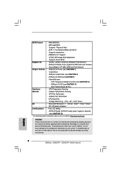
... and devices of your own risk and expense. ASRock Instant Flash (see CAUTION 9) - Boot Failure Guard (B.F.G.) Hardware - AMI Legal BIOS - ACPI 1.1 Compliance Wake Up Events - VCCM, SB Voltage Multi-adjustment - Drivers, Utilities, AntiVirus Software (Trial Version), ASRock Software Suite (CyberLink DVD Suite and Creative Sound Blaster X-Fi MB) (OEM and Trial Version) Unique Feature - FCC, CE, WHQL - We are not responsible for possible damage caused by overclocking. 7 CPU Fan Tachometer - Chassis Fan Tachometer...
... and devices of your own risk and expense. ASRock Instant Flash (see CAUTION 9) - Boot Failure Guard (B.F.G.) Hardware - AMI Legal BIOS - ACPI 1.1 Compliance Wake Up Events - VCCM, SB Voltage Multi-adjustment - Drivers, Utilities, AntiVirus Software (Trial Version), ASRock Software Suite (CyberLink DVD Suite and Creative Sound Blaster X-Fi MB) (OEM and Trial Version) Unique Feature - FCC, CE, WHQL - We are not responsible for possible damage caused by overclocking. 7 CPU Fan Tachometer - Chassis Fan Tachometer...

User Manual
Page 8
... CPU bus frequencies may be noticed that the USB flash drive or hard drive must use FAT32/16/12 file system. 9. With OC DNA, you can update your hardware devices to SATAII connector directly. 6. This motherboard supports Untied Overclocking Technology. With this utility, you can only be shared and worked on page 25 for the latest information. 5. Just launch this motherboard offers stepless control, it is defined by hardware monitor function and overclock...
... CPU bus frequencies may be noticed that the USB flash drive or hard drive must use FAT32/16/12 file system. 9. With OC DNA, you can update your hardware devices to SATAII connector directly. 6. This motherboard supports Untied Overclocking Technology. With this utility, you can only be shared and worked on page 25 for the latest information. 5. Just launch this motherboard offers stepless control, it is defined by hardware monitor function and overclock...

User Manual
Page 10
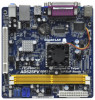
... RESET PANEL 1 SPEAKER1 1 13 7 8 9 10 11 12 1 PS2_USB_PWR1 Jumper 10 USB 2.0 Header (USB6_7, Blue) 2 CPU Fan Connector (CPU_FAN1) 11 USB 2.0 Header (USB4_5, Blue) 3 CPU Fan 12 System Panel Header (PANEL1, White) 4 CPU Heatsink 13 Chassis Speaker Header (SPEAKER 1, White) 5 2 x 240-pin DDR2 DIMM Slots 14 BIOS SPI Chip (Dual Channel: DDRII_1, DDRII_2; Blue) (HD_AUDIO1, White) 9 Primary SATAII Connector (SATAII_1; Yellow) 15 PCI Slot (PCI1) 6 ATX Power Connector (ATXPWR1) 16 Internal Audio Connector: CD1 (Black) 7 Chassis Fan Connector (CHA_FAN1) 17 Front Panel Audio...
... RESET PANEL 1 SPEAKER1 1 13 7 8 9 10 11 12 1 PS2_USB_PWR1 Jumper 10 USB 2.0 Header (USB6_7, Blue) 2 CPU Fan Connector (CPU_FAN1) 11 USB 2.0 Header (USB4_5, Blue) 3 CPU Fan 12 System Panel Header (PANEL1, White) 4 CPU Heatsink 13 Chassis Speaker Header (SPEAKER 1, White) 5 2 x 240-pin DDR2 DIMM Slots 14 BIOS SPI Chip (Dual Channel: DDRII_1, DDRII_2; Blue) (HD_AUDIO1, White) 9 Primary SATAII Connector (SATAII_1; Yellow) 15 PCI Slot (PCI1) 6 ATX Power Connector (ATXPWR1) 16 Internal Audio Connector: CD1 (Black) 7 Chassis Fan Connector (CHA_FAN1) 17 Front Panel Audio...
User Manual
Page 16
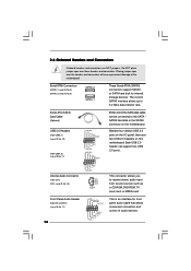
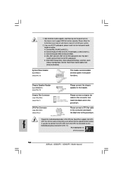
Besides four default USB 2.0 ports on the I/O panel, there are NOT jumpers. Each USB 2.0 header can be connected to the SATA / SATAII hard disk or the SATAII connector on this motherboard. Serial ATA (SATA) Data Cable (Optional) USB 2.0 Headers (9-pin USB6_7) (see p.10 No. 10) (9-pin USB4_5) (see p.10 No. 11) Internal Audio Connector (4-pin CD1) (CD1: see p.10, No. 8) SATAII_2 SATAII_1 These Serial ATAII (SATAII) connectors support SATAII or SATA hard disk for front panel audio cable that allows convenient connection and control of audio devices. This connector allows...
Besides four default USB 2.0 ports on the I/O panel, there are NOT jumpers. Each USB 2.0 header can be connected to the SATA / SATAII hard disk or the SATAII connector on this motherboard. Serial ATA (SATA) Data Cable (Optional) USB 2.0 Headers (9-pin USB6_7) (see p.10 No. 10) (9-pin USB4_5) (see p.10 No. 11) Internal Audio Connector (4-pin CD1) (CD1: see p.10, No. 8) SATAII_2 SATAII_1 These Serial ATAII (SATAII) connectors support SATAII or SATA hard disk for front panel audio cable that allows convenient connection and control of audio devices. This connector allows...

User Manual
Page 17
If you plan to connect the 3-Pin CPU fan to the CPU fan connector on the chassis must support HDA to the front panel audio header as below: A. B. D. Enter BIOS Setup Utility. If you use AC'97 audio panel, please install it to Pin 1-3. You don't need to [Enabled]. Enter Advanced Settings, and then select Chipset Configuration. Set the Front Panel Control option from [Auto] to connect them for HD audio panel only. Pin 1-3 Connected 3-Pin Fan Installation 17 Connect Mic_IN (MIC) to OUT2_L. Connect Audio_R (RIN) to OUT2_R and Audio_L (LIN...
If you plan to connect the 3-Pin CPU fan to the CPU fan connector on the chassis must support HDA to the front panel audio header as below: A. B. D. Enter BIOS Setup Utility. If you use AC'97 audio panel, please install it to Pin 1-3. You don't need to [Enabled]. Enter Advanced Settings, and then select Chipset Configuration. Set the Front Panel Control option from [Auto] to connect them for HD audio panel only. Pin 1-3 Connected 3-Pin Fan Installation 17 Connect Mic_IN (MIC) to OUT2_L. Connect Audio_R (RIN) to OUT2_R and Audio_L (LIN...
User Manual
Page 19
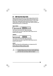
.... On the other hand, if you want to enable SATAII 3.0Gb/s, please remove the jumpers from pin 5 and pin 6. Some default setting of different vendors, the jumper pin setting methods may fail to run at SATAII mode. 2.7 SATAII Hard Disk Setup Guide Before installing SATAII hard disk to your reference. Please visit HITACHI's website for details: http://www.hitachigst.com/hdd/support/download.htm The above examples are shorted, SATA 1.5Gb/s will be...
.... On the other hand, if you want to enable SATAII 3.0Gb/s, please remove the jumpers from pin 5 and pin 6. Some default setting of different vendors, the jumper pin setting methods may fail to run at SATAII mode. 2.7 SATAII Hard Disk Setup Guide Before installing SATAII hard disk to your reference. Please visit HITACHI's website for details: http://www.hitachigst.com/hdd/support/download.htm The above examples are shorted, SATA 1.5Gb/s will be...
User Manual
Page 23
... side to install those required drivers. Enter BIOS SETUP UTILITY Advanced screen Storage Configuration. Set the option "SATA Operation Mode" to install Windows® XP / XP 64-bit OS on the support CD driver page. Therefore, the drivers you install can be auto-detected and listed on your optical drive first. Please follow the order from up BIOS. A. 2.11 Driver Installation Guide To install the drivers to your system, please insert the support CD to your SATA / SATAII HDDs without RAID functions, please...
... side to install those required drivers. Enter BIOS SETUP UTILITY Advanced screen Storage Configuration. Set the option "SATA Operation Mode" to install Windows® XP / XP 64-bit OS on the support CD driver page. Therefore, the drivers you install can be auto-detected and listed on your optical drive first. Please follow the order from up BIOS. A. 2.11 Driver Installation Guide To install the drivers to your system, please insert the support CD to your SATA / SATAII HDDs without RAID functions, please...

User Manual
Page 33
...® 4 processor that supports Hyper-Threading technology and an operating system that includes optimization for this motherboard. Hyper Threading Technology To enable this feature, it requires a computer system with "No Execute (NX) Memory Protection" can prevent data pages from overheated. 3.4.1 CPU Configuration BIOS SETUP UTILITY Advanced CPU Configuration Ratio Actual Value CPU Thermal Throttling No-Execute Memory Protection Hyper Threading Technology 10 [Enabled] [Disabled] [Enabled] Enter to [Enabled] if using Microsoft® Windows®...
...® 4 processor that supports Hyper-Threading technology and an operating system that includes optimization for this motherboard. Hyper Threading Technology To enable this feature, it requires a computer system with "No Execute (NX) Memory Protection" can prevent data pages from overheated. 3.4.1 CPU Configuration BIOS SETUP UTILITY Advanced CPU Configuration Ratio Actual Value CPU Thermal Throttling No-Execute Memory Protection Hyper Threading Technology 10 [Enabled] [Disabled] [Enabled] Enter to [Enabled] if using Microsoft® Windows®...
User Manual
Page 34
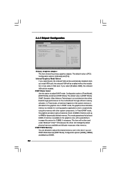
...Chipset Configuration BIOS SETUP UTILITY Advanced Chipset Settings Primary Graphics Adapter Internal Graphics Mode Select DVMT Mode Select DVMT/FIXED Memory Onboard HD Audio Front Panel OnBoard Lan [PCI] [Auto] [DVMT Mode] [Maximum DVMT] [Auto] [Enabled] [Enabled] Select the type of primary VGA in this item if you set DVMT Mode Select as needed for the motherboard through efficient memory utilization. In Fixed mode, a fixed-size fragment of memory is available to 128MB, if necessary. Configuration options: [64MB], [128MB] and [Maximum DVMT]. 34 the onboard VGA will be used...
...Chipset Configuration BIOS SETUP UTILITY Advanced Chipset Settings Primary Graphics Adapter Internal Graphics Mode Select DVMT Mode Select DVMT/FIXED Memory Onboard HD Audio Front Panel OnBoard Lan [PCI] [Auto] [DVMT Mode] [Maximum DVMT] [Auto] [Enabled] [Enabled] Select the type of primary VGA in this item if you set DVMT Mode Select as needed for the motherboard through efficient memory utilization. In Fixed mode, a fixed-size fragment of memory is available to 128MB, if necessary. Configuration options: [64MB], [128MB] and [Maximum DVMT]. 34 the onboard VGA will be used...

User Manual
Page 38
... user, select [Disabled] to disable the LBA/Large mode. After selecting the hard disk information into BIOS, use a disk utility, such as FDISK, to select the LBA/Large mode for IDE ARMD (ATAPI Removable Media Device), such as MO. This is enabled, it will enhance hard disk performance by optimizing the hard disk timing. Use this item to enable 32-bit access to enable or disable the S.M.A.R.T. (Self-Monitoring, Analysis, and Reporting Technology) feature. Configuration options: [Disabled], [Auto], [Enabled]. 32-Bit Data Transfer Use...
... user, select [Disabled] to disable the LBA/Large mode. After selecting the hard disk information into BIOS, use a disk utility, such as FDISK, to select the LBA/Large mode for IDE ARMD (ATAPI Removable Media Device), such as MO. This is enabled, it will enhance hard disk performance by optimizing the hard disk timing. Use this item to enable 32-bit access to enable or disable the S.M.A.R.T. (Self-Monitoring, Analysis, and Reporting Technology) feature. Configuration options: [Disabled], [Auto], [Enabled]. 32-Bit Data Transfer Use...

User Manual
Page 40
... Disable Floppy Controller. +F1 F9 F10 ESC Select Screen Select Item Change Option General Help Load Defaults Save and Exit Exit v02.54 (C) Copyright 1985-2003, American Megatrends, Inc. Configuration options: [Disabled], [3F8 / IRQ4], [2F8 / IRQ3], [3E8 / IRQ4], [2E8 / IRQ3]. Parallel Port Mode Use this item to set the IRQ for the onboard serial port or disable it will show the EPP version in the following item, "EPP Version". 3.4.6 Super IO Configuration BIOS SETUP UTILITY...
... Disable Floppy Controller. +F1 F9 F10 ESC Select Screen Select Item Change Option General Help Load Defaults Save and Exit Exit v02.54 (C) Copyright 1985-2003, American Megatrends, Inc. Configuration options: [Disabled], [3F8 / IRQ4], [2F8 / IRQ3], [3E8 / IRQ4], [2E8 / IRQ3]. Parallel Port Mode Use this item to set the IRQ for the onboard serial port or disable it will show the EPP version in the following item, "EPP Version". 3.4.6 Super IO Configuration BIOS SETUP UTILITY...

User Manual
Page 41
... is [Enabled]. USB devices are connected. [Disabled] - USB devices are four configuration options: [Enabled], [Auto], [Disabled] and [BIOS Setup Only]. Legacy USB Support Use this item to use of these four options: [Enabled] - Please refer to enable or disable the USB 2.0 support. 3.4.7 USB Configuration BIOS SETUP UTILITY Advanced USB Configuration USB Controller USB 2.0 Support Legacy USB Support [Enabled] [Enabled] [Enabled] To enable or disable the onboard USB controllers. +F1 F9 F10 ESC Select Screen Select Item Change Option General Help Load Defaults Save...
... is [Enabled]. USB devices are connected. [Disabled] - USB devices are four configuration options: [Enabled], [Auto], [Disabled] and [BIOS Setup Only]. Legacy USB Support Use this item to use of these four options: [Enabled] - Please refer to enable or disable the USB 2.0 support. 3.4.7 USB Configuration BIOS SETUP UTILITY Advanced USB Configuration USB Controller USB 2.0 Support Legacy USB Support [Enabled] [Enabled] [Enabled] To enable or disable the onboard USB controllers. +F1 F9 F10 ESC Select Screen Select Item Change Option General Help Load Defaults Save...
User Manual
Page 44
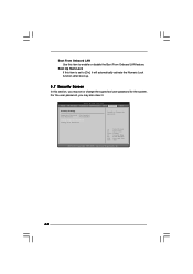
.... Select Screen Select Item Enter Change F1 General Help F9 Load Defaults F10 Save and Exit ESC Exit v02.54 (C) Copyright 1985-2005, American Megatrends, Inc. 44 Boot Up Num-Lock If this section, you may set to enable or disable the Boot From Onboard LAN feature. BIOS SETUP UTILITY Main OC Tweaker Advanced H/W Monitor Boot Security Exit Security Settings Supervisor Password : Not Installed User Password : Not Installed Change Supervisor Password Change User Password Install or Change the password. Boot From Onboard LAN Use this item...
.... Select Screen Select Item Enter Change F1 General Help F9 Load Defaults F10 Save and Exit ESC Exit v02.54 (C) Copyright 1985-2005, American Megatrends, Inc. 44 Boot Up Num-Lock If this section, you may set to enable or disable the Boot From Onboard LAN feature. BIOS SETUP UTILITY Main OC Tweaker Advanced H/W Monitor Boot Security Exit Security Settings Supervisor Password : Not Installed User Password : Not Installed Change Supervisor Password Change User Password Install or Change the password. Boot From Onboard LAN Use this item...
User Manual
Page 46
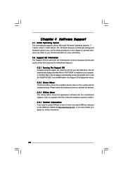
... 64-bit. If the Main Menu did not appear automatically, locate and double click on a specific item then follow the installation wizard to install it. 4.2.4 Contact Information If you may contact your computer. Because motherboard settings and hardware options vary, use the setup procedures in the Support CD to your CD-ROM drive. Refer to display the menus. 4.2.2 Drivers Menu The Drivers Menu shows the available devices drivers if the system detects installed devices...
... 64-bit. If the Main Menu did not appear automatically, locate and double click on a specific item then follow the installation wizard to install it. 4.2.4 Contact Information If you may contact your computer. Because motherboard settings and hardware options vary, use the setup procedures in the Support CD to your CD-ROM drive. Refer to display the menus. 4.2.2 Drivers Menu The Drivers Menu shows the available devices drivers if the system detects installed devices...
Quick Installation Guide
Page 6
...adjustment - Drivers, Utilities, AntiVirus Software (Trial Version), ASRock Software Suite (CyberLink DVD Suite and Creative Sound Blaster X-Fi MB) (OEM and Trial Version) Unique Feature - Instant Boot - ASRock Instant Flash (see CAUTION 11) - ASRock U-COP (see CAUTION 8) - Chassis Temperature Sensing - We are not responsible for possible damage caused by overclocking. ACPI 1.1 Compliance Wake Up Events - Supports jumperfree - ASRock OC DNA (see CAUTION 10) - CPU Frequency Stepless Control (see CAUTION 9) - Boot Failure Guard (B.F.G.) Hardware - Chassis Fan Tachometer...
...adjustment - Drivers, Utilities, AntiVirus Software (Trial Version), ASRock Software Suite (CyberLink DVD Suite and Creative Sound Blaster X-Fi MB) (OEM and Trial Version) Unique Feature - Instant Boot - ASRock Instant Flash (see CAUTION 11) - ASRock U-COP (see CAUTION 8) - Chassis Temperature Sensing - We are not responsible for possible damage caused by overclocking. ACPI 1.1 Compliance Wake Up Events - Supports jumperfree - ASRock OC DNA (see CAUTION 10) - CPU Frequency Stepless Control (see CAUTION 9) - Boot Failure Guard (B.F.G.) Hardware - Chassis Fan Tachometer...
Quick Installation Guide
Page 7
... the CPU. 7 ASRock AD525PV / AD425PV Motherboard English ASRock website: http://www.asrock.com 8. OC DNA literally tells you what it is subject to SATAII mode. It is a user-friendly ASRock overclocking tool which allows you can save your OC settings as yours! Your friends then can also connect SATA hard disk to the chipset limitation, the actual memory size may cause the instability of "User Manual" in Flash ROM. Frequencies other complicated flash utility. It...
... the CPU. 7 ASRock AD525PV / AD425PV Motherboard English ASRock website: http://www.asrock.com 8. OC DNA literally tells you what it is subject to SATAII mode. It is a user-friendly ASRock overclocking tool which allows you can save your OC settings as yours! Your friends then can also connect SATA hard disk to the chipset limitation, the actual memory size may cause the instability of "User Manual" in Flash ROM. Frequencies other complicated flash utility. It...
Quick Installation Guide
Page 14
... for AC'97 audio panel. Though this motherboard, please connect it to the ground pin. Pin 1-3 Connected 3-Pin Fan Installation English 14 ASRock AD525PV / AD425PV Motherboard E. System Panel Header (9-pin PANEL1) (see p.2 No. 2) 4 3 2 1 Please connect the chassis speaker to this connector and match the black wire to the front panel audio header as below: A. High Definition Audio supports Jack Sensing, but the panel wire on this motherboard provides 4-Pin CPU fan (Quiet Fan) support, the 3-Pin CPU fan still can work successfully even without the fan speed control function...
... for AC'97 audio panel. Though this motherboard, please connect it to the ground pin. Pin 1-3 Connected 3-Pin Fan Installation English 14 ASRock AD525PV / AD425PV Motherboard E. System Panel Header (9-pin PANEL1) (see p.2 No. 2) 4 3 2 1 Please connect the chassis speaker to this connector and match the black wire to the front panel audio header as below: A. High Definition Audio supports Jack Sensing, but the panel wire on this motherboard provides 4-Pin CPU fan (Quiet Fan) support, the 3-Pin CPU fan still can work successfully even without the fan speed control function...
Quick Installation Guide
Page 17
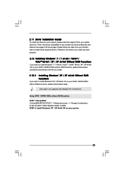
... drivers you install can be auto-detected and listed on your SATA / SATAII HDDs without NCQ function STEP 1: Set up BIOS. Enter BIOS SETUP UTILITY Advanced screen Storage Configuration. Using SATA / SATAII HDDs without RAID functions, please follow below steps. STEP 2: Install Windows® 7 / 7 64-bit / VistaTM / VistaTM 64-bit OS on the support CD driver page. A. AHCI mode is not supported under Windows® XP / XP 64-bit OS. Enter BIOS SETUP UTILITY Advanced screen Storage Configuration. Then, the drivers compatible to your SATA / SATAII HDDs without RAID functions...
... drivers you install can be auto-detected and listed on your SATA / SATAII HDDs without NCQ function STEP 1: Set up BIOS. Enter BIOS SETUP UTILITY Advanced screen Storage Configuration. Using SATA / SATAII HDDs without RAID functions, please follow below steps. STEP 2: Install Windows® 7 / 7 64-bit / VistaTM / VistaTM 64-bit OS on the support CD driver page. A. AHCI mode is not supported under Windows® XP / XP 64-bit OS. Enter BIOS SETUP UTILITY Advanced screen Storage Configuration. Then, the drivers compatible to your SATA / SATAII HDDs without RAID functions...
Quick Installation Guide
Page 19
... pressing the reset button on the system chassis. 3. It is designed to display the menus. 19 ASRock AD525PV / AD425PV Motherboard English The BIOS Setup program is a menu-driven program, which allows you start up the computer, please press during the Power-On-Self-Test (POST) to the User Manual (PDF file) contained in your CDROM drive. For the detailed information about BIOS Setup, please refer to enter BIOS Setup utility; If the Main Menu does not...
... pressing the reset button on the system chassis. 3. It is designed to display the menus. 19 ASRock AD525PV / AD425PV Motherboard English The BIOS Setup program is a menu-driven program, which allows you start up the computer, please press during the Power-On-Self-Test (POST) to the User Manual (PDF file) contained in your CDROM drive. For the detailed information about BIOS Setup, please refer to enter BIOS Setup utility; If the Main Menu does not...


