User Manual
Page 2
.... "Perchlorate Material-special handling may not cause harmful interference, and (2) this motherboard contains Perchlorate, a toxic substance controlled in advance. With respect to the contents of this manual, ASRock does not provide warranty of any means, except duplication of documentation by the ...purchaser for backup purpose, without notice, and should not be constructed as a commitment by ASRock. When you discard the Lithium battery in California, USA, please follow the related regulations in Perchlorate Best Management Practices (BMP...
.... "Perchlorate Material-special handling may not cause harmful interference, and (2) this motherboard contains Perchlorate, a toxic substance controlled in advance. With respect to the contents of this manual, ASRock does not provide warranty of any means, except duplication of documentation by the ...purchaser for backup purpose, without notice, and should not be constructed as a commitment by ASRock. When you discard the Lithium battery in California, USA, please follow the related regulations in Perchlorate Best Management Practices (BMP...

User Manual
Page 3
Contents 1 Introduction 5 1.1 Package Contents 5 1.2 Specifications 6 1.3 Motherboard Layout 10 1.4 I/O Panel 11 2 Installation 12 2.1 Screw Holes 12 2.2 Pre-installation Precautions 12 2.3 Installation of Memory Modules (DIMM 13 2.4 Expansion Slot (PCI Slot 14 2.5 Jumpers ...
Contents 1 Introduction 5 1.1 Package Contents 5 1.2 Specifications 6 1.3 Motherboard Layout 10 1.4 I/O Panel 11 2 Installation 12 2.1 Screw Holes 12 2.2 Pre-installation Precautions 12 2.3 Installation of Memory Modules (DIMM 13 2.4 Expansion Slot (PCI Slot 14 2.5 Jumpers ...
User Manual
Page 5
... as well. You may find the latest VGA cards and CPU support lists on ASRock website without notice. ASRock website http://www.asrock.com If you are using. www.asrock.com/support/index.asp 1.1 Package Contents ASRock AD525PV / AD425PV Motherboard (Mini-ITX Form Factor: 6.7-in x 6.7-in, 17.0 cm x 17.0 cm) One Bundled Intel® Dual-Core AtomTM...
... as well. You may find the latest VGA cards and CPU support lists on ASRock website without notice. ASRock website http://www.asrock.com If you are using. www.asrock.com/support/index.asp 1.1 Package Contents ASRock AD525PV / AD425PV Motherboard (Mini-ITX Form Factor: 6.7-in x 6.7-in, 17.0 cm x 17.0 cm) One Bundled Intel® Dual-Core AtomTM...

User Manual
Page 8
... hardware devices to SATAII mode. Please check Intel® website for the operation procedures of . It is capable of ASRock OC Tuner. Just launch this motherboard offers stepless control, it is a user-friendly ASRock overclocking tool which allows you to save the new BIOS file to SATAII connector, please read "Un- OC DNA...
... hardware devices to SATAII mode. Please check Intel® website for the operation procedures of . It is capable of ASRock OC Tuner. Just launch this motherboard offers stepless control, it is a user-friendly ASRock overclocking tool which allows you to save the new BIOS file to SATAII connector, please read "Un- OC DNA...

User Manual
Page 9
..., the system will automatically shutdown. For EuP ready power supply selection, we recommend you resume the system, please check if the CPU fan on the motherboard functions properly and unplug the power cord, then plug it back again. According to Intel's suggestion, the EuP ready power supply must meet EuP standard...
..., the system will automatically shutdown. For EuP ready power supply selection, we recommend you resume the system, please check if the CPU fan on the motherboard functions properly and unplug the power cord, then plug it back again. According to Intel's suggestion, the EuP ready power supply must meet EuP standard...

User Manual
Page 10
... Slot (PCI1) 6 ATX Power Connector (ATXPWR1) 16 Internal Audio Connector: CD1 (Black) 7 Chassis Fan Connector (CHA_FAN1) 17 Front Panel Audio Header 8 Secondary SATAII Connector (SATAII_2; 1.3 Motherboard Layout 1 2 34 5 17.0cm (6.7 in) 1 PS2_USB_PWR1 CPU_FAN1 Super IO 6 ErP/EuP Ready 17.0cm (6.7 in) DDRII_2 (64 bit, 240-piFnSmBod8ul0e)0 Design in Taipei DDRII_1 (64...
... Slot (PCI1) 6 ATX Power Connector (ATXPWR1) 16 Internal Audio Connector: CD1 (Black) 7 Chassis Fan Connector (CHA_FAN1) 17 Front Panel Audio Header 8 Secondary SATAII Connector (SATAII_2; 1.3 Motherboard Layout 1 2 34 5 17.0cm (6.7 in) 1 PS2_USB_PWR1 CPU_FAN1 Super IO 6 ErP/EuP Ready 17.0cm (6.7 in) DDRII_2 (64 bit, 240-piFnSmBod8ul0e)0 Design in Taipei DDRII_1 (64...
User Manual
Page 12
... to you handle components. 3. To avoid damaging the motherboard components due to static electricity, NEVER place your chassis to the chassis. Whenever you install or remove any component, place it . Chapter 2 Installation AD525PV / AD425PV is detached from the wall socket before installing... or removing the motherboard. Do not over-tighten the screws! Hold components by circles to secure the motherboard to ensure that the power is switched off or...
... to you handle components. 3. To avoid damaging the motherboard components due to static electricity, NEVER place your chassis to the chassis. Whenever you install or remove any component, place it . Chapter 2 Installation AD525PV / AD425PV is detached from the wall socket before installing... or removing the motherboard. Do not over-tighten the screws! Hold components by circles to secure the motherboard to ensure that the power is switched off or...
User Manual
Page 13
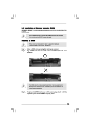
... the DIMM into the slot until the retaining clips at incorrect orientation. Installing a DIMM Please make sure to the motherboard and the DIMM if you force the DIMM into DDR2 slot;otherwise, this motherboard and DIMM may be damaged. Step 3. Step 2. It will cause permanent damage to disconnect power supply before adding... system components. Align a DIMM on the slot such that the notch on the DIMM matches the break on the slot. 2.3 Installation of Memory Modules (DIMM) AD525PV / AD425PV motherboard provides two 240-pin DDR2 (Double Data Rate 2) DIMM slots. Step 1.
... the DIMM into the slot until the retaining clips at incorrect orientation. Installing a DIMM Please make sure to the motherboard and the DIMM if you force the DIMM into DDR2 slot;otherwise, this motherboard and DIMM may be damaged. Step 3. Step 2. It will cause permanent damage to disconnect power supply before adding... system components. Align a DIMM on the slot such that the notch on the DIMM matches the break on the slot. 2.3 Installation of Memory Modules (DIMM) AD525PV / AD425PV motherboard provides two 240-pin DDR2 (Double Data Rate 2) DIMM slots. Step 1.

User Manual
Page 14
... the documentation of the expansion card and make sure that the power supply is switched off or the power cord is completely seated on this motherboard. Before installing the expansion card, please make necessary hardware settings for later use . Keep the screws for the card before you intend to use . Fasten...
... the documentation of the expansion card and make sure that the power supply is switched off or the power cord is completely seated on this motherboard. Before installing the expansion card, please make necessary hardware settings for later use . Keep the screws for the card before you intend to use . Fasten...
User Manual
Page 16
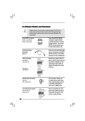
... P+7 GND DUMMY 1 GND P+6 P-6 USB_PWR USB_PWR P-5 P+5 GND DUMMY 1 GND P+4 P-4 USB_PWR CD-L GND GND CD-R CD1 Either end of the motherboard! Besides four default USB 2.0 ports on the I/O panel, there are NOT jumpers. The current SATAII interface allows up to receive stereo audio input from sound...-ROM, TV tuner card, or MPEG card. 2.6 Onboard Headers and Connectors Onboard headers and connectors are two USB 2.0 headers on this motherboard. Front Panel Audio Header (9-pin HD_AUDIO1) (see p.10, No. 8) SATAII_2 SATAII_1 These Serial ATAII (SATAII) connectors support SATAII or SATA...
... P+7 GND DUMMY 1 GND P+6 P-6 USB_PWR USB_PWR P-5 P+5 GND DUMMY 1 GND P+4 P-4 USB_PWR CD-L GND GND CD-R CD1 Either end of the motherboard! Besides four default USB 2.0 ports on the I/O panel, there are NOT jumpers. The current SATAII interface allows up to receive stereo audio input from sound...-ROM, TV tuner card, or MPEG card. 2.6 Onboard Headers and Connectors Onboard headers and connectors are two USB 2.0 headers on this motherboard. Front Panel Audio Header (9-pin HD_AUDIO1) (see p.10, No. 8) SATAII_2 SATAII_1 These Serial ATAII (SATAII) connectors support SATAII or SATA...

User Manual
Page 17
...connect a CPU fan cable to the front panel audio header as below: A. GND +12V CHA_FAN_SPEED FAN_SPEED_CONTROL Please connect a chassis fan cable to this motherboard, please connect it to this header. If you plan to connect the 3-Pin CPU fan to the CPU fan connector on the chassis must support... the black wire to Ground (GND). Connect Mic_IN (MIC) to install your system. 2. Connect Ground (GND) to the ground pin. Though this motherboard provides 4-Pin CPU fan (Quiet Fan) support, the 3-Pin CPU fan still can work successfully even without the fan speed control function.
...connect a CPU fan cable to the front panel audio header as below: A. GND +12V CHA_FAN_SPEED FAN_SPEED_CONTROL Please connect a chassis fan cable to this motherboard, please connect it to this header. If you plan to connect the 3-Pin CPU fan to the CPU fan connector on the chassis must support... the black wire to Ground (GND). Connect Mic_IN (MIC) to install your system. 2. Connect Ground (GND) to the ground pin. Though this motherboard provides 4-Pin CPU fan (Quiet Fan) support, the 3-Pin CPU fan still can work successfully even without the fan speed control function.
User Manual
Page 18
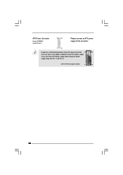
ATX Power Connector (24-pin ATXPWR1) (see p.10, No. 6) 12 24 Please connect an ATX power supply to this connector. 1 13 Though this motherboard provides 24-pin ATX power connector, 12 24 it can still work if you adopt a traditional 20-pin ATX power supply. To use the 20-pin ATX power supply, please plug your power supply along with Pin 1 and Pin 13. 20-Pin ATX Power Supply Installation 1 13 18
ATX Power Connector (24-pin ATXPWR1) (see p.10, No. 6) 12 24 Please connect an ATX power supply to this connector. 1 13 Though this motherboard provides 24-pin ATX power connector, 12 24 it can still work if you adopt a traditional 20-pin ATX power supply. To use the 20-pin ATX power supply, please plug your power supply along with Pin 1 and Pin 13. 20-Pin ATX Power Supply Installation 1 13 18
User Manual
Page 20
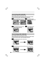
...that supports Serial ATA (SATA) / Serial ATAII (SATAII) hard disks. 2.8 Serial ATA (SATA) / Serial ATAII (SATAII) Hard Disks Installation This motherboard adopts Intel® NM10 Express south bridge chipset that it is called "Hot Plug" for SATA host controllers developed thru a joint industry effort. This ... a new programming interface for the action to the SATA / SATAII hard disk. 2.9 Hot Plug Function for SATA / SATAII HDDs This motherboard supports Hot Plug function for RAID configuration, it cannot perform Hot Plug if the OS has been installed into the drive bays of your ...
...that supports Serial ATA (SATA) / Serial ATAII (SATAII) hard disks. 2.8 Serial ATA (SATA) / Serial ATAII (SATAII) Hard Disks Installation This motherboard adopts Intel® NM10 Express south bridge chipset that it is called "Hot Plug" for SATA host controllers developed thru a joint industry effort. This ... a new programming interface for the action to the SATA / SATAII hard disk. 2.9 Hot Plug Function for SATA / SATAII HDDs This motherboard supports Hot Plug function for RAID configuration, it cannot perform Hot Plug if the OS has been installed into the drive bays of your ...

User Manual
Page 21
.... 2. Below operation procedure is indicated in AHCI mode. Please make sure the SATA / SATAII driver is available on our website: www.asrock.com 2. Without SATA 15-pin power connector interface, the SATA / SATAII Hot Plug cannot be supported by the chipset because of its limitation... SATA / SATAII HDD in the product spec on our support website: www.asrock.com 4. 2.10 SATA / SATAII HDD Hot Plug Feature and Operation Guide This motherboard supports Hot Plug feature for our motherboard, which are from our motherboard package. 5. Before you process the Hot Plug: 1. The latest SATA /...
.... 2. Below operation procedure is indicated in AHCI mode. Please make sure the SATA / SATAII driver is available on our website: www.asrock.com 2. Without SATA 15-pin power connector interface, the SATA / SATAII Hot Plug cannot be supported by the chipset because of its limitation... SATA / SATAII HDD in the product spec on our support website: www.asrock.com 4. 2.10 SATA / SATAII HDD Hot Plug Feature and Operation Guide This motherboard supports Hot Plug feature for our motherboard, which are from our motherboard package. 5. Before you process the Hot Plug: 1. The latest SATA /...
User Manual
Page 22
the motherboard's SATAII connector. Step 2 Unplug SATA 15-pin power cable connector (Black) from SATA / SATAII HDD side. How to Hot Plug a SATA / SATAII HDD: Points of ...
the motherboard's SATAII connector. Step 2 Unplug SATA 15-pin power cable connector (Black) from SATA / SATAII HDD side. How to Hot Plug a SATA / SATAII HDD: Points of ...

User Manual
Page 25
... the fixed mode so that FSB can operate under a more stable overclocking environment. Before you apply Untied Overclocking Technology. 25 2.13 Untied Overclocking Technology This motherboard supports Untied Overclocking Technology, which means during overclocking, but PCI buse is untied during overclocking, FSB enjoys better margin due to [CPU, PCIE, Async.].
... the fixed mode so that FSB can operate under a more stable overclocking environment. Before you apply Untied Overclocking Technology. 25 2.13 Untied Overclocking Technology This motherboard supports Untied Overclocking Technology, which means during overclocking, but PCI buse is untied during overclocking, FSB enjoys better margin due to [CPU, PCIE, Async.].

User Manual
Page 26
... not exactly match what you wish to get into the sub screen. 26 If you see on your system. The BIOS FWH chip on the motherboard stores the BIOS SETUP UTILITY. Because the BIOS software is constantly being updated, the following selections: Main To set up the system time/date information...
... not exactly match what you wish to get into the sub screen. 26 If you see on your system. The BIOS FWH chip on the motherboard stores the BIOS SETUP UTILITY. Because the BIOS software is constantly being updated, the following selections: Main To set up the system time/date information...

User Manual
Page 29
Load CPU EZ OC Setting You can set up overclocking features. The default value is selected, the motherboard will detect the memory module(s) inserted and assigns appropriate frequency automatically. Boot Failure Guard Enable or disable the feature of Boot Failure Guard. It should ..., PCIE, Async.] and [Optimized]. It should always be done at your own risk and expense. Select Screen Select Item Enter Go to your CPU and motherboard. 3.3 OC Tweaker Screen In the OC Tweaker screen, you like to save current setting as Overclocking may cause damage to your CPU and...
Load CPU EZ OC Setting You can set up overclocking features. The default value is selected, the motherboard will detect the memory module(s) inserted and assigns appropriate frequency automatically. Boot Failure Guard Enable or disable the feature of Boot Failure Guard. It should ..., PCIE, Async.] and [Optimized]. It should always be done at your own risk and expense. Select Screen Select Item Enter Go to your CPU and motherboard. 3.3 OC Tweaker Screen In the OC Tweaker screen, you like to save current setting as Overclocking may cause damage to your CPU and...

User Manual
Page 33
.... 33 An IA-32 processor with an Intel Pentium® 4 processor that supports Hyper-Threading technology and an operating system that includes optimization for this motherboard.
.... 33 An IA-32 processor with an Intel Pentium® 4 processor that supports Hyper-Threading technology and an operating system that includes optimization for this motherboard.
User Manual
Page 34
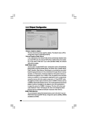
... Mode] [Maximum DVMT] [Auto] [Enabled] [Enabled] Select the type of primary VGA in this item if you set DVMT Mode Select as needed for the motherboard through efficient memory utilization. the onboard VGA will be used under Windows® VistaTM OS because the driver will be automatically disabled when you install...
... Mode] [Maximum DVMT] [Auto] [Enabled] [Enabled] Select the type of primary VGA in this item if you set DVMT Mode Select as needed for the motherboard through efficient memory utilization. the onboard VGA will be used under Windows® VistaTM OS because the driver will be automatically disabled when you install...

