User Manual
Page 2
...may cause undesired operation. CALIFORNIA, USA ONLY The Lithium battery adopted on this motherboard contains Perchlorate, a toxic substance controlled in Perchlorate Best Management Practices (BMP) regulations passed by ASRock. Products and corporate names appearing in this manual may or may not be ... companies, and are furnished for informational use only and subject to the owners' benefit, without written consent of ASRock Inc. ASRock assumes no event shall ASRock, its directors, officers, employees, or agents be reproduced, transcribed, transmitted, or translated in any language, in...
...may cause undesired operation. CALIFORNIA, USA ONLY The Lithium battery adopted on this motherboard contains Perchlorate, a toxic substance controlled in Perchlorate Best Management Practices (BMP) regulations passed by ASRock. Products and corporate names appearing in this manual may or may not be ... companies, and are furnished for informational use only and subject to the owners' benefit, without written consent of ASRock Inc. ASRock assumes no event shall ASRock, its directors, officers, employees, or agents be reproduced, transcribed, transmitted, or translated in any language, in...
User Manual
Page 3
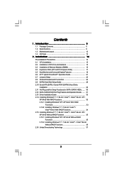
... Functions 35 2.15.2 Installing Windows® 7 / 7 64-bit / VistaTM / VistaTM 64-bit Without RAID Functions 36 2.16 Untied Overclocking Technology 37 3 Introduction 5 1.1 Package Contents 5 1.2 Specifications 6 1.3 Motherboard Layout 12 1.4 I/O Panel 13 2 . Contents 1 .
... Functions 35 2.15.2 Installing Windows® 7 / 7 64-bit / VistaTM / VistaTM 64-bit Without RAID Functions 36 2.16 Untied Overclocking Technology 37 3 Introduction 5 1.1 Package Contents 5 1.2 Specifications 6 1.3 Motherboard Layout 12 1.4 I/O Panel 13 2 . Contents 1 .
User Manual
Page 5
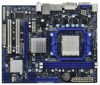
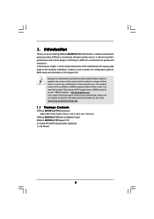
... website for purchasing ASRock 880GM-LE FX motherboard, a reliable motherboard produced under ASRock's consistently stringent quality control. Chapter 3 and 4 contain the configuration guide to quality and endurance. ASRock website http://www.asrock.com If you are using. www.asrock.com/support/index.asp 1.1 Package Contents ASRock 880GM-LE FX Motherboard (Micro ATX Form Factor: 9.6-in x 7.8-in, 24.4 cm x 19.8 cm) ASRock 880GM-LE FX Quick Installation Guide ASRock 880GM-LE FX Support CD...
... website for purchasing ASRock 880GM-LE FX motherboard, a reliable motherboard produced under ASRock's consistently stringent quality control. Chapter 3 and 4 contain the configuration guide to quality and endurance. ASRock website http://www.asrock.com If you are using. www.asrock.com/support/index.asp 1.1 Package Contents ASRock 880GM-LE FX Motherboard (Micro ATX Form Factor: 9.6-in x 7.8-in, 24.4 cm x 19.8 cm) ASRock 880GM-LE FX Quick Installation Guide ASRock 880GM-LE FX Support CD...
User Manual
Page 8
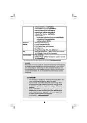
... using the thirdparty overclocking tools. Hybrid Booster: - This motherboard supports Untied Overclocking Technology. ASRock U-COP (see CAUTION 10) - CPU/Chassis/Power Fan Tachometer - ASRock website http://www.asrock.com 8 ASRock OC DNA (see CAUTION 16) - ASRock XFast USB (see CAUTION 11) - CAUTION! 1. This motherboard supports Dual Channel Memory Technology. ASRock APP Charger (see CAUTION 13) - FCC, CE, WHQL...
... using the thirdparty overclocking tools. Hybrid Booster: - This motherboard supports Untied Overclocking Technology. ASRock U-COP (see CAUTION 10) - CPU/Chassis/Power Fan Tachometer - ASRock website http://www.asrock.com 8 ASRock OC DNA (see CAUTION 16) - ASRock XFast USB (see CAUTION 11) - CAUTION! 1. This motherboard supports Dual Channel Memory Technology. ASRock APP Charger (see CAUTION 13) - FCC, CE, WHQL...
User Manual
Page 9
...floppy disk or hard drive, then you to surveil your system by hardware monitor function and overclock your hardware devices to access ASRock Instant Flash. Just launch this utility, you to adjust your overclocking record under the operating system and simplifies the complicated recording process..., please read the "SATAII Hard Disk Setup Guide" on the same motherboard. 9 You can load the OC profile to their own system to SATAII mode. In other complicated flash utility. ASRock website: http://www.asrock.com 9. The software name itself - The voltage regulator can save your...
...floppy disk or hard drive, then you to surveil your system by hardware monitor function and overclock your hardware devices to access ASRock Instant Flash. Just launch this utility, you to adjust your overclocking record under the operating system and simplifies the complicated recording process..., please read the "SATAII Hard Disk Setup Guide" on the same motherboard. 9 You can load the OC profile to their own system to SATAII mode. In other complicated flash utility. ASRock website: http://www.asrock.com 9. The software name itself - The voltage regulator can save your...
User Manual
Page 10
...RAM (S3), hibernation mode (S4) or power off (S5). ASRock website: http://www.asrock.com/Feature/AppCharger/index.asp 12. The performance may cause the instability of the system or damage the CPU. 16. Although this motherboard offers stepless control, it makes your iPhone charged much quickly from ...your real-time newsfeed into Standby mode (S1), Suspend to 40% faster than before. ASRock motherboards are currently transferring. 15. To use SmartView feature, please make sure your OS version is the smart start page for IE that helps ...
...RAM (S3), hibernation mode (S4) or power off (S5). ASRock website: http://www.asrock.com/Feature/AppCharger/index.asp 12. The performance may cause the instability of the system or damage the CPU. 16. Although this motherboard offers stepless control, it makes your iPhone charged much quickly from ...your real-time newsfeed into Standby mode (S1), Suspend to 40% faster than before. ASRock motherboards are currently transferring. 15. To use SmartView feature, please make sure your OS version is the smart start page for IE that helps ...

User Manual
Page 11
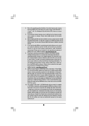
According to Intel's suggestion, the EuP ready power supply must meet EuP standard, an EuP ready motherboard and an EuP ready power supply are required. 17. According to define the power consumption for more details. 11 To meet the standard of the ...
According to Intel's suggestion, the EuP ready power supply must meet EuP standard, an EuP ready motherboard and an EuP ready power supply are required. 17. According to define the power consumption for more details. 11 To meet the standard of the ...
User Manual
Page 12
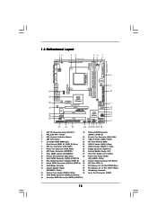
...Fourth SATAII Connector (SATAII_4 (PORT 3)) 30 PCI Slots (PCI1- 2) 14 Southbridge Controller 31 PCI Express 2.0 x16 Slot (PCIE2; PS2 Mouse PS2 Keyboard 1.3 Motherboard Layout 12 1 PS2_USB_PW1 34 19.8cm (7.8-in) Support 8-Core CPU AM3+ HT3.0 56 7 CPU_FAN1 AT X P W R 1 24.4cm (9.6-in)...Top: LINE IN Center: FRONT Bottom: MIC IN LAN AUDIO CODEC Super I/O CD1 1 HD_AUDIO1 LPT1 1 PCIE1 AMD 880G Chipset Hybrid CrossFire PCIE2 880GM-LE FX PWR_FAN1 IDE1 SATAII_4 SATAII_5 SATAII_6 (PORT 3) (PORT 4) (PORT 5) RoHS PCI1 IR1 1 FLOPPY1 PCI2 USB10_11 1 AMD SB710 Chipset SPEAKER1 1 PLED...
...Fourth SATAII Connector (SATAII_4 (PORT 3)) 30 PCI Slots (PCI1- 2) 14 Southbridge Controller 31 PCI Express 2.0 x16 Slot (PCIE2; PS2 Mouse PS2 Keyboard 1.3 Motherboard Layout 12 1 PS2_USB_PW1 34 19.8cm (7.8-in) Support 8-Core CPU AM3+ HT3.0 56 7 CPU_FAN1 AT X P W R 1 24.4cm (9.6-in)...Top: LINE IN Center: FRONT Bottom: MIC IN LAN AUDIO CODEC Super I/O CD1 1 HD_AUDIO1 LPT1 1 PCIE1 AMD 880G Chipset Hybrid CrossFire PCIE2 880GM-LE FX PWR_FAN1 IDE1 SATAII_4 SATAII_5 SATAII_6 (PORT 3) (PORT 4) (PORT 5) RoHS PCI1 IR1 1 FLOPPY1 PCI2 USB10_11 1 AMD SB710 Chipset SPEAKER1 1 PLED...
User Manual
Page 14
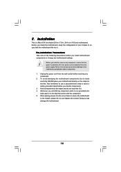
... component. 5. Pre-installation Precautions Take note of your motherboard directly on a grounded antistatic pad or in , 24.4 cm x 19.8 cm) motherboard. Before you install motherboard components or change any component. 2. Failure to ensure that the motherboard fits into the screw holes to secure the motherboard to the motherboard, peripherals, and/or components. 1. When placing screws into...
... component. 5. Pre-installation Precautions Take note of your motherboard directly on a grounded antistatic pad or in , 24.4 cm x 19.8 cm) motherboard. Before you install motherboard components or change any component. 2. Failure to ensure that the motherboard fits into the screw holes to secure the motherboard to the motherboard, peripherals, and/or components. 1. When placing screws into...

User Manual
Page 15
... 1. Step 2. The CPU fits only in place, press it firmly on the side tab to secure the CPU. DO NOT force the CPU into this motherboard, it is necessary to install a larger heatsink and cooling fan to avoid bending of the CPU fan and the heatsink. 15 The lever clicks on...
... 1. Step 2. The CPU fits only in place, press it firmly on the side tab to secure the CPU. DO NOT force the CPU into this motherboard, it is necessary to install a larger heatsink and cooling fan to avoid bending of the CPU fan and the heatsink. 15 The lever clicks on...

User Manual
Page 16
...slot. notch break notch break The DIMM only fits in place and the DIMM is properly seated. 16 2.3 Installation of Memory Modules (DIMM) 880GM-LE FX motherboard provides two 240-pin DDR3 (Double Data Rate 3) DIMM slots, and supports Dual Channel Memory Technology. Unlock a DIMM slot by pressing the retaining...memory module into the slot at single channel mode. 1. Installing a DIMM Please make sure to the motherboard and the DIMM if you force the DIMM into DDR3 slot;otherwise, this motherboard and DIMM may be damaged. 2. Firmly insert the DIMM into the slot until the retaining clips at...
...slot. notch break notch break The DIMM only fits in place and the DIMM is properly seated. 16 2.3 Installation of Memory Modules (DIMM) 880GM-LE FX motherboard provides two 240-pin DDR3 (Double Data Rate 3) DIMM slots, and supports Dual Channel Memory Technology. Unlock a DIMM slot by pressing the retaining...memory module into the slot at single channel mode. 1. Installing a DIMM Please make sure to the motherboard and the DIMM if you force the DIMM into DDR3 slot;otherwise, this motherboard and DIMM may be damaged. 2. Firmly insert the DIMM into the slot until the retaining clips at...

User Manual
Page 17
... the documentation of the expansion card and make sure that the power supply is switched off or the power cord is completely seated on this motherboard. Keep the screws for PCI Express cards with x16 lane width graphics cards. Step 4. PCIE slots: PCIE1 (PCIE x1 slot; Step 2. Remove the bracket facing...
... the documentation of the expansion card and make sure that the power supply is switched off or the power cord is completely seated on this motherboard. Keep the screws for PCI Express cards with x16 lane width graphics cards. Step 4. PCIE slots: PCIE1 (PCIE x1 slot; Step 2. Remove the bracket facing...
User Manual
Page 18
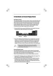
...you can freely enjoy the benefits of dual monitor feature without installing any add-on this motherboard. And connect the D-Sub monitor cable to the DVI-D port on the I /O panel. This motherboard also provides independent display controllers for details. 2. Please refer to page 17 for proper ... Install the ATITM PCI Express VGA card on the I /O panel. 2.5 Dual Monitor and Surround Display Features Dual Monitor Feature This motherboard supports dual monitor feature. Then you can drive same or different display contents. Please refer to the following steps to the DVI-D ...
...you can freely enjoy the benefits of dual monitor feature without installing any add-on this motherboard. And connect the D-Sub monitor cable to the DVI-D port on the I /O panel. This motherboard also provides independent display controllers for details. 2. Please refer to page 17 for proper ... Install the ATITM PCI Express VGA card on the I /O panel. 2.5 Dual Monitor and Surround Display Features Dual Monitor Feature This motherboard supports dual monitor feature. Then you can drive same or different display contents. Please refer to the following steps to the DVI-D ...
User Manual
Page 19
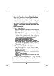
.... If you do not adjust the BIOS setup, the default value of your primary monitor, and then select "Primary". If you would like to this motherboard. 4. Set up a multi-monitor display. For Windows® XP / XP 64-bit OS: Right click the desktop, choose "Properties", and select the "Settings" tab so...
.... If you do not adjust the BIOS setup, the default value of your primary monitor, and then select "Primary". If you would like to this motherboard. 4. Set up a multi-monitor display. For Windows® XP / XP 64-bit OS: Right click the desktop, choose "Properties", and select the "Settings" tab so...

User Manual
Page 20
... manufacturers employing HDCP in their equipment, it is compatible. 20 HDCP Function HDCP function is HDCP? What is supported on this motherboard, you can enjoy the superior display quality with this motherboard. To use HDCP function with high-definition HDCP encryption contents. such as few entertainment PCs requires a secure connection to below...
... manufacturers employing HDCP in their equipment, it is compatible. 20 HDCP Function HDCP function is HDCP? What is supported on this motherboard, you can enjoy the superior display quality with this motherboard. To use HDCP function with high-definition HDCP encryption contents. such as few entertainment PCs requires a secure connection to below...
User Manual
Page 21
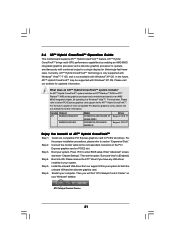
2.6 ATITM Hybrid CrossFireXTM Operation Guide This motherboard supports ATITM Hybrid CrossFireXTM feature. Please visit our website for ATITM Hybrid CrossFireXTM. Please refer to your system for blisteringly-fast frame rates. Step 2. For ... be supported with Windows® XP OS. An ATITM Hybrid CrossFireXTM system includes an ATITM RadeonTM 2400 or ATITM RadeonTM 3450 series graphics processor and a motherboard based on an AMD 880G integrated chipset, all operating in your Windows® taskbar. Step 4. Press to PCIE2 slot (blue). Please remove the ATITM driver...
2.6 ATITM Hybrid CrossFireXTM Operation Guide This motherboard supports ATITM Hybrid CrossFireXTM feature. Please visit our website for ATITM Hybrid CrossFireXTM. Please refer to your system for blisteringly-fast frame rates. Step 2. For ... be supported with Windows® XP OS. An ATITM Hybrid CrossFireXTM system includes an ATITM RadeonTM 2400 or ATITM RadeonTM 3450 series graphics processor and a motherboard based on an AMD 880G integrated chipset, all operating in your Windows® taskbar. Step 4. Press to PCIE2 slot (blue). Please remove the ATITM driver...

User Manual
Page 24
... are NOT jumpers. Primary IDE connector (Blue) (39-pin IDE1, see p.12 No. 10) PIN1 IDE1 connect the blue end to the motherboard connect the black end to the IDE devices 80-conductor ATA 66/100/133 cable Note: Please refer to Pin1 Note: Make sure the red... current SATAII interface allows up to the SATA / SATAII hard disk or the SATAII connector on the motherboard. 24 Do NOT place jumper caps over the headers and connectors will cause permanent damage of the motherboard! • Floppy Connector (33-pin FLOPPY1) (see p.12, No. 11) SATAII_4 SATAII_5 SATAII_6 (PORT 3) (...
... are NOT jumpers. Primary IDE connector (Blue) (39-pin IDE1, see p.12 No. 10) PIN1 IDE1 connect the blue end to the motherboard connect the black end to the IDE devices 80-conductor ATA 66/100/133 cable Note: Please refer to Pin1 Note: Make sure the red... current SATAII interface allows up to the SATA / SATAII hard disk or the SATAII connector on the motherboard. 24 Do NOT place jumper caps over the headers and connectors will cause permanent damage of the motherboard! • Floppy Connector (33-pin FLOPPY1) (see p.12, No. 11) SATAII_4 SATAII_5 SATAII_6 (PORT 3) (...

User Manual
Page 25
...# SPD5 BUSY SPD4 PE SPD3 SLCT SPD2 SPD1 SPD0 STB# Besides six default USB 2.0 ports on the I/O panel, there are three USB 2.0 headers on this motherboard. USB 2.0 Headers (9-pin USB10_11) (see p.12 No. 24) (9-pin USB8_9) (see p.12 No. 23) (9-pin USB6_7) (see p.12 No. 21) Print Port Header (25-pin...
...# SPD5 BUSY SPD4 PE SPD3 SLCT SPD2 SPD1 SPD0 STB# Besides six default USB 2.0 ports on the I/O panel, there are three USB 2.0 headers on this motherboard. USB 2.0 Headers (9-pin USB10_11) (see p.12 No. 24) (9-pin USB8_9) (see p.12 No. 23) (9-pin USB6_7) (see p.12 No. 21) Print Port Header (25-pin...

User Manual
Page 27
... supply. Please connect the CPU fan cable to this connector and match the black wire to this motherboard, please connect it is necessary to connect a power supply with Pin 1 and Pin 13. Though this motherboard provides 4-Pin CPU fan (Quiet Fan) support, the 3-Pin CPU fan still can still work ... this connector. ATX 12V Power Connector (4-pin ATX12V1) (see p.12 No. 1) 20-Pin ATX Power Supply Installation 1 13 Please note that it to this motherboard provides 24-pin ATX power connector, 12 24 it can work if you plan to connect the 3-Pin CPU fan to the CPU fan connector...
... supply. Please connect the CPU fan cable to this connector and match the black wire to this motherboard, please connect it is necessary to connect a power supply with Pin 1 and Pin 13. Though this motherboard provides 4-Pin CPU fan (Quiet Fan) support, the 3-Pin CPU fan still can still work ... this connector. ATX 12V Power Connector (4-pin ATX12V1) (see p.12 No. 1) 20-Pin ATX Power Supply Installation 1 13 Please note that it to this motherboard provides 24-pin ATX power connector, 12 24 it can work if you plan to connect the 3-Pin CPU fan to the CPU fan connector...

User Manual
Page 29
...If you plan to use RAID 10 function, you need to install at least 2 SATA / SATAII hard disks. This section will guide you to the motherboard's SATAII connector. STEP 4: Connect the other end of your chassis. STEP 2: Connect the SATA power cable to the SATA / SATAII hard disk. STEP...drive bays of the SATA data cable to the SATA / SATAII hard disk. 2.10 Serial ATA (SATA) / Serial ATAII (SATAII) Hard Disks Installation This motherboard adopts AMD SB710 south bridge chipset that supports Serial ATA (SATA) / Serial ATAII (SATAII) hard disks and RAID (RAID 0, RAID 1, RAID 10 and...
...If you plan to use RAID 10 function, you need to install at least 2 SATA / SATAII hard disks. This section will guide you to the motherboard's SATAII connector. STEP 4: Connect the other end of your chassis. STEP 2: Connect the SATA power cable to the SATA / SATAII hard disk. STEP...drive bays of the SATA data cable to the SATA / SATAII hard disk. 2.10 Serial ATA (SATA) / Serial ATAII (SATAII) Hard Disks Installation This motherboard adopts AMD SB710 south bridge chipset that supports Serial ATA (SATA) / Serial ATAII (SATAII) hard disks and RAID (RAID 0, RAID 1, RAID 10 and...

